Page 867 of 1771

Troubleshooting
Troubleshooting Procedures (cont'd)
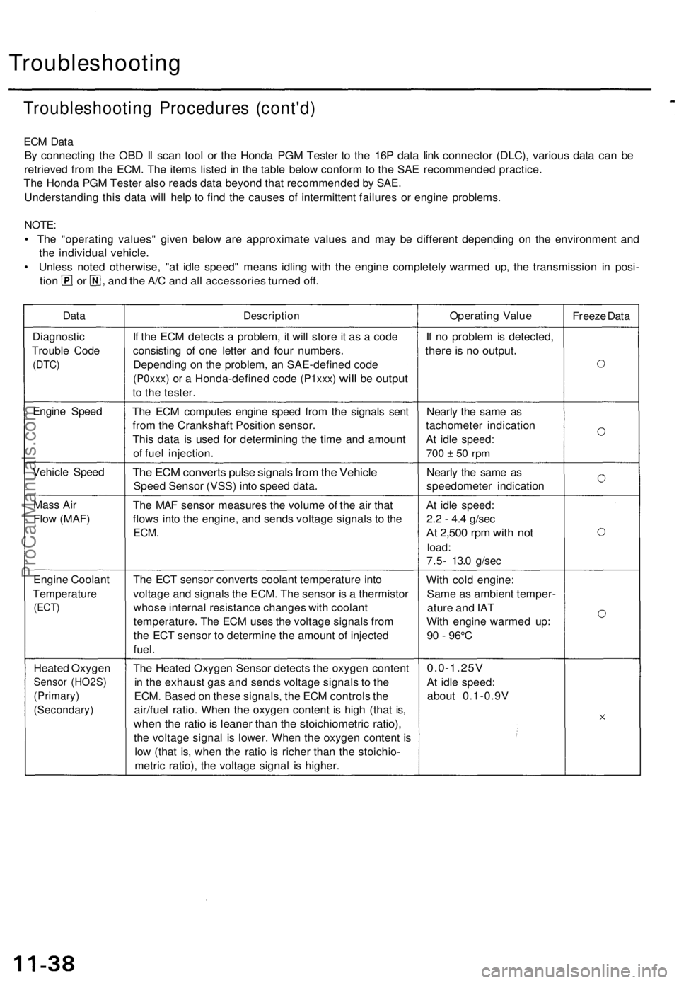
ECM Data
By connecting the OBD II scan tool or the Honda PGM Tester to the 16P data link connector (DLC), various data can be
retrieved from the ECM. The items listed in the table below conform to the SAE recommended practice.
The Honda PGM Tester also reads data beyond that recommended by SAE.
Understanding this data will help to find the causes of intermittent failures or engine problems.
NOTE:
• The "operating values" given below are approximate values and may be different depending on the environment and
the individual vehicle.
• Unless noted otherwise, "at idle speed" means idling with the engine completely warmed up, the transmission in posi-
tion or , and the A/C and all accessories turned off.
Data
Description
Operating Value
Freeze Data
Diagnostic
Trouble Code
(DTC)
If the ECM detects a problem, it will store it as a code
consisting of one letter and four numbers.
Depending on the problem, an SAE-defined code
(P0xxx)
or a
Honda-defined code
(P1xxx)
will
be
output
to the tester.
If no problem is detected,
there is no output.
Engine Speed
The ECM computes engine speed from the signals sent
from the Crankshaft Position sensor.
This data is used for determining the time and amount
of fuel injection.
Nearly the same as
tachometer indication
At idle speed:
700 ± 50 rpm
Vehicle Speed
The ECM converts pulse signals from the Vehicle
Speed Sensor (VSS) into speed data.
Nearly the same as
speedometer indication
Mass Air
Flow (MAF)
The MAF sensor measures the volume of the air that
flows into the engine, and sends voltage signals to the
ECM.
At idle speed:
2.2 - 4.4 g/sec
At 2,500 rpm with not
load:
7.5- 13.0 g/sec
Engine Coolant
Temperature
(ECT)
The ECT sensor converts coolant temperature into
voltage and signals the ECM. The sensor is a thermistor
whose internal resistance changes with coolant
temperature. The ECM uses the voltage signals from
the ECT sensor to determine the amount of injected
fuel.
With cold engine:
Same as ambient temper-
ature and IAT
With engine warmed up:
90 - 96°C
Heated Oxygen
Sensor (HO2S)
(Primary)
(Secondary)
The Heated Oxygen Sensor detects the oxygen content
in the exhaust gas and sends voltage signals to the
ECM. Based on these signals, the ECM controls the
air/fuel ratio. When the oxygen content is high (that is,
when the ratio is leaner than the stoichiometric ratio),
the voltage signal is lower. When the oxygen content is
low (that is, when the ratio is richer than the stoichio-
metric ratio), the voltage signal is higher.
0.0-1.25V
At idle speed:
about 0.1-0.9VProCarManuals.com
Page 1593 of 1771
Gauge/Terminal Locatio n Inde x
CONNECTO R "A " (C612 )
CONNECTOR "B " (C613 )
FUE L GAUGE :
Gaug e Test , pag e 23-12 1
Sendin g Uni t Test , pag e 23-12 2 ENGIN
E COOLAN T TEMPERATUR E (ECT ) GAUGE :
Gaug e Test , pag e 23-12 4
Sendin g Uni t Test , pag e 23-12 4
SPEEDOMETER :Indicates 6 0 mp h a t 102 5 rp m(60 km/ h at 63 7 rpm ) of th evehicl e spee d senso r (VSS) .
CONNECTO R "D " (C615 ) CONNECTO
R "C " (C614 )
SAFET
Y INDICATO R
Se e pag e 23-13 5
TACHOMETER :Indicates 10 0 rp m a t
25 0 pulse s pe r minut e
of th e ignitio n contro lmodule (ICM) .
A/
T GEA R POSITIO N
INDICATO R SYSTE M
Se e pag e 23-14 2
ProCarManuals.com
Page 1597 of 1771
Speedometer/Trip Meter/Odometer
Troubleshooting
NOTE:
The numbers in the table show the troubleshooting sequence.
If necessary, replace the speedometer, trip meter, and odometer as a unit.
VSS Input Test
Trml
Wire
Test condition
Test: Desired result
Possible cause if result is not obtained
1
2
3
BLK
YEL
ORN
Under all conditions
Ignition switch ON (II)
Ignition switch ON (II)
Check for continuity to ground:
There should be continuity.
Check for voltage to ground:
There should be battery voltage.
Check for voltage to ground:
There should be about 5 V or more.
• Poor ground (G101)
• An open in the wire
• Blown No. 1 (10 A) fuse in the
under-dash fuse/relay box
• Short to ground
• An open in the wire
• Short to ground
• An open in the wire
NOTE: A short to ground in the ORN wire can be caused by a short in any component connected to it.ProCarManuals.com
Page 1598 of 1771

Vehicle Spee d Senso r (VSS )
Troubleshootin g
Speedometer, tri p meter , an d odomete r d o no t work .
Befor e testing , inspec t th e No . 1 (1 0 A ) fus e in th e under-das h fuse/rela y box .
TEST HARNES S
07LA J - PT3020 A
RED TES T HARNES S
CLIP
PROTECTIV ETAPE
VSS
Is ther e continuity ?Repair ope n i n th e BL K wir ebetwee n th e VS S an d G101 .GRN TES T HARNES S
CLI P
TES T HARNES S
07LA J - PT3020 A
Tes t th e YE L wire :
1 . Connec t th e othe r tes t harnes s
connecto r t o th e VSS .
2. Connec t th e WH T tes t harnes sclip t o th e positiv e prob e o f avoltmeter , an d connec t th e RE D
tes t harnes s cli p t o th e negativ e
probe.3. Tur n th e ignitio n switc h O N (II) .
RED TES T HARNES S
Is ther e batter y voltage ?Repair ope n i n th e YE L wir ebetwee n th e VS S an d th e under -dash fuse/rela y box .VSS
PROTECTIV ETAPE
WH T TES T HARNES S CLI P
(T o pag e 23-119 )
Tes
t th e BL K wire :
1. Disconnec t th e 3 P connecto rfrom th e vehicl e spee d senso r(VSS).2. Connec t th e tes t harnes s onl yto th e engin e wir e harness .3. Connec t th e RE D tes t harnes sclip to th e positiv e prob e o f a nohmmeter .4. Chec k fo r continuit y betwee nthe RE D tes t harnes s cli p an dbod y ground .
ProCarManuals.com
Page 1599 of 1771

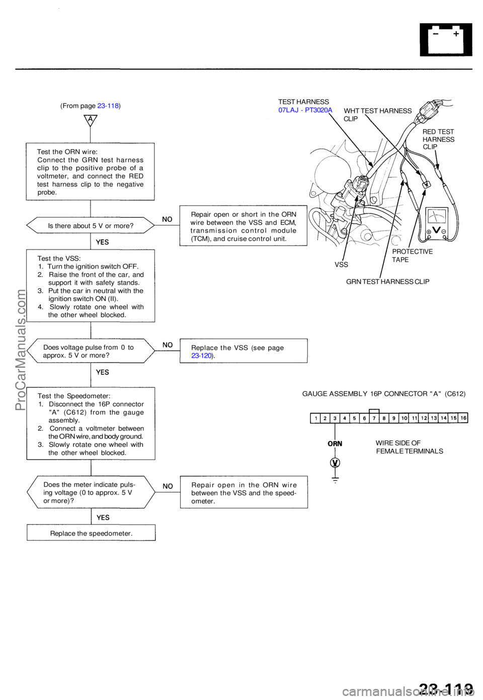
(From pag e 23-118 ) TES
T HARNES S
07LA J - PT3020 A
Tes t th e OR N wire :
Connec t th e GR N tes t harnes s
clip t o th e positiv e prob e o f avoltmeter , an d connec t th e RE D
tes t harnes s cli p t o th e negativ e
probe .
I s ther e abou t 5 V or more ? Repai
r ope n o r shor t i n th e OR N
wir e betwee n th e VS S an d ECM ,
transmissio n contro l modul e
(TCM) , an d cruis e contro l unit .
Tes t th e VSS :
1. Tur n th e ignitio n switc h OFF .2. Rais e th e fron t o f th e car , an d
suppor t i t wit h safet y stands .
3. Pu t th e ca r i n neutra l wit h th eignitio n switc h O N (II) .4. Slowl y rotat e on e whee l wit h
th e othe r whee l blocked .
VSS
GR N TES T HARNES S CLI P
Doe s voltag e puls e fro m 0 to
approx . 5 V or more ? Replac
e th e VS S (se e pag e
23-120 ).
Tes t th e Speedometer :
1 . Disconnec t th e 16 P connecto r
"A " (C612 ) fro m th e gaug e
assembly .
2 . Connec t a voltmete r betwee n
the OR N wire , an d bod y ground .3. Slowl y rotat e on e whee l wit hthe othe r whee l blocked . GAUG
E ASSEMBL Y 16 P CONNECTO R "A " (C612 )
WIR E SID E O F
FEMAL E TERMINAL S
Doe s th e mete r indicat e puls -
in g voltag e ( 0 to approx . 5 V
o r more) ? Repai
r ope n i n th e OR N wir e
betwee n th e VS S an d th e speed -
ometer .
Replac e th e speedometer .
PROTECTIVETAPE
RED TES THARNES SCLIP
WH T TES T HARNES SCLIP
ProCarManuals.com