Page 666 of 1771

Cable Reel
Replacement (cont'd)
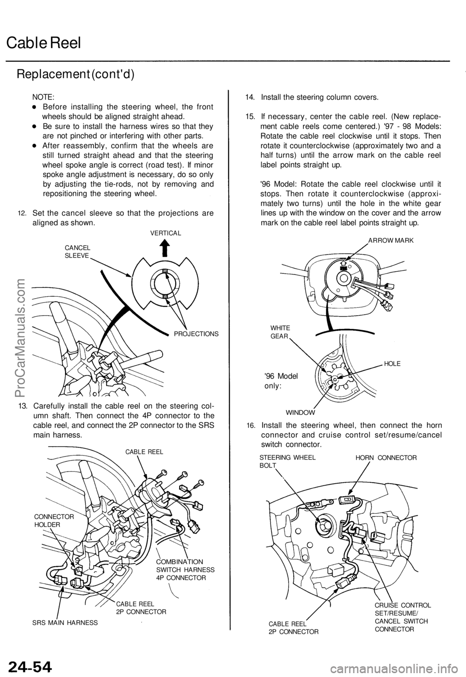
12.
NOTE:
Before installing the steering wheel, the front
wheels should be aligned straight ahead.
Be sure to install the harness wires so that they
are not pinched or interfering with other parts.
After reassembly, confirm that the wheels are
still turned straight ahead and that the steering
wheel spoke angle is correct (road test). If minor
spoke angle adjustment is necessary, do so only
by adjusting the tie-rods, not by removing and
repositioning the steering wheel.
Set the cancel sleeve so that the projections are
aligned as shown.
VERTICAL
CANCEL
SLEEVE
PROJECTIONS
13. Carefully install the cable reel on the steering col-
umn shaft. Then connect the 4P connector to the
cable reel, and connect the 2P connector to the SRS
main harness.
CABLE REEL
CONNECTOR
HOLDER
COMBINATION
SWITCH HARNESS
4P CONNECTOR
CABLE REEL
2P CONNECTOR
SRS MAIN HARNESS
14. Install the steering column covers.
15. If necessary, center the cable reel. (New replace-
ment cable reels come centered.) '97 - 98 Models:
Rotate the cable reel clockwise until it stops. Then
rotate it counterclockwise (approximately two and a
half turns) until the arrow mark on the cable reel
label points straight up.
'96 Model: Rotate the cable reel clockwise until it
stops. Then rotate it counterclockwise (approxi-
mately two turns) until the hole in the white gear
lines up with the window on the cover and the arrow
mark on the cable reel label points straight up.
ARROW MARK
WHITE
GEAR
'96 Model
only:
HOLE
16.
WINDOW
Install the steering wheel, then connect the horn
connector and cruise control set/resume/cancel
switch connector.
STEERING WHEEL
BOLT
HORN CONNECTOR
CABLE REEL
2P CONNECTOR
CRUISE CONTROL
SET/RESUME/
CANCEL SWITCH
CONNECTORProCarManuals.com
Page 1354 of 1771
Door Panel/Plastic Cover Replacement
NOTE: Take care not to scratch the door panel and other
parts.
1. Pry the cap and remove the screw. Remove the inner
handle trim while pulling the inner handle.
CAP
INNER HANDLE
TRIM
2. Pry the cap and remove the screw. Remove the arm-
rest pocket and disconnect the power window switch
connector.
ARMREST
POCKET
POWER WINDOW
SWITCH CONNECTOR
3. Release the clips that hold the door panel. Disconnect
the courtesy light, then remove the door panel by
pulling it upward.
NOTE: Remove the door panel with as little bending
as possible to avoid creasing or breaking it.
TRIM PAD
REMOVER
SNAP-ON
#A177, or
equivalent
TRIM PAD
REMOVER
DOOR PANEL
COURTESY LIGHT
CONNECTORProCarManuals.com
Page 1381 of 1771
Windshield/Rear Windo w
Index
NOTE : Th e number s afte r th e par t name s sho w th e quantitie s o f th e part s used .
Windshield :
RIGHT SID EMOLDIN G
RUBBER DA M
WINDSHIEL DRemoval, pag e 20-3 7Installation , pag e 20-3 8DEFOGGE RSEAL
UPPE R MOLDIN G
SPACER , 2
(Bod y side ) UPPE
R CLI P A , 4 Whit e
UPPE R CLI P B , 5 Whit e
LEF T SID E
MOLDIN G
SIDE CLI P A , 8 , Purpl e
RETAINER , 8 Orang e
SID E CLI P B , 2 Whit e
SID E CLI P C , 4 Gree n
Rear Window :UPPER
SPACER , 1
REA R WINDO W (Glas s side )
Removal , pag e 20-4 3
Installation , pag e 20-4 4
LOWE R SPACER , 2
(Bod y side )
RIGH T REA R WINDO W
MOLDING
RIGHTLOWE RCOVER
MOLDIN GHOLDER , 8 TERMINA
L
BAS E COVE R
TERMINA LCOVER
RUBBE R DA M
CLI P A , 1 2 Whit e
LEF T REA R WINDO W
MOLDING
LEFT LOWE R
COVE R CLI
P B , 1 6 Re d
ProCarManuals.com
Page 1388 of 1771

Windshield
Installation (cont'd )
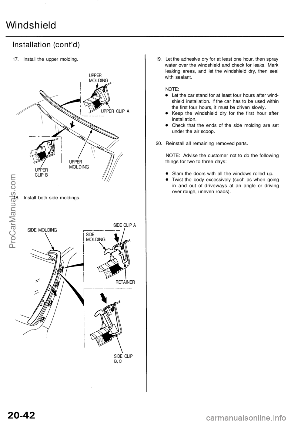
17. Instal l th e uppe r molding .
UPPERMOLDIN G
UPPER CLI P A
UPPE R
CLI P B
18 . Instal l bot h sid e moldings .
SIDE CLI P ASID E MOLDIN G
RETAINE R
SID E CLI P
B, C
19 . Le t th e adhesiv e dr y fo r a t leas t on e hour , the n spra y
wate r ove r th e windshiel d an d chec k fo r leaks . Mar k
leakin g areas , an d le t th e windshiel d dry , the n sea l
wit h sealant .
NOTE:
Let th e ca r stan d fo r a t leas t fou r hour s afte r wind -
shiel d installation . I f th e ca r ha s t o b e use d withi n
th e firs t fou r hours , i t mus t b e drive n slowly .
Kee p th e windshiel d dr y fo r th e firs t hou r afte r
installation .
Chec k tha t th e end s o f th e sid e moldin g ar e se t
unde r th e ai r scoop .
20 . Reinstal l al l remainin g remove d parts .
NOTE : Advis e th e custome r no t t o d o th e followin g
thing s fo r tw o t o thre e days :
Sla m th e door s wit h al l th e window s rolle d up .
Twis t th e bod y excessivel y (suc h a s whe n goin g
i n an d ou t o f driveway s a t a n angl e o r drivin g
ove r rough , uneve n roads) .
UPPERMOLDIN G
SIDEMOLDIN G
ProCarManuals.com
Page 1389 of 1771

Rear Windo w
Remova l
CAUTION :
Wea r glove s t o remov e an d instal l th e rea r window .
Us e sea t cover s to avoi d damagin g an y surfaces .
D o no t damag e th e rea r windo w defogge r gri d lines ,
windo w antenn a gri d lines , an d terminals .
1 . T o remov e th e rea r window , firs t remov e the :
Trun k li d (se e pag e 20-100 )
Rea r sea t cushio n an d seat-bac k (se e pag e 20-85 )
Rea r pilla r tri m (se e pag e 20-59 )
Rea r shel f (se e pag e 20-59 )
2 . Pul l dow n th e rea r o f th e headline r (se e pag e 20-61 ).
CAUTION : Tak e car e no t t o ben d th e headline r exces -
sively.
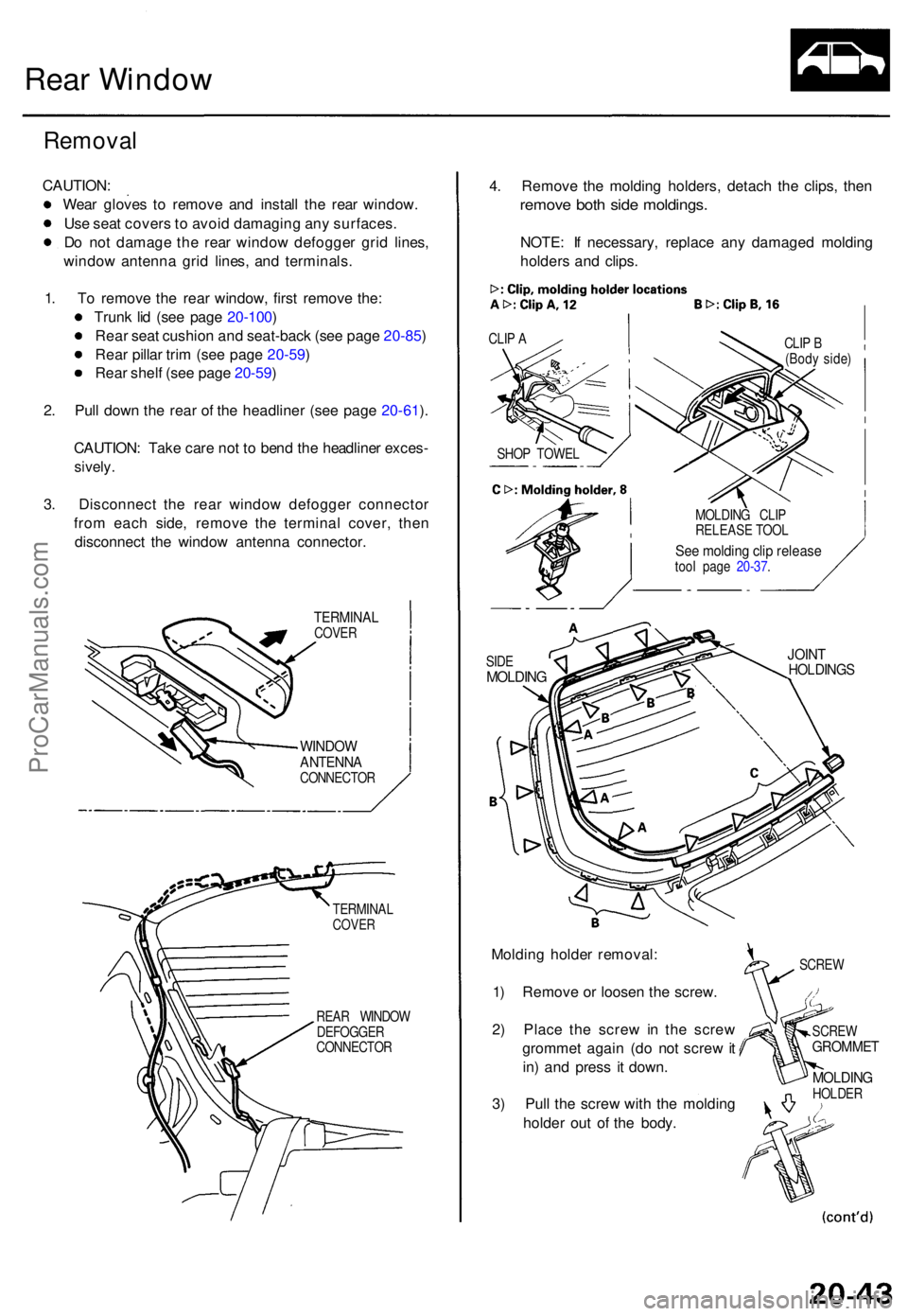
3. Disconnec t th e rea r windo w defogge r connecto r
fro m eac h side , remov e th e termina l cover , the n
disconnec t th e windo w antenn a connector .
TERMINALCOVER
WINDO WANTENN ACONNECTO R
4. Remov e th e moldin g holders , detac h th e clips , the n
remov e bot h sid e moldings .
NOTE: I f necessary , replac e an y damage d moldin g
holder s an d clips .
CLIP A
Moldin g holde r removal :
1 ) Remov e o r loose n th e screw .
2 ) Plac e th e scre w in th e scre w
gromme t agai n (d o no t scre w it
in ) an d pres s i t down .
3 ) Pul l th e scre w wit h th e moldin g
holde r ou t o f th e body .
SCRE WGROMME T
MOLDINGHOLDER
TERMINA
L
COVER
REAR WINDO W
DEFOGGE R
CONNECTO R SCRE
W
JOINTHOLDING SSIDEMOLDIN G
MOLDIN G CLI P
RELEAS E TOO L
See moldin g cli p releas etool pag e 20-37 .CLI
P B
(Bod y side )
SHO P TOWE L
ProCarManuals.com
Page 1390 of 1771
Rear Window
Removal (cont'd)
5. Remove the other clips from the body.
6. Apply protective tape to along the edge of the body
as shown. Using as awl, make a hole through the
rubber dam and adhesive from inside the car. Push
the piano wire through the hole, and wrap each end
around a piece of wood.
PIANO WIRE
ADHESIVE
REAR WINDOW
PROTECTIVE
TAPE
7.
PROTECTIVE
TAPE
PROTECTIVE
TAPE
RUBBER
DAM
ADHESIVE
With a helper on the outside, pull the piano wire
back and forth in a sawing motion, and carefully cut
through the rubber dam and adhesive around the
entire rear window.
CAUTION: Hold the piano wire as close to the rear
window as possible to prevent damage to the body.
REAR
WINDOW
LOWER
SPACERS
8. Carefully remove the rear window.
9. Cut the lower spacers away from the body with a
knife.
NOTE: Replace the lower spacers with new ones
whenever the rear window is removed.
PIANO WIRE
SPACER
PIANO
WIREProCarManuals.com
Page 1392 of 1771
4. Glu e th e rubbe r da m to th e insid e fac e o f th e rea r
window , a s shown , t o contai n th e adhesiv e durin g
installation , an d glu e th e uppe r space r a s shown .
NOTE : B e carefu l no t t o touc h th e rea r windo w
wher e adhesiv e wil l b e applied .
10 m m (0.3 9 in)UPPE RSPACE R
The rubbe r da m ca n exten dinto this area .
45 m m(1. 8 in )9 m m(0. 4 in)
Do no t glu e th e rubbe rdam acros s th e printe ddots.
RUBBE RDAM TERMINA LBASE COVE R
ALIGNMEN TMARK
RUBBE RDAM
RUBBE RDAM
REA RWINDO W
5. Instal l th e clips , an d glu e th e lowe r spacer s t o th e
bod y a s shown .
6 . Se t th e rea r windo w o n th e lowe r spacers , the n cente r
i t i n th e opening . Mak e alignmen t mark s acros s th e
rea r windo w an d bod y wit h a greas e penci l a t th e fou r
point s shown .
ALIGNMEN T MAR K
REARWINDO W
LOWER SPACER S
7. Remov e th e rea r window .
UPPER -SPACE R
ALIGNMEN TMARKS
RUBBE RDAM
GLAS S
ProCarManuals.com
Page 1393 of 1771

Rear Window
Installation (cont'd)
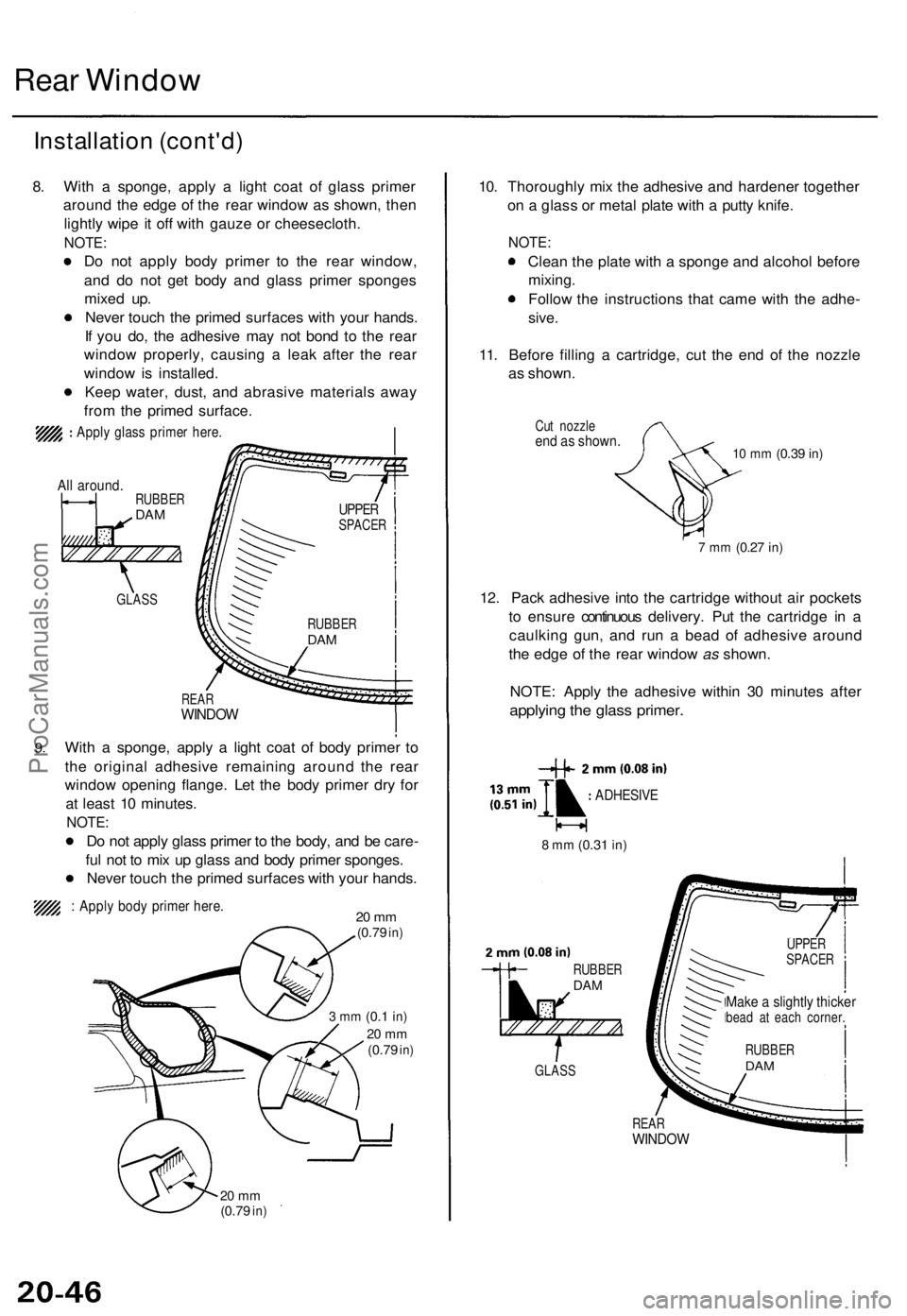
8. With a sponge, apply a light coat of glass primer
around the edge of the rear window as shown, then
lightly wipe it off with gauze or cheesecloth.
NOTE:
Do not apply body primer to the rear window,
and do not get body and glass primer sponges
mixed up.
Never touch the primed surfaces with your hands.
If you do, the adhesive may not bond to the rear
window properly, causing a leak after the rear
window is installed.
Keep water, dust, and abrasive materials away
from the primed surface.
Apply glass primer here.
All around.
9.
REAR
WINDOW
With a sponge, apply a light coat of body primer to
the original adhesive remaining around the rear
window opening flange. Let the body primer dry for
at least 10 minutes.
NOTE:
Do not apply glass primer to the body, and be care-
ful not to mix up glass and body primer sponges.
Never touch the primed surfaces with your hands.
: Apply body primer here.
20 mm
(0.79
in)
3 mm
(0.1
in)
20 mm
(0.79
in)
20 mm
(0.79
in)
10. Thoroughly mix the adhesive and hardener together
on a glass or metal plate with a putty knife.
NOTE:
Clean the plate with a sponge and alcohol before
mixing.
Follow the instructions that came with the adhe-
sive.
11. Before filling a cartridge, cut the end of the nozzle
as shown.
Cut nozzle
end as shown.
10 mm
(0.39
in)
7 mm
(0.27
in)
12. Pack adhesive into the cartridge without air pockets
to ensure continuous delivery. Put the cartridge in a
caulking gun, and run a bead of adhesive around
the edge of the rear window as shown.
NOTE: Apply the adhesive within 30 minutes after
applying the glass primer.
8 mm
(0.31
in)
REAR
WINDOW
GLASS
RUBBER
DAM
ADHESIVE
UPPER
SPACER
RUBBER
DAM
Make a slightly thicker
bead at each corner.
GLASS
RUBBER
DAM
RUBBER
DAM
UPPER
SPACERProCarManuals.com