Page 158 of 1771
System Description
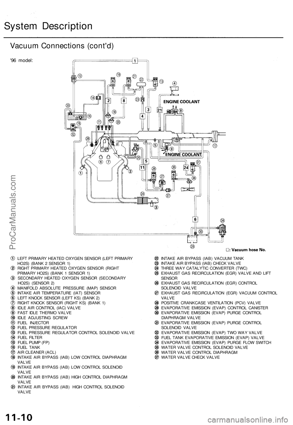
Vacuum Connections (cont'd)
'96 model:
LEFT PRIMARY HEATED OXYGEN SENSOR (LEFT PRIMARY
HO2S) (BANK 2 SENSOR 1)
RIGHT PRIMARY HEATED OXYGEN SENSOR (RIGHT
PRIMARY HO2S) (BANK 1 SENSOR 1)
SECONDARY HEATED OXYGEN SENSOR (SECONDARY
HO2S) (SENSOR 2)
MANIFOLD ABSOLUTE PRESSURE (MAP) SENSOR
INTAKE AIR TEMPERATURE (IAT) SENSOR
LEFT KNOCK SENSOR (LEFT KS) (BANK 2)
RIGHT KNOCK SENSOR (RIGHT KS) (BANK 1)
IDLE AIR CONTROL (IAC) VALVE
FAST IDLE THERMO VALVE
IDLE ADJUSTING SCREW
FUEL INJECTOR
FUEL PRESSURE REGULATOR
FUEL PRESSURE REGULATOR CONTROL SOLENOID VALVE
FUEL FILTER
FUEL PUMP (FP)
FUEL TANK
AIR CLEANER (ACL)
INTAKE AIR BYPASS (IAB) LOW CONTROL DIAPHRAGM
VALVE
INTAKE AIR BYPASS (IAB) LOW CONTROL SOLENOID
VALVE
INTAKE AIR BYPASS (IAB) HIGH CONTROL DIAPHRAGM
VALVE
INTAKE AIR BYPASS (IAB) HIGH CONTROL SOLENOID
VALVE
INTAKE AIR BYPASS (IAB) VACUUM TANK
INTAKE AIR BYPASS (IAB) CHECK VALVE
THREE WAY CATALYTIC CONVERTER (TWC)
EXHAUST GAS RECIRCULATION (EGR) VALVE AND LIFT
SENSOR
EXHAUST GAS RECIRCULATION (EGR) CONTROL
SOLENOID VALVE
EXHAUST GAS RECIRCULATION (EGR) VACUUM CONTROL
VALVE
POSITIVE CRANKCASE VENTILATION (PCV) VALVE
EVAPORATIVE EMISSION (EVAP) CONTROL CANISTER
EVAPORATIVE EMISSION (EVAP) PURGE CONTROL
DIAPHRAGM VALVE
EVAPORATIVE EMISSION (EVAP) PURGE CONTROL
SOLENOID VALVE
EVAPORATIVE EMISSION (EVAP) TWO WAY VALVE
FUEL TANK EVAPORATIVE EMISSION (EVAP) VALVE
EVAPORATIVE EMISSION (EVAP) PURGE FLOW SWITCH
WATER VALVE CONTROL SOLENOID VALVE
WATER VALVE CONTROL DIAPHRAGM
WATER VALVE CHECK VALVEProCarManuals.com
Page 159 of 1771
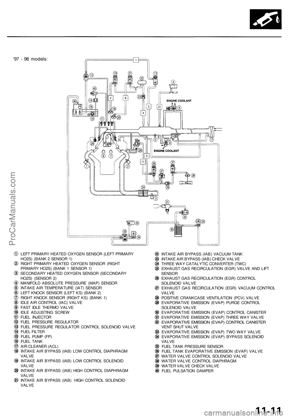
'97 - 98 models:
LEFT PRIMARY HEATED OXYGEN SENSOR (LEFT PRIMARY
HO2S) (BANK 2 SENSOR 1)
RIGHT PRIMARY HEATED OXYGEN SENSOR (RIGHT
PRIMARY HO2S) (BANK 1 SENSOR 1)
SECONDARY HEATED OXYGEN SENSOR (SECONDARY
HO2S) (SENSOR 2)
MANIFOLD ABSOLUTE PRESSURE (MAP) SENSOR
INTAKE AIR TEMPERATURE (IAT) SENSOR
LEFT KNOCK SENSOR (LEFT KS) (BANK 2)
RIGHT KNOCK SENSOR (RIGHT KS) (BANK 1)
IDLE AIR CONTROL (IAC) VALVE
FAST IDLE THERMO VALVE
IDLE ADJUSTING SCREW
FUEL INJECTOR
FUEL PRESSURE REGULATOR
FUEL PRESSURE REGULATOR CONTROL SOLENOID VALVE
FUEL FILTER
FUEL PUMP (FP)
FUEL TANK
AIR CLEANER (ACL)
INTAKE AIR BYPASS (IAB) LOW CONTROL DIAPHRAGM
VALVE
INTAKE AIR BYPASS (IAB) LOW CONTROL SOLENOID
VALVE
INTAKE AIR BYPASS (IAB) HIGH CONTROL DIAPHRAGM
VALVE
INTAKE AIR BYPASS (IAB) HIGH CONTROL SOLENOID
VALVE
INTAKE AIR BYPASS (IAB) VACUUM TANK
INTAKE AIR BYPASS (IAB) CHECK VALVE
THREE WAY CATALYTIC CONVERTER (TWC)
EXHAUST GAS RECIRCULATION (EGR) VALVE AND LIFT
SENSOR
EXHAUST GAS RECIRCULATION (EGR) CONTROL
SOLENOID VALVE
EXHAUST GAS RECIRCULATION (EGR) VACUUM CONTROL
VALVE
POSITIVE CRANKCASE VENTILATION (PCV) VALVE
EVAPORATIVE EMISSION (EVAP) PURGE CONTROL
SOLENOID VALVE
EVAPORATIVE EMISSION (EVAP) CONTROL CANISTER
EVAPORATIVE EMISSION (EVAP) THREE WAY VALVE
EVAPORATIVE EMISSION (EVAP) CONTROL CANISTER
VENT SHUT VALVE
EVAPORATIVE EMISSION (EVAP) TWO WAY VALVE
EVAPORATIVE EMISSION (EVAP) BYPASS SOLENOID
VALVE
FUEL TANK PRESSURE SENSOR
FUEL TANK EVAPORATIVE EMISSION (EVAP) VALVE
WATER VALVE CONTROL SOLENOID VALVE
WATER VALVE CONTROL DIAPHRAGM
WATER VALVE CHECK VALVE
FUEL PULSATION DAMPERProCarManuals.com
Page 220 of 1771
NOTE: Check all hose clamps and retighten if necessary.
'96 model:
To
FUEL
PRESSURE
REGULATOR
FUEL GAUGE SENDING
UNIT ASSEMBLY
FUEL
' FILTER
EVAPORATIVE EMISSION
(EVAP) TWO WAY VALVE
FUEL PUMP
ASSEMBLY
EVAPORATIVE EMISSION
(EVAP) CONTROL
CANISTER
10-15
mm
(0.39
-
0.59
in)
Clamp in the middle.
Clamp in the middle.
O-RING
Replace.
O-RING
Replace.
FUEL
TANKProCarManuals.com
Page 221 of 1771
Fuel Supply System
Fuel Lines (cont'd)
'97 - 98 models:
To
FUEL
PRESSURE
REGULATOR
FUEL
FILTER
FUEL GAUGE SENDING
UNIT ASSEMBLY
BASE GASKET
Replace.
FUEL PUMP
ASSEMBLY
EVAPORATIVE EMISSION
(EVAP) TWO WAY VALVE
EVAPORATIVE EMISSION
(EVAP) CONTROL
CANISTER
10- 15 mm
(0.39-0.59 in)
Clamp in the middle.
Clamp in the middle.
FUEL
TANKProCarManuals.com
Page 223 of 1771
Fuel Pressure
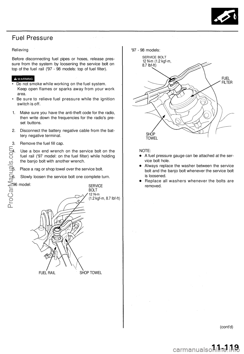
Relieving
Before disconnectin g fue l pipe s o r hoses , releas e pres -
sure fro m th e syste m b y loosenin g th e servic e bol t o n
top o f th e fue l rai l ('9 7 - 9 8 models : to p o f fue l filter) .
• D o no t smok e whil e workin g o n th e fue l system .
Kee p ope n flame s o r spark s awa y fro m you r wor k
area.
• B e sur e t o reliev e fue l pressur e whil e th e ignitio n
switc h is off .
1 . Mak e sur e yo u hav e th e anti-thef t cod e fo r th e radio ,
the n writ e dow n th e frequencie s fo r th e radio' s pre -
se t buttons .
2 . Disconnec t th e batter y negativ e cabl e fro m th e bat -
ter y negativ e terminal .
3 . Remov e th e fue l fil l cap .
4 . Us e a bo x en d wrenc h o n th e servic e bol t o n th e
fue l rai l ('9 7 model : o n th e fue l filter ) whil e holdin g
th e banj o bol t wit h anothe r wrench .
5 . Plac e a ra g o r sho p towe l ove r th e servic e bolt .
6 . Slowl y loose n th e servic e bol t on e complet e turn .
'9 6 model :
SERVIC EBOLT12 N- m(1.2 kgf-m , 8. 7 Ibf-ft )
FUE L RAI L SHO
P TOWE L
'97 - 9 8 models :
SERVICE BOL T12 N- m (1. 2 kgf-m ,8.7 Ibf-ft )
FUELFILTE R
SHOP
TOWE L
NOTE:
A fue l pressur e gaug e ca n b e attache d a t th e ser -
vic e bol t hole .
Alway s replac e th e washe r betwee n th e servic e
bol t an d th e banj o bol t wheneve r th e servic e bol t
i s loosened .
Replac e al l washer s wheneve r th e bolt s ar e
removed .
(cont'd)
ProCarManuals.com
Page 224 of 1771
Fuel Suppl y Syste m
Fuel Pressur e (cont'd )
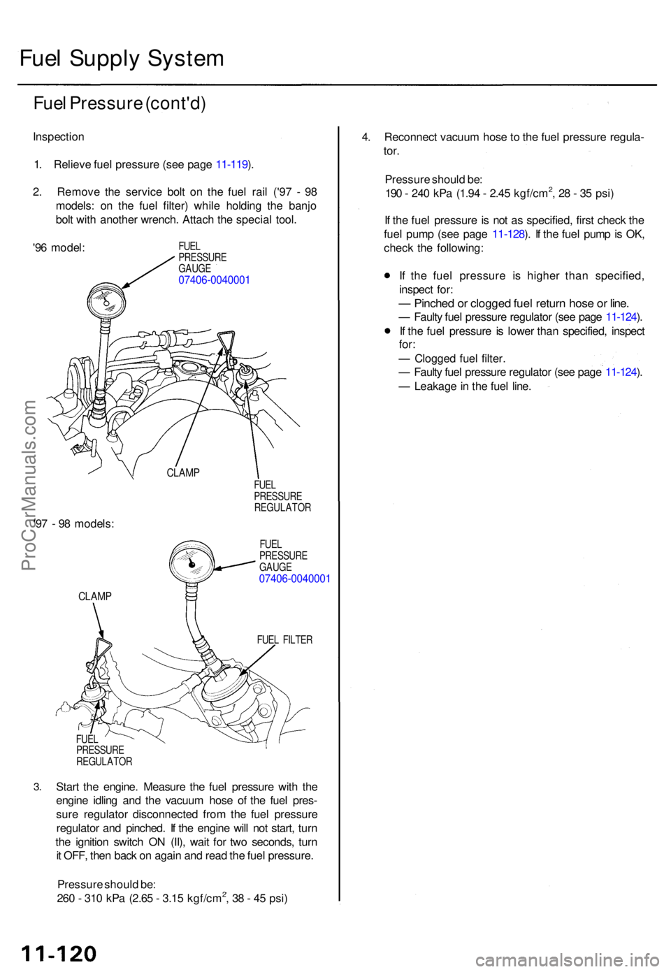
Inspectio n
1 . Reliev e fue l pressur e (se e pag e 11-119 ).
2 . Remov e th e servic e bol t o n th e fue l rai l ('9 7 - 9 8
models : o n th e fue l filter ) whil e holdin g th e banj o
bol t wit h anothe r wrench . Attac h th e specia l tool .
'9 6 model :
FUEL
PRESSUR E
GAUG E
07406-004000 1
CLAMP
'97 - 9 8 models :
CLAMP
FUEL
PRESSUR E
REGULATO R
FUE L
PRESSUR E
GAUG E
07406-004000 1
FUEL FILTE R
3.
FUE L
PRESSUR E
REGULATO R
Start th e engine . Measur e th e fue l pressur e wit h th e
engin e idlin g an d th e vacuu m hos e o f th e fue l pres -
sur e regulato r disconnecte d fro m th e fue l pressur e
regulato r an d pinched . I f th e engin e wil l no t start , tur n
th e ignitio n switc h O N (II) , wai t fo r tw o seconds , tur n
i t OFF , the n bac k o n agai n an d rea d th e fue l pressure .
Pressur e shoul d be :
26 0 - 31 0 kP a (2.6 5 - 3.1 5 kgf/cm
2, 3 8 - 4 5 psi ) 4
. Reconnec t vacuu m hos e t o th e fue l pressur e regula -
tor.
Pressur e shoul d be :
19 0 - 24 0 kP a (1.9 4 - 2.4 5 kgf/cm2, 2 8 - 3 5 psi )
I f th e fue l pressur e is no t a s specified , firs t chec k th e
fue l pum p (se e pag e 11-128 ). I f th e fue l pum p is OK ,
chec k th e following :
I f th e fue l pressur e i s highe r tha n specified ,
inspec t for :
— Pinche d o r clogge d fue l retur n hos e o r line .
— Fault y fue l pressur e regulato r (se e pag e 11-124 ).
I f th e fue l pressur e i s lowe r tha n specified , inspec t
for:
— Clogge d fue l filter .
— Fault y fue l pressur e regulato r (se e pag e 11-124 ).
— Leakag e in th e fue l line .
ProCarManuals.com
Page 227 of 1771
14. Align the center line on the connector with the mark on the fuel rail.
15. Install and tighten the retainer nuts.
16. Connect the fuel hose to the fuel rail.
17. Connect the vacuum hose and fuel return hose to the fuel pressure regulator.
18. Install the connectors on the fuel injectors.
19. Install the engine cover.
20. Turn the ignition switch ON (ll) but do not operate the starter. After the fuel pump runs for approximately two seconds,
the fuel pressure in the fuel line rises. Repeat this two or three times, then check whether there is any fuel leakage.
FUEL
INJECTOR
MARKINGS
FUEL
RAIL
FUEL RAIL
INSULATOR
FUEL
RAILSProCarManuals.com
Page 253 of 1771
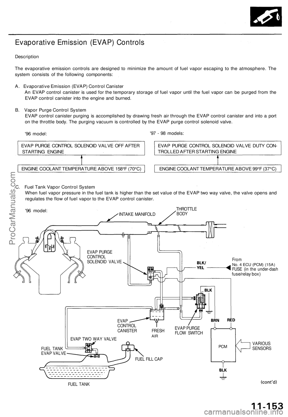
Evaporative Emission (EVAP) Controls
Description
The evaporative emission controls are designed to minimize the amount of fuel vapor escaping to the atmosphere. The
system consists of the following components:
A. Evaporative Emission (EVAP) Control Canister
An EVAP control canister is used for the temporary storage of fuel vapor until the fuel vapor can be purged from the
EVAP control canister into the engine and burned.
B. Vapor Purge Control System
EVAP control canister purging is accomplished by drawing fresh air through the EVAP control canister and into a port
on the throttle body. The purging vacuum is controlled by the EVAP purge control solenoid valve.
'96 model:
'97 - 98 models:
C. Fuel Tank Vapor Control System
When fuel vapor pressure in the fuel tank is higher than the set value of the EVAP two way valve, the valve opens and
regulates the flow of fuel vapor to the EVAP control canister.
'96 model:
INTAKE MANIFOLD
THROTTLE
BODY
EVAP PURGE
CONTROL
SOLENOID VALVE
FUEL TANK
EVAP VALVE
EVAP TWO WAY VALVE
From
No. 4 ECU
(PCM) (15A)
FUSE (in the under-dash
fuse/relay box)
EVAP
CONTROL
CANISTER FRESH
AIR
EVAP PURGE
FLOW SWITCH
FUEL FILL CAP
PCM
VARIOUS
SENSORS
FUEL TANK
ENGINE COOLANT TEMPERATURE ABOVE 158°F (70°C)
ENGINE COOLANT TEMPERATURE ABOVE 99°F (37°C)
EVAP PURGE CONTROL SOLENOID VALVE DUTY CON-
TROLLED AFTER STARTING ENGINE
EVAP PURGE CONTROL SOLENOID VALVE OFF AFTER
STARTING ENGINEProCarManuals.com