1995 ACURA TL charging
[x] Cancel search: chargingPage 199 of 1771
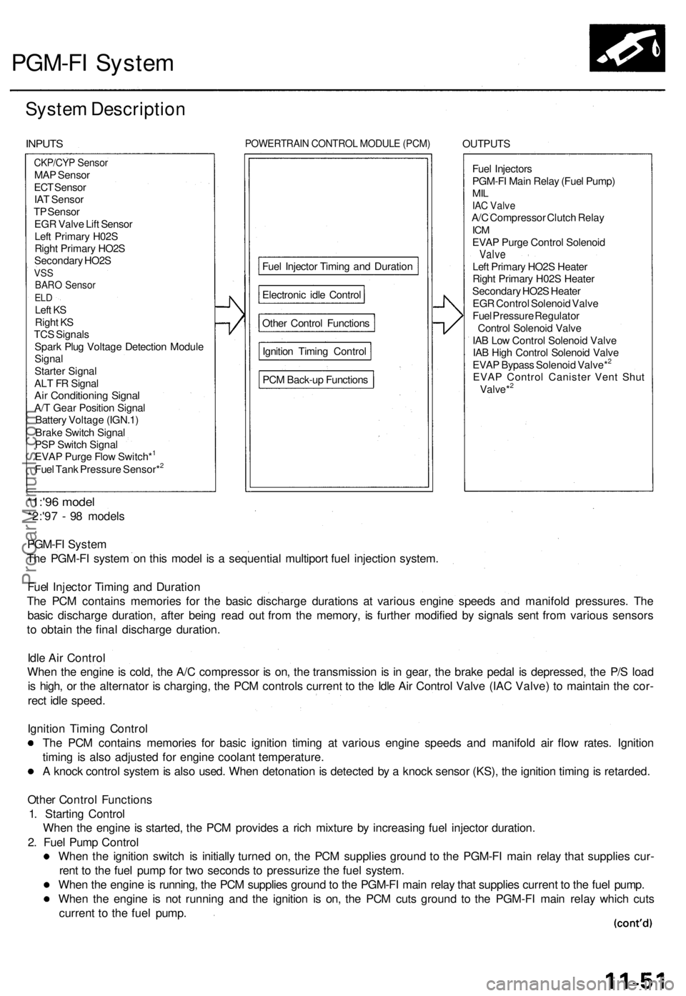
PGM-FI Syste m
System Descriptio n
INPUTS POWERTRAI N CONTRO L MODUL E (PCM ) OUTPUT S
Fue l Injector s
PGM-F I Mai n Rela y (Fue l Pump )
MILIAC Valv eA/C Compresso r Clutc h Rela yICMEVA P Purg e Contro l Solenoi dValveLeft Primar y HO2 S Heate r
Righ t Primar y H02 S Heate r
Secondar y HO2 S Heate r
EG R Contro l Solenoi d Valv e
Fue l Pressur e Regulato r
Contro l Solenoi d Valv e
IA B Lo w Contro l Solenoi d Valv e
IA B Hig h Contro l Solenoi d Valv e
EVA P Bypas s Solenoi d Valve*
2
EVA P Contro l Caniste r Ven t Shu t
Valve*2
*1:'9 6 mode l
*2:'97 - 9 8 model s
PGM-F I Syste m
Th e PGM-F I syste m o n thi s mode l i s a sequentia l multipor t fue l injectio n system .
Fue l Injecto r Timin g an d Duratio n
Th e PC M contain s memorie s fo r th e basi c discharg e duration s a t variou s engin e speed s an d manifol d pressures . Th e
basi c discharg e duration , afte r bein g rea d ou t fro m th e memory , i s furthe r modifie d b y signal s sen t fro m variou s sensor s
t o obtai n th e fina l discharg e duration .
Idl e Ai r Contro l
Whe n th e engin e is cold , th e A/ C compresso r i s on , th e transmissio n i s i n gear , th e brak e peda l i s depressed , th e P/ S loa d
i s high , o r th e alternato r i s charging , th e PC M control s curren t t o th e Idl e Ai r Contro l Valv e (IA C Valve ) t o maintai n th e cor -
rec t idl e speed .
Ignitio n Timin g Contro l
Th e PC M contain s memorie s fo r basi c ignitio n timin g a t variou s engin e speed s an d manifol d ai r flo w rates . Ignitio n
timin g i s als o adjuste d fo r engin e coolan t temperature .
A knoc k contro l syste m is als o used . Whe n detonatio n is detecte d b y a knoc k senso r (KS) , th e ignitio n timin g is retarded .
Othe r Contro l Function s
1 . Startin g Contro l
Whe n th e engin e is started , th e PC M provide s a ric h mixtur e b y increasin g fue l injecto r duration .
2 . Fue l Pum p Contro l
Whe n th e ignitio n switc h i s initiall y turne d on , th e PC M supplie s groun d t o th e PGM-F I mai n rela y tha t supplie s cur -
ren t t o th e fue l pum p fo r tw o second s t o pressuriz e th e fue l system .
Whe n th e engin e is running , th e PC M supplie s groun d to th e PGM-F I mai n rela y tha t supplie s curren t t o th e fue l pump .
Whe n th e engin e i s no t runnin g an d th e ignitio n i s on , th e PC M cut s groun d t o th e PGM-F I mai n rela y whic h cut s
curren t t o th e fue l pump .
CKP/CY P Senso rMAP Senso r
EC T Senso r
IA T Senso r
T P Senso r
EG R Valv e Lif t Senso r
Lef t Primar y H02 S
Righ t Primar y HO2 S
Secondar y HO2 S
VSSBAR O Senso rELDLef t K S
Righ t K S
TC S Signal s
Spar k Plu g Voltag e Detectio n Modul e
Signa l
Starte r Signa l
AL T F R Signa l
Air Conditionin g Signa lA/T Gea r Positio n Signa l
Batter y Voltag e (IGN.1 )
Brak e Switc h Signa l
PS P Switc h Signa l
EVA P Purg e Flo w Switch*
1
Fue l Tan k Pressur e Sensor*2
PC M Back-u p Function s
Ignitio
n Timin g Contro l
Othe
r Contro l Function s
Electroni
c idl e Contro l
Fue
l Injecto r Timin g an d Duratio n
ProCarManuals.com
Page 209 of 1771
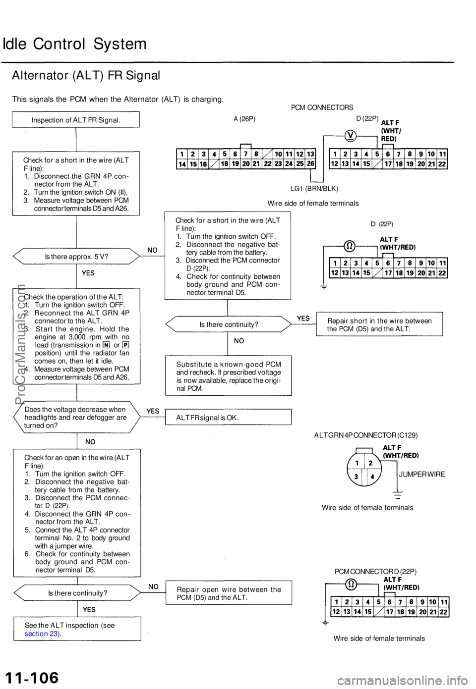
Idle Contro l Syste m
Alternato r (ALT ) F R Signa l
This signal s th e PC M whe n th e Alternato r (ALT ) i s charging .
Is ther e approx . 5 V ?
Chec k th e operatio n o f th e ALT :
1 . Tur n th e ignitio n switc h OFF .
2 . Reconnec t th e AL T GR N 4 P
connecto r t o th e ALT .
3 . Star t th e engine . Hol d th e
engin e a t 3,00 0 rp m wit h n o
loa d (transmissio n in o r
position ) unti l th e radiato r fa n
come s on , the n le t i t idle .
4 . Measur e voltag e betwee n PC M
connecto r terminal s D 5 an d A26 .
Doe s th e voltag e decreas e whe n
headlight s an d rea r defogge r ar e
turne d on ?
Chec k fo r a n ope n in th e wir e (AL T
F line) :
1 . Tur n th e ignitio n switc h OFF .
2 . Disconnec t th e negativ e bat -
ter y cabl e fro m th e battery .
3 . Disconnec t th e PC M connec -
tor D (22P) .4. Disconnec t th e GR N 4 P con -
necto r fro m th e ALT .
5 . Connec t th e AL T 4 P connecto r
termina l No . 2 to bod y groun d
with a jumpe r wire .6. Chec k fo r continuit y betwee n
bod y groun d an d PC M con -
necto r termina l D5 .
I s ther e continuity ?
Se e th e AL T inspectio n (se e
sectio n 23 ).
PC M CONNECTOR S
A (26P)D (22P )
LG1 (BRN/BLK )
Wire sid e o f femal e terminal s
Chec k fo r a shor t i n th e wir e (AL T
F line) :1. Tur n th e ignitio n switc h OFF .
2 . Disconnec t th e negativ e bat -
ter y cabl e fro m th e battery .
3 . Disconnec t th e PC M connecto r
D (22P) .4. Chec k fo r continuit y betwee n
bod y groun d an d PC M con -
necto r termina l D5 .
D (22P )
Is ther e continuity ? Repai
r shor t i n th e wir e betwee nthe PC M (D5 ) and th e ALT .
Substitut e a known-goo d PC M
an d recheck . I f prescribe d voltag e
i s no w available , replac e th e origi -
nal PCM .
ALT F R signa l i s OK .
ALT GR N 4P CONNECTO R (C129 )
JUMPE R WIR E
Wir e sid e o f femal e terminal s
Repai r ope n wir e betwee n th e
PC M (D5 ) and th e ALT .
Wire sid e o f femal e terminal s
PC
M CONNECTO R D (22P )
Chec
k fo r a shor t i n th e wir e (AL T
F line) :
1 . Disconnec t th e GR N 4 P con -
necto r fro m th e ALT .
2 . Tur n th e ignitio n switc h O N (II) .
3 . Measur e voltag e betwee n PC M
connecto r terminal s D 5 an d A26 .
Inspectio
n o f AL T F R Signal .
ProCarManuals.com
Page 564 of 1771
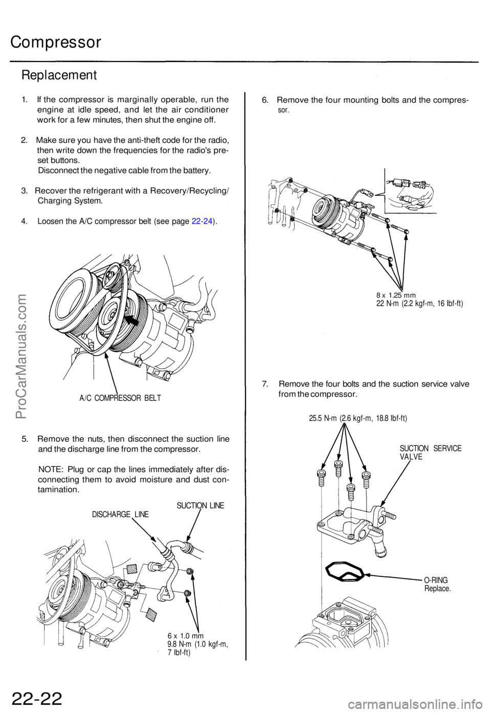
Compressor
Replacemen t
1. I f th e compresso r i s marginall y operable , ru n th e
engin e a t idl e speed , an d le t th e ai r conditione r
wor k fo r a fe w minutes , the n shu t th e engin e off .
2 . Mak e sur e yo u hav e th e anti-thef t cod e fo r th e radio ,
the n writ e dow n th e frequencie s fo r th e radio' s pre -
se t buttons .
Disconnec t th e negativ e cabl e fro m th e battery .
3 . Recove r th e refrigeran t wit h a Recovery/Recycling /
Charging System .
4. Loose n th e A/ C compresso r bel t (se e pag e 22-24 ).
A/ C COMPRESSO R BEL T
5. Remov e th e nuts , the n disconnec t th e suctio n lin e
an d th e discharg e lin e fro m th e compressor .
NOTE : Plu g o r cap the line s immediatel y afte r dis -
connectin g the m to avoi d moistur e an d dus t con -
tamination .
SUCTION LIN EDISCHARG E LIN E
6 x 1. 0 m m9.8 N- m (1. 0 kgf-m ,
7 Ibf-ft )
6. Remov e th e fou r mountin g bolt s an d th e compres -
sor.
8 x 1.2 5 mm22 N- m (2. 2 kgf-m , 1 6 Ibf-ft )
7. Remov e th e fou r bolt s an d th e suctio n servic e valv e
fro m th e compressor .
25.5 N- m (2. 6 kgf-m , 18. 8 Ibf-ft )
SUCTIO N SERVIC E
VALVE
O-RIN G
Replace .
22-22ProCarManuals.com
Page 567 of 1771
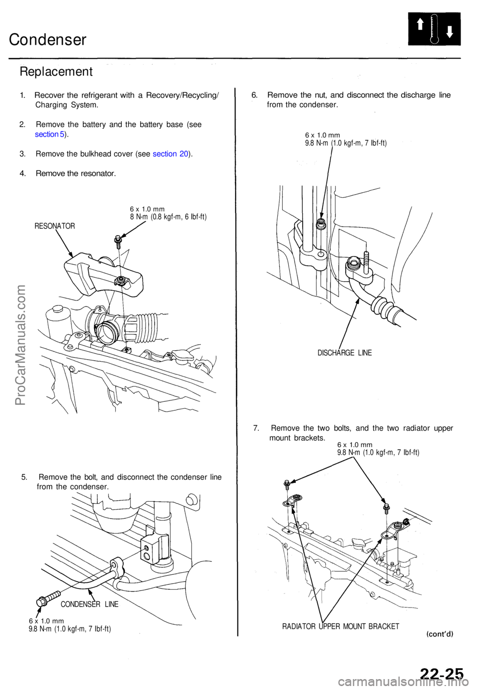
Condenser
Replacemen t
1. Recove r th e refrigeran t wit h a Recovery/Recycling /
Charging System .
2 . Remov e th e batter y an d th e batter y bas e (se e
sectio n 5 ).
3 . Remov e th e bulkhea d cove r (se e sectio n 20 ).
4 . Remov e th e resonator .
6 x 1. 0 m m8 N- m (0. 8 kgf-m , 6 Ibf-ft )
RESONATO R
5. Remov e th e bolt , an d disconnec t th e condense r lin e
fro m th e condenser .
6 x 1. 0 m m9.8 N- m (1. 0 kgf-m , 7 Ibf-ft )
6. Remov e th e nut , an d disconnec t th e discharg e lin e
from th e condenser .
6 x 1. 0 m m9.8 N- m (1. 0 kgf-m , 7 Ibf-ft )
DISCHARG E LIN E
7. Remov e th e tw o bolts , an d th e tw o radiato r uppe r
moun t brackets .
6 x 1. 0 m m9.8 N- m (1. 0 kgf-m , 7 Ibf-ft )
RADIATO R UPPE R MOUN T BRACKE T
CONDENSE
R LIN E
ProCarManuals.com
Page 569 of 1771
A/C Service Tips and Precautions
The air
conditioner system uses
HFC-134a
(R-134a)
refrigerant
and
polyalkyleneglycol (PAG) refrigerant
oil*,
which
are not
compatible with CFC-12 (R-12) refrigerant and mineral oil. Do not use R-12 refrigerant or mineral oil in this system, and do
not attempt to use R-12 servicing equipment; damage to the air conditioner system or your servicing equipment will result.
*DENSO ND-OIL 8:
P/N 38897 - PR7 - A01AH: 120 (4 fl-oz, 4.2 Imp-oz)
P/N 38899 - PR7 - A01: 40 (1 1/3 fl-oz, 1.4 Imp-oz)
Use only service equipment that is U.L.-listed and is certified to meet the requirements of SAE J2210 to remove R-134a
from the air conditioner system.
CAUTION: Exposure to air conditioner refrigerant and lubricant vapor or mist can irritate eyes, nose and throat. Avoid
breathing the air conditioner refrigerant and lubricant vapor or mist.
If accidental system discharge occurs, ventilate work area before resuming service.
R-134a service equipment or vehicle air conditioner systems should not be pressure tested or leak tested with compressed
air.
Some mixtures of air and R-134a have been shown to be combustible at elevated pressures and can result
in tire or explosion causing injury or property damage. Never use compressed air to pressure test R-134a service equip-
ment or vehicle air conditioner systems.
Additional health and safety information may be obtained from the refrigerant and lubricant manufacturers.
1. Always disconnect the negative cable from the battery whenever replacing air conditioning parts.
2. Keep moisture and dust out of the system. When disconnecting any lines, plug or cap the fittings immediately; don't
remove the caps or plugs until just before you reconnect each line.
3. Before connecting any hose or line, apply a few drops of refrigerant oil to the O-ring.
4. When tightening or loosening a fitting, use a second wrench to support the matching fitting.
5. When discharging the system, use a R-134a refrigerant Recovery/Recycling/Charging System; don't release refriger-
ant into the atmosphere.
6. Add refrigerant oil after replacing the following parts:
NOTE:
To avoid contamination, do not return the oil to the container once dispensed, and never mix it with other refriger-
ant oils.
Immediately after using the oil, replace the cap on the container, and seal it to avoid moisture absorption.
Do not spill the refrigerant oil on the vehicle; it may damage the paint; if the refrigerant oil contacts the paint, wash
it off immediately.
Condenser ........................................ 25 (5/6 fl-oz, 0.9 Imp-oz)
Evaporator........................................ 50 (1 2/3 fl-oz, 1.8 Imp-oz)
Line or hose ...................................... 20 (2/3 fl-oz, 0.7 Imp-oz)
Receiver/Dryer
.................................
15
(1/2
fl-oz,
0.5
Imp-oz)
Leakage repair ................................. 25 (5/6 fl-oz, 0.9 Imp-oz)
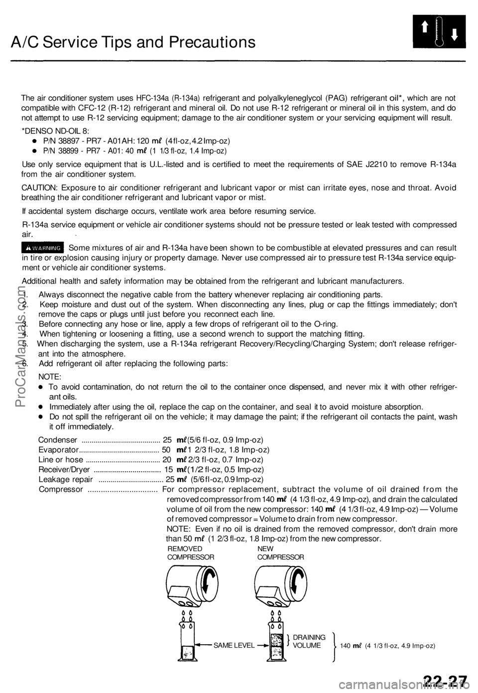
Compressor ................................ For compressor replacement, subtract the volume of oil drained from the
removed compressor from 140 (4 1/3 fl-oz, 4.9 Imp-oz), and drain the calculated
volume of oil from the new compressor: 140 (4 1/3 fl-oz, 4.9 Imp-oz) — Volume
of removed compressor = Volume to drain from new compressor.
NOTE: Even if no oil is drained from the removed compressor, don't drain more
than 50 (1 2/3 fl-oz, 1.8 Imp-oz) from the new compressor.
REMOVED NEW
COMPRESSOR COMPRESSOR
SAME LEVEL
140 (4 1/3 fl-oz, 4.9 Imp-oz)
DRAINING
VOLUMEProCarManuals.com
Page 570 of 1771
A/C System Service
Performance Test
The performance test will help determine if the air con-
ditioner system is operating within specifications.
Use only service equipment that is U.L.-listed and is cer-
tified to meet the requirements of SAE J2210 to remove
HFC-134a (R-134a) from the air conditioner system.
CAUTION: Exposure to air conditioner refrigerant and
lubricant vapor or mist can irritate eyes, nose and
throat. Avoid breathing the air conditioner refrigerant
and lubricant vapor or mist.
If accidental system discharge occurs, ventilate work
area before resuming service.
R-134a service equipment or vehicle air conditioner sys-
tems should not be pressure tested or leak tested with
compressed air.
Some mixtures of air and R-134a have been
shown to be combustible at elevated pressures and can
result in fire or explosion causing injury or property
damage. Never use compressed air to pressure test R-
134a service equipment or vehicle air conditioner sys-
tems.
Additional health and safety information may be obtained
from the refrigerant and lubricant manufacturers.
1.
2.
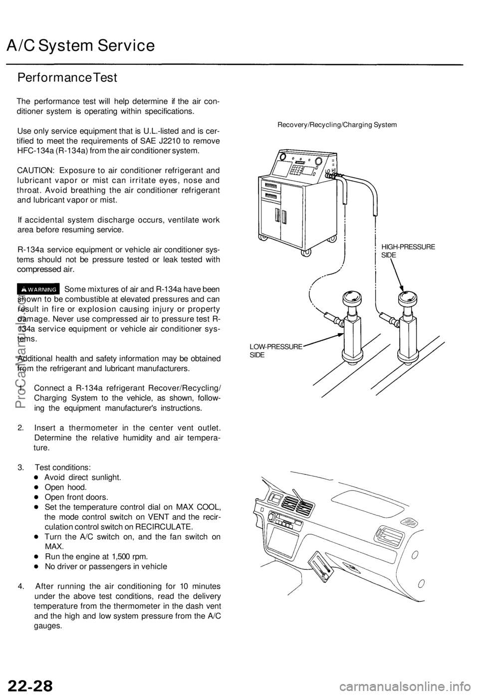
Connect a R-134a refrigerant Recover/Recycling/
Charging System to the vehicle, as shown, follow-
ing the equipment manufacturer's instructions.
Insert a thermometer in the center vent outlet.
Determine the relative humidity and air tempera-
ture.
Recovery/Recycling/Charging System
HIGH-PRESSURE
SIDE
LOW-PRESSURE
SIDE
3. Test conditions:
Avoid direct sunlight.
Open hood.
Open front doors.
Set the temperature control dial on MAX COOL,
the mode control switch on VENT and the recir-
culation control switch on RECIRCULATE.
Turn the A/C switch on, and the fan switch on
MAX.
Run the engine at 1,500 rpm.
No driver or passengers in vehicle
4. After running the air conditioning for 10 minutes
under the above test conditions, read the delivery
temperature from the thermometer in the dash vent
and the high and low system pressure from the A/C
gauges.ProCarManuals.com
Page 572 of 1771
A/C System Service
Charging
Use only service equipment that is U.L.-listed and is cer-
tified to meet the requirements of SAE J2210 to remove
HFC-134a (R-134a) from the air conditioner system.
CAUTION: Exposure to air conditioner refrigerant and
lubricant vapor or mist can irritate eyes, nose and throat.
Avoid breathing the air conditioner refrigerant and lubri-
cant vapor or mist.
If accidental system discharge occurs, ventilate work
area before resuming service. Additional health and
safety information may be obtained from the refrigerant
and lubricant manufacturers.
Refrigerant capacity: 750 g (26.5 oz)
CAUTION: Do not overcharge the system; the compressor
will be damaged.
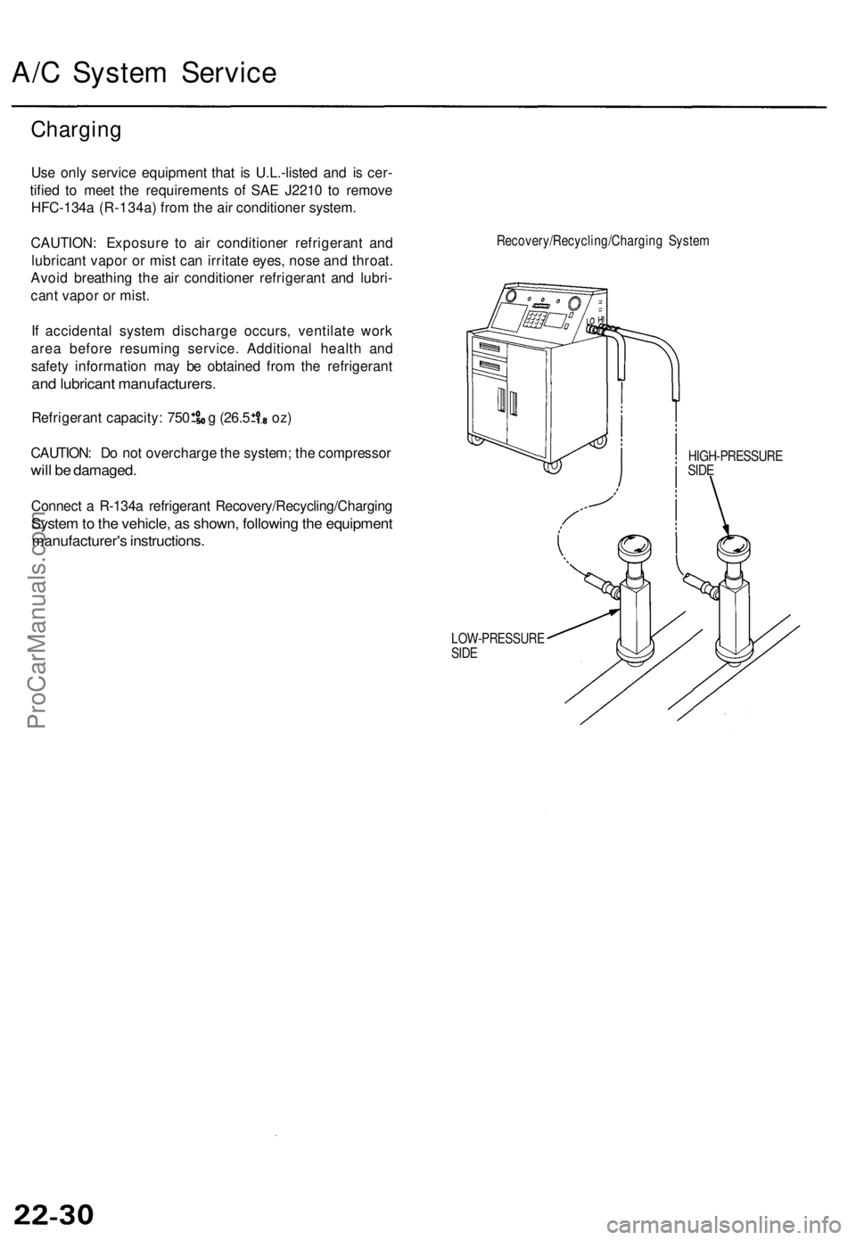
Connect a R-134a refrigerant Recovery/Recycling/Charging
System to the vehicle, as shown, following the equipment
manufacturer's instructions.
Recovery/Recycling/Charging System
HIGH-PRESSURE
SIDE
LOW-PRESSURE
SIDEProCarManuals.com
Page 601 of 1771
Charging Syste m
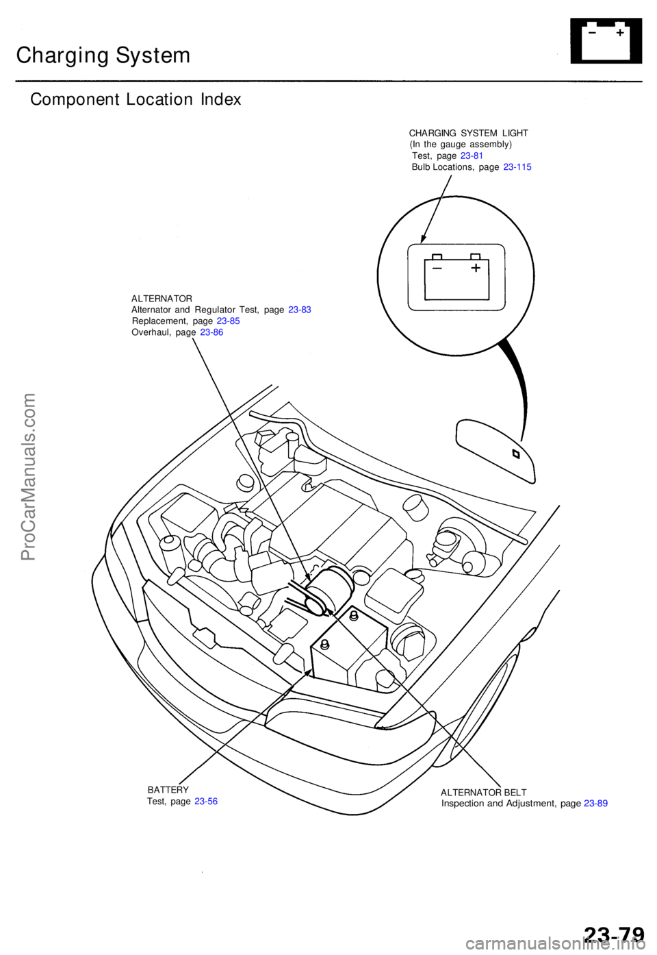
Componen t Locatio n Inde x
CHARGIN G SYSTE M LIGH T
(I n th e gaug e assembly )
ALTERNATO RAlternator an d Regulato r Test , pag e 23-8 3
Replacement , pag e 23-8 5
Overhaul , pag e 23-8 6
ALTERNATOR BEL T
Inspectio n an d Adjustment , pag e 23-8 9
BATTER YTest, pag e 23-5 6 Test
, pag e 23-8 1
Bulb Locations , pag e 23- 115
ProCarManuals.com