Page 1530 of 1771
Condenser
Replacemen t
1. Recove r th e refrigeran t wit h a Recovery/Recycling /
Charging Syste m (se e pag e 22-71 ).
2 . Remov e th e fron t grill e (se e sectio n 20 ).
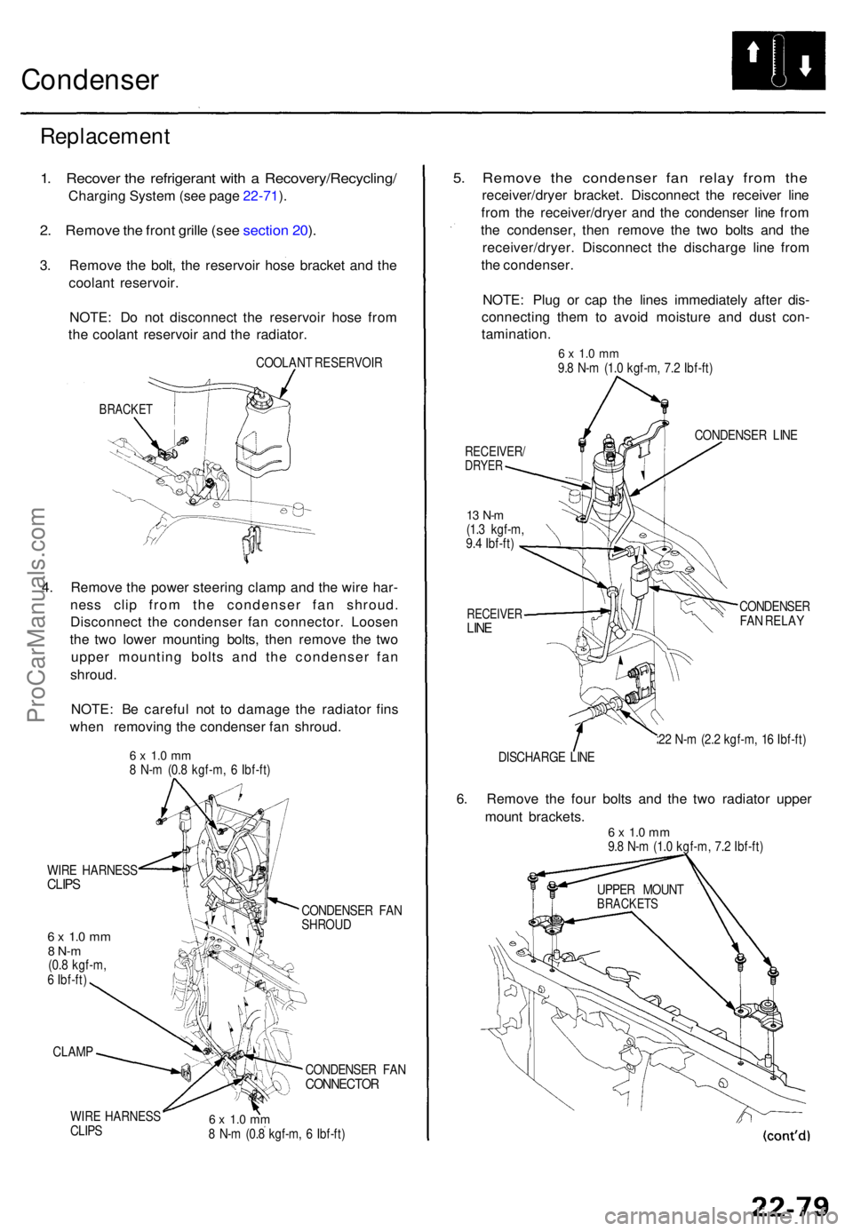
3 . Remov e th e bolt , th e reservoi r hos e bracke t an d th e
coolan t reservoir .
NOTE : D o no t disconnec t th e reservoi r hos e fro m
th e coolan t reservoi r an d th e radiator .
COOLAN T RESERVOI R
BRACKET
4. Remov e th e powe r steerin g clam p an d th e wir e har -
nes s cli p fro m th e condense r fa n shroud .
Disconnec t th e condense r fa n connector . Loose n
th e tw o lowe r mountin g bolts , the n remov e th e tw o
uppe r mountin g bolt s an d th e condense r fa n
shroud .
NOTE : B e carefu l no t t o damag e th e radiato r fin s
whe n removin g th e condense r fa n shroud .
6 x 1. 0 m m8 N- m (0. 8 kgf-m , 6 Ibf-ft )
WIR E HARNES S
CLIPS
6 x 1. 0 m m8 N- m(0.8 kgf-m ,
6 Ibf-ft )
CLAM P
WIR E HARNES S
CLIP S CONDENSE
R FA N
SHROU D
CONDENSE R FA N
CONNECTO R
6 x 1. 0 m m8 N- m (0. 8 kgf-m , 6 Ibf-ft )
5. Remov e th e condense r fa n rela y fro m th e
receiver/drye r bracket . Disconnec t th e receive r lin e
fro m th e receiver/drye r an d th e condense r lin e fro m
th e condenser , the n remov e th e tw o bolt s an d th e
receiver/dryer . Disconnec t th e discharg e lin e fro m
th e condenser .
NOTE : Plu g o r ca p th e line s immediatel y afte r dis -
connectin g the m to avoi d moistur e an d dus t con -
tamination .
6 x 1. 0 m m9.8 N- m (1. 0 kgf-m , 7. 2 Ibf-ft )
RECEIVER /DRYER
13 N- m(1.3 kgf-m ,
9. 4 Ibf-ft )
RECEIVE RLINE
CONDENSE R LIN E
CONDENSE R
FA N RELA Y
2 2 N- m (2. 2 kgf-m , 1 6 Ibf-ft )
DISCHARG E LIN E
6. Remov e th e fou r bolt s an d th e tw o radiato r uppe r
moun t brackets .
6 x 1. 0 m m9.8 N- m (1. 0 kgf-m , 7. 2 Ibf-ft )
UPPE R MOUN T
BRACKET S
ProCarManuals.com
Page 1532 of 1771
A/C System Service
Evacuation
Use only service equipment that is U.L.-listed and is cer-
tified to meet the requirements of SAE J2210 to remove
HFC-134a (R-134a) from the air conditioner system.
CAUTION: Exposure to air conditioner refrigerant and
lubricant vapor or mist can irritate eyes, nose and throat.
Avoid breathing the air conditioner refrigerant and lubri-
cant vapor or mist.
If accidental system discharge occurs, ventilate work
area before resuming service.
R-134a service equipment or vehicle air conditioner sys-
tems should not be pressure tested or leak tested with
compressed air.
Some mixtures of air and R-134a have been
shown to be combustible at elevated pressures and can
result in fire or explosion causing injury or property
damage. Never use compressed air to pressure test R-
134a service equipment or vehicle air conditioner sys-
tems.
Additional health and safety information may be obtained
from the refrigerant and lubricant manufacturers.
1. When an A/C System has been opened to the atmo-
sphere, such as during installation or repair, it must
be evacuated using a R-134a refrigerant Recovery/
Recycling/Charging System. (If the system has been
open for several days, the receiver/dryer should be
replaced, and the system should be evacuated for
several hours.)
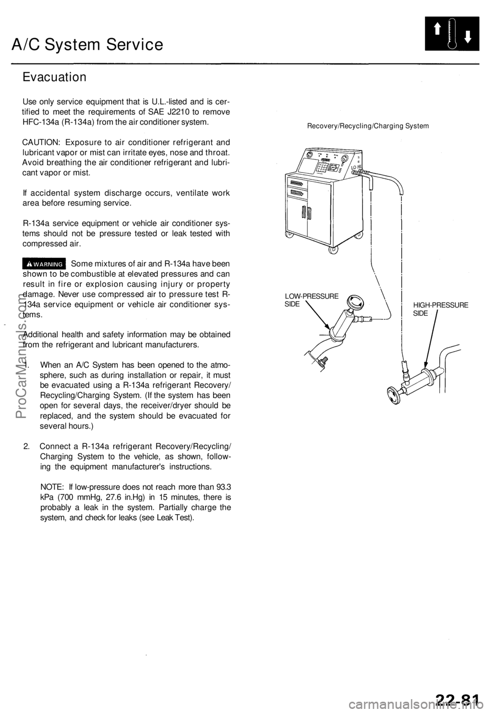
2. Connect a R-134a refrigerant Recovery/Recycling/
Charging System to the vehicle, as shown, follow-
ing the equipment manufacturer's instructions.
NOTE: If low-pressure does not reach more than 93.3
kPa (700 mmHg, 27.6 in.Hg) in 15 minutes, there is
probably a leak in the system. Partially charge the
system, and check for leaks (see Leak Test).
Recovery/Recycling/Charging System
HIGH-PRESSURE
SIDE
LOW-PRESSURE
SIDEProCarManuals.com
Page 1545 of 1771
Battery
Test
Battery fluid (electrolyte) contains sulfuric acid. It may cause severe burns if it gets on your skin or in your eyes. Wear
protective clothing and a face shield.
— If electrolyte gets on your skin or clothes, rinse it off with water immediately.
— If electrolyte gets in your eyes, flush it out by splashing water in your eyes for at least 15 minutes; call a physician
immediately.
A battery gives off hydrogen gas. If ignited, the hydrogen will explode and could crack the battery case and splatter
acid on you. Keep sparks, flames, and cigarettes away from the battery.
Overcharging will raise the temperature of the electrolyte. This may force electrolyte to spray out of the battery vents.
Follow the charger manufacturer's instructions, and charge the battery at a proper rate.
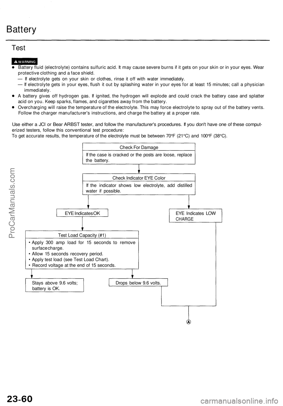
Use either a JCI or Bear ARBST tester, and follow the manufacturer's procedures. If you don't have one of these comput-
erized testers, follow this conventional test procedure:
To get accurate results, the temperature of the electrolyte must be between 70°F (21°C) and 100°F (38°C).
Check For Damage
If the case is cracked or the posts are loose, replace
the battery.
Check Indicator EYE Color
If the indicator shows low electrolyte, add distilled
water if possible.
EYE Indicates OK
EYE Indicates LOW
CHARGE
Test Load Capacity (#1)
Apply 300 amp load for 15 seconds to remove
surface charge.
Allow 15 seconds recovery period.
Apply test load (see Test Load Chart).
Record voltage at the end of 15 seconds.
Stays above 9.6 volts;
battery is OK.
Drops below 9.6 volts.ProCarManuals.com
Page 1577 of 1771
Charging Syste m
Componen t Locatio n Inde x
CHARGIN G SYSTE M LIGH T
(I n th e gaug e assembly )
Test , pag e 23-9 6
Bul b Locations , pag e 23-11 5
BATTER YTest, pag e 23-6 0
ALTERNATO RAlternator an d Regulato r Test , pag e 23-9 8
Replacement , pag e 23-10 0
Overhaul , pag e 23-10 1 ALTERNATO
R BEL T
Inspectio n an d Adjustment , pag e 23-10 4
ProCarManuals.com
Page 1578 of 1771
Charging System
Description
To improve fuel economy, the alternator control system within the ECM changes the voltage generated at the alternator in
accordance with driving conditions.
Throttle position (TP) sensor
Engine coolant temperature
(ECT) sensor
Intake air temperature (IAT)
sensor
TDC/CKP/CYP sensor
Vehicle speed sensor (VSS)
ELD
Air conditioning signal
ECM
Alternator
STARTER SWITCH ON
Generated voltage decreases from 14.0 V to 12.5 V
AND
ELECTRICAL LOAD below 15 A
and
VEHICLE SPEED between 9 mph (15 km/h) and
44 mph (70
km/h)
and
ENGINE SPEED between 1,100 rpm and 3,000 rpm
and
ENGINE COOLANT TEMPERATURE above 176°F
(80°C)
and
A/C SWITCH OFF
and
INTAKE AIR TEMPERATURE above 65°F (18°C)
AND
FUEL CUT-OFF CON-
TROL function is not
engaged.ProCarManuals.com
Page 1579 of 1771

Charging Syste m
Troubleshootin g
If th e chargin g syste m ligh t i s on , o r th e batter y is dea d o r low , tes t th e followin g item s in th e orde r liste d below .
1. Batter y (se e pag e 23-60 )
2. Chargin g Syste m Ligh t
3. Alternator/Regulato r
Check th e No . 4 (1 5 A)*1 o r (2 0A)*2 fus e i n th e under-das h fuse /
rela y box .
I s th e fus e OK ?
Chec k fo r a n ope n in th e L circuit :
1 . Disconnec t th e 4 P connecto r
from th e alternator .2. Groun d th e No . 4*1 o r No . 3*2
termina l o f th e 4 P connector .3. Tur n th e ignitio n switc h O N(II).
Doe s th e chargin g syste mlight com e on ?
4. Disconnec t th e No . 4*1 o r No .
3*2 termina l o f th e 4 P connec -tor fro m th e ground .
Does th e chargin g syste m
ligh t g o off ?
Doe s th e chargin g syste m
ligh t sta y off ?
(T o page 23-97) Replac
e th e fuse .
Chec k fo r a blow n chargin g sys -
te m ligh t bulb . I f th e bul b i s OK ,
repai r th e ope n i n th e WHT/BL U
wire .
Th e chargin g syste m ligh t circui tis OK .
Turn th e ignitio n switc h OFF , an d
repai r th e shor t t o groun d i n th e
WHT/BL U wire .
ALTERNATO R 4 P CONNECTO R
'95 - 9 6 model s '9 7 - 9 8 model s
*1 : '9 5 -9 6 model s
*2 : '9 7 - 9 8 model s WIR
E SID E O F FEMAL E TERMINAL S
ALTERNATO R 4 P CONNECTO R
'95 - 9 6 model s '9 7 - 9 8 model s
WIR E SID E O F FEMAL E TERMINAL S
Chec
k fo r a shor t t o bod y groun d
i n th e L circuit :
1. Tur n th e ignitio n switc h OFF .2. Disconnec t th e AB S contro l uni t
(C447)*1 an d integrate d contro l
uni t (C401) , a s applicable .
3. Tur n th e ignitio n switc h O N(II) .
ProCarManuals.com
Page 1581 of 1771
Charging Syste m
Troubleshootin g (cont'd )
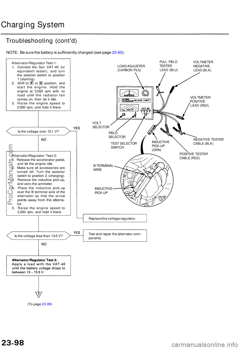
NOTE: B e sur e th e batter y is sufficientl y charge d (se e pag e 23-60 ).
Alternator/Regulato r Test-1 :
1 . Connec t th e Su n VAT-4 0 (o r
equivalen t tester) , an d tur n
th e selecto r switc h t o positio n
1 (starting) .
2. Shif t t o o r position , an d
star t th e engine . Hol d th e
engin e a t 3,00 0 rp m wit h n o
loa d unti l th e radiato r fa ncome s on , the n le t i t idle .
3 . Rais e th e engin e spee d t o
2,00 0 rpm , an d hol d i t there .
I s th e voltag e ove r 15. 1 V ?
I s th e voltag e les s tha n 13. 5 V ? LOA
D ADJUSTE R
(CARBON PILE )
FULL FIEL DTESTE RLEAD (BLU )
VOLTMETE RNEGATIVELEAD (BLK )
VOLTSELECTO R
FIELDSELECTO R
B TERMINA LWIRE
INDUCTIV EPICK-UP
VOLTMETE RPOSITIVELEAD (RED )
NEGATIV E TESTE RCABLE (BLK )
POSITIV E TESTE RCABLE (RED )
Replac e th e voltag e regulator .
Tes t an d repai r th e alternato r com -
ponents .
(T o page 23-99) INDUCTIV
E
PICK-UP(GRN)
TEST SELECTO RSWITCH
Alternator/Regulato r Test-2 :
1 . Releas e th e accelerato r pedal ,
an d le t th e engin e idle .
2 . Mak e sur e al l accessorie s ar e
turne d off . Tur n th e selecto r
switc h t o positio n 2 (charging) .
3 . Remov e th e inductiv e pick-up ,
an d zer o th e ammeter .
4 . Plac e th e inductiv e pick-u p
ove r th e B termina l wire of th e
alternato r s o tha t th e arro w
points awa y fro m th e alterna -tor.5. Rais e th e engin e spee d t o
2,00 0 rpm , an d hol d i t there .
ProCarManuals.com
Page 1583 of 1771
Charging Syste m
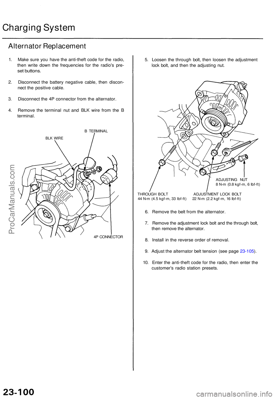
Alternato r Replacemen t
1. Mak e sur e yo u hav e th e anti-thef t cod e fo r th e radio ,
the n writ e dow n th e frequencie s fo r th e radio' s pre -
set buttons .
2. Disconnec t th e batter y negativ e cable , the n discon -
nec t th e positiv e cable .
3 . Disconnec t th e 4 P connecto r fro m th e alternator .
4 . Remov e th e termina l nu t an d BL K wir e fro m th e B
terminal .
B TERMINA L
BLK WIR E
4P CONNECTO R
5. Loose n th e throug h bolt , the n loose n th e adjustmen t
loc k bolt , an d the n th e adjustin g nut .
ADJUSTIN G NU T
8 N- m (0. 8 kgf-m , 6 Ibf-ft )
THROUG H BOL T ADJUSTMEN T LOC K BOL T
4 4 N- m (4. 5 kgf-m , 3 3 Ibf-ft ) 2 2 N- m (2. 2 kgf-m , 1 6 Ibf-ft )
6. Remov e th e bel t fro m th e alternator .
7 . Remov e th e adjustmen t loc k bol t an d th e throug h bolt ,
the n remov e th e alternator .
8 . Instal l i n th e revers e orde r o f removal .
9 . Adjus t th e alternato r bel t tensio n (se e pag e 23-105 ).
10 . Ente r th e anti-thef t cod e fo r th e radio , the n ente r th e
customer' s radi o statio n presets .
ProCarManuals.com