1995 ACURA TL cooling
[x] Cancel search: coolingPage 200 of 1771
PGM-FI System
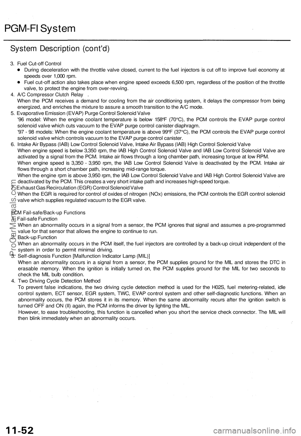
System Description (cont'd)
3. Fuel Cut-off Control
During deceleration with the throttle valve closed, current to the fuel injectors is cut off to improve fuel economy at
speeds over 1,000 rpm.
Fuel cut-off action also takes place when engine speed exceeds 6,500 rpm, regardless of the position of the throttle
valve, to protect the engine from over-revving.
4. A/C Compressor Clutch Relay .
When the PCM receives a demand for cooling from the air conditioning system, it delays the compressor from being
energized, and enriches the mixture to assure a smooth transition to the A/C mode.
5. Evaporative Emission (EVAP) Purge Control Solenoid Valve
'96 model: When the engine coolant temperature is below 158°F (70°C), the PCM controls the EVAP purge control
solenoid valve which cuts vacuum to the EVAP purge control canister diaphragm.
'97 - 98 models: When the engine coolant temperature is above 99°F (37°C), the PCM controls the EVAP purge control
solenoid valve which controls vacuum to the EVAP purge control canister.
6. Intake Air Bypass (IAB) Low Control Solenoid Valve, Intake Air Bypass (IAB) High Control Solenoid Valve
When engine speed is below 3,350 rpm, the IAB High Control Solenoid Valve and IAB Low Control Solenoid Valve are
activated by a signal from the PCM. Intake air flows through a long chamber path, increasing torque at low RPM.
When engine speed is 3,350 - 3,950 rpm, the IAB Low Control Solenoid Valve is deactivated by the PCM. Intake air
flows through a short chamber path, increasing mid-range torque.
When the engine rpm is above 3,950 rpm, the IAB Low Control Solenoid Valve and IAB High Control Solenoid Valve are
deactivated by the PCM. This creates a very short intake path and increases high-speed torque.
7. Exhaust Gas Recirculation (EGR) Control Solenoid Valve
When the EGR is required for control of oxides of nitrogen (NOx) emissions, the PCM controls the EGR control solenoid
valve which supplies regulated vacuum to the EGR valve.
ECM Fail-safe/Back-up Functions
1. Fail-safe Function
When an abnormality occurs in a signal from a sensor, the PCM ignores that signal and assumes a pre-programmed
value for that sensor that allows the engine to continue to run.
2. Back-up Function
When an abnormality occurs in the PCM itself, the fuel injectors are controlled by a back-up circuit independent of the
system in order to permit minimal driving.
3. Self-diagnosis Function [Malfunction Indicator Lamp (MIL)]
When an abnormality occurs in a signal from a sensor, the PCM supplies ground for the MIL and stores the DTC in
erasable memory. When the ignition is initially turned on, the PCM supplies ground for the MIL for two seconds to
check the MIL bulb condition.
4. Two Driving Cycle Detection Method
To prevent false indications, the two driving cycle detection method is used for the H02S, fuel metering-related, idle
control system, ECT sensor, EGR system, TWC, EVAP control system and other self-diagnostic functions. When an
abnormality occurs, the PCM stores it in its memory. When the same abnormality recurs after the ignition switch is
turned OFF and ON (II) again, the PCM informs the driver by lighting the MIL.
However, to ease troubleshooting, this function is cancelled when you short the service check connector. The MIL will
then blink immediately when an abnormality occurs.ProCarManuals.com
Page 327 of 1771
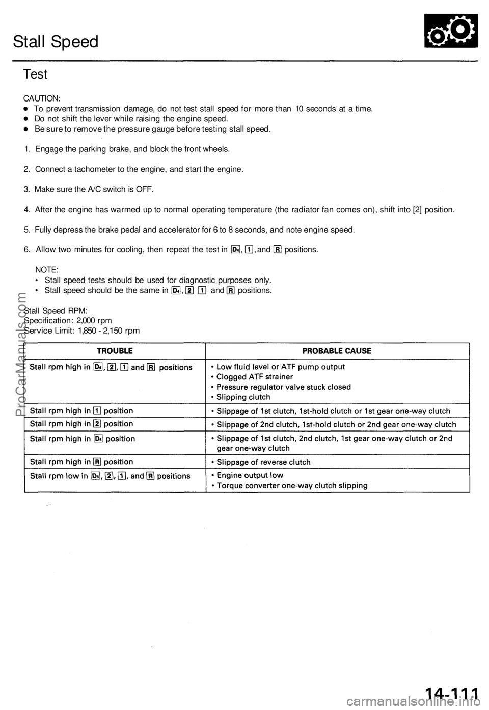
Stall Speed
Test
CAUTION:
To prevent transmission damage, do not test stall speed for more than 10 seconds at a time.
Do not shift the lever while raising the engine speed.
Be sure to remove the pressure gauge before testing stall speed.
1. Engage the parking brake, and block the front wheels.
2. Connect a tachometer to the engine, and start the engine.
3. Make sure the A/C switch is OFF.
4. After the engine has warmed up to normal operating temperature (the radiator fan comes on), shift into [2] position.
5. Fully depress the brake pedal and accelerator for 6 to 8 seconds, and note engine speed.
6. Allow two minutes for cooling, then repeat the test in , , and positions.
NOTE:
• Stall speed tests should be used for diagnostic purposes only.
• Stall speed should be the same in , and positions.
Stall Speed RPM:
Specification: 2,000 rpm
Service Limit: 1,850 - 2,150 rpmProCarManuals.com
Page 670 of 1771

EngineEngine Removal/Installation5±1 . . . . . . . . . . . . . . . . . . . . . . . .
Cylinder Head/Valve Train6±1 . . . . . . . . . . . . . . . . . . . . . . . . . . .
Engine Block7±1 . . . . . . . . . . . . . . . . . . . . . . . . . . . . . . . . . . . . . .
Engine Lubrication8±1 . . . . . . . . . . . . . . . . . . . . . . . . . . . . . . . . .
Intake Manifold/Exhaust System9±1 . . . . . . . . . . . . . . . . . . . .
Cooling10±1 . . . . . . . . . . . . . . . . . . . . . . . . . . . . . . . . . . . . . . . . . . . .
ProCarManuals.com
Page 671 of 1771
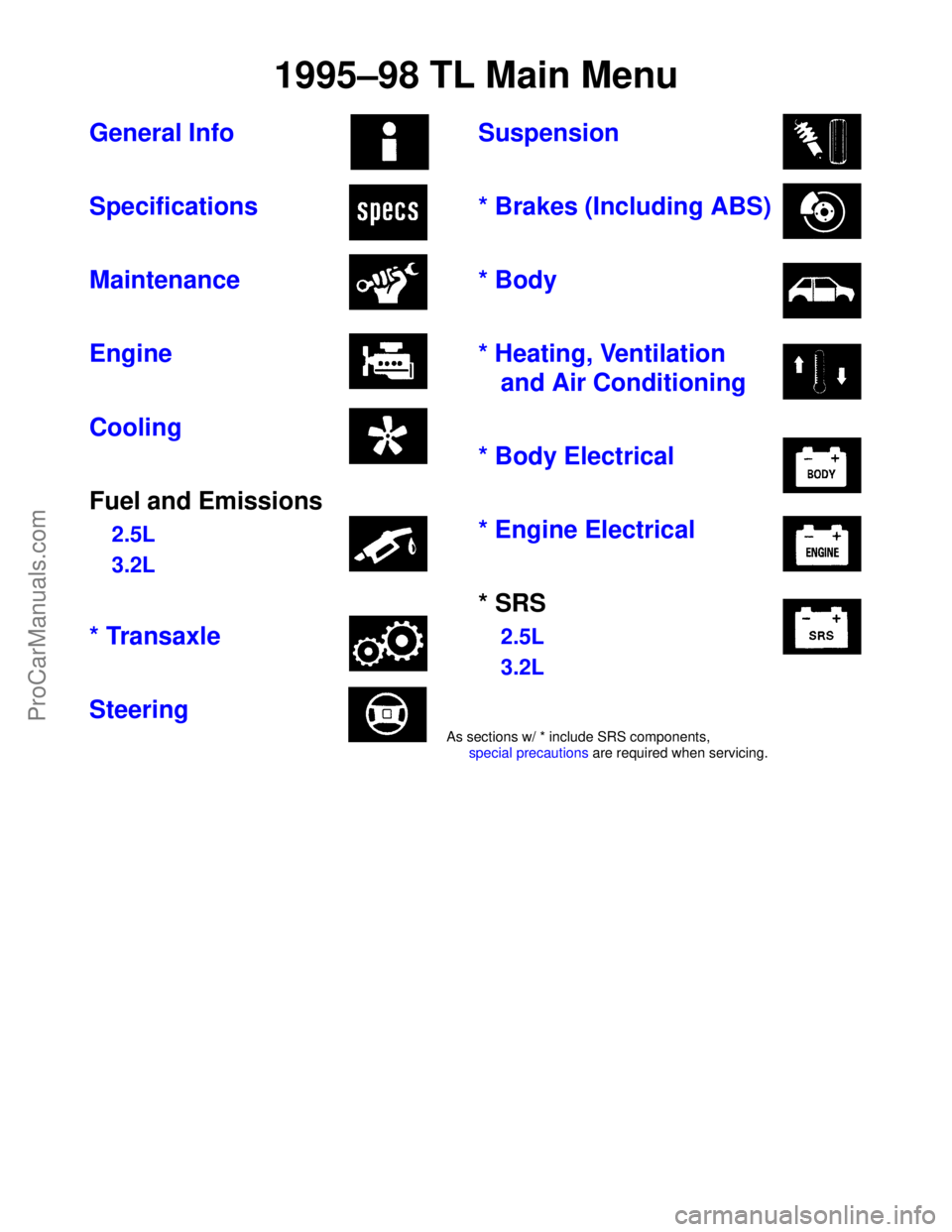
General Info
Specifications
Maintenance
Engine
Cooling
Fuel and Emissions
2.5L
3.2L
* Transaxle
SteeringSuspension
* Brakes (Including ABS)
* Body
* Heating, Ventilation
and Air Conditioning
* Body Electrical
* Engine Electrical
* SRS2.5L
3.2L
1995±98 TL Main Menu
As sections w/ * include SRS components, special precautions are required when servicing.
ProCarManuals.com
Page 995 of 1771
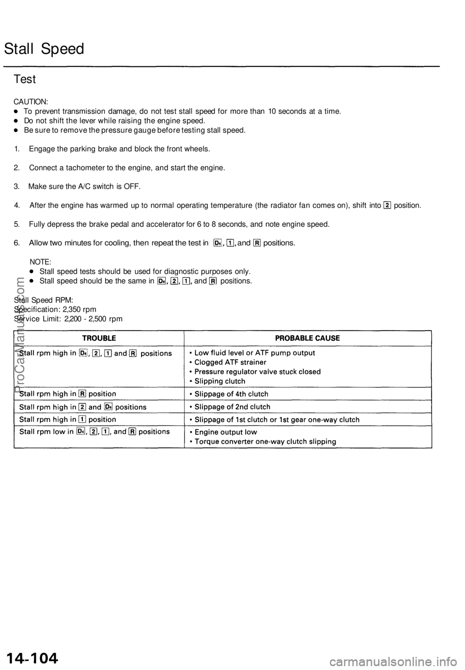
Stall Spee d
Test
CAUTION :
T o preven t transmissio n damage , d o no t tes t stal l spee d fo r mor e tha n 1 0 second s a t a time .
D o no t shif t th e leve r whil e raisin g th e engin e speed .
B e sur e to remov e th e pressur e gaug e befor e testin g stal l speed .
1 . Engag e th e parkin g brak e an d bloc k th e fron t wheels .
2 . Connec t a tachomete r t o th e engine , an d star t th e engine .
3 . Mak e sur e th e A/ C switc h is OFF .
4. Afte r th e engin e ha s warme d u p t o norma l operatin g temperatur e (th e radiato r fa n come s on) , shif t int o position .
5 . Full y depres s th e brak e peda l an d accelerato r fo r 6 to 8 seconds , an d not e engin e speed .
6. Allo w tw o minute s fo r cooling , the n repea t th e tes t i n and positions .
NOTE:
Stall spee d test s shoul d b e use d fo r diagnosti c purpose s only .
Stall spee d shoul d b e th e sam e in an d _ positions .
Stal l Spee d RPM :
Specification : 2,35 0 rp m
Servic e Limit : 2,20 0 - 2,50 0 rp m
ProCarManuals.com
Page 1494 of 1771
Troubleshooting
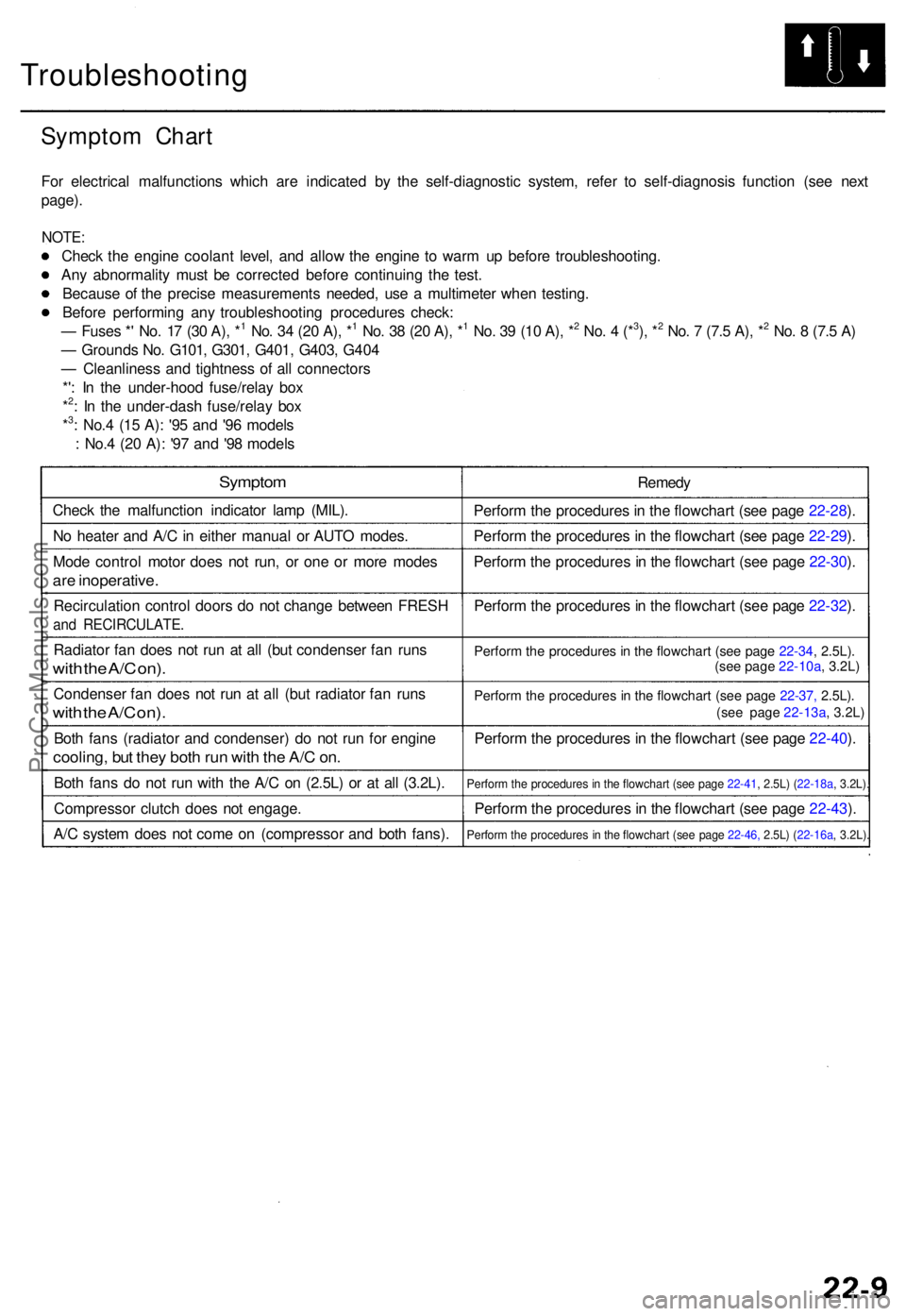
Symptom Char t
For electrica l malfunction s whic h ar e indicate d b y th e self-diagnosti c system , refe r t o self-diagnosi s functio n (se e nex t
page) .
NOTE :
Check th e engin e coolan t level , an d allo w th e engin e t o war m u p befor e troubleshooting .
An y abnormalit y mus t b e correcte d befor e continuin g th e test .
Becaus e o f th e precis e measurement s needed , us e a multimete r whe n testing .
Befor e performin g an y troubleshootin g procedure s check :
— Fuse s * ' No . 1 7 (3 0 A) , *
1 No . 3 4 (2 0 A) , *1 No . 3 8 (2 0 A) , *1 No . 3 9 (1 0 A) , *2 No . 4 (*3), *2 No . 7 (7. 5 A) , *2 No . 8 (7. 5 A )
— Ground s No . G101 , G301 , G401 , G403 , G40 4
— Cleanlines s an d tightnes s o f al l connector s
*' : I n th e under-hoo d fuse/rela y bo x
*
2: I n th e under-das h fuse/rela y bo x
*3: No. 4 (1 5 A) : '9 5 an d '9 6 model s
: No. 4 (2 0 A) : '9 7 an d '9 8 model s
Sympto m
Check th e malfunctio n indicato r lam p (MIL) .
N o heate r an d A/ C in eithe r manual or AUT O modes .
Mod e contro l moto r doe s no t run , o r on e o r mor e mode s
are inoperative .
Recirculatio n contro l door s d o no t chang e betwee n FRES H
and RECIRCULATE .
Radiator fa n doe s no t ru n a t al l (bu t condense r fa n run s
with th e A/ C on) .
Condense r fa n doe s no t ru n a t al l (bu t radiato r fa n run s
with th e A/ C on) .
Both fan s (radiato r an d condenser ) d o no t ru n fo r engin e
cooling , bu t the y bot h ru n wit h th e A/ C on .
Bot h fan s d o no t ru n wit h th e A/ C on (2.5L) or at all (3.2L) .
Compresso r clutc h doe s no t engage .
A/ C syste m doe s no t com e o n (compresso r an d bot h fans) . Remed
y
Perfor m th e procedure s in th e flowchar t (se e pag e 22-28 ).
Perfor m th e procedure s in th e flowchar t (se e pag e 22-29 ).
Perfor m th e procedure s in th e flowchar t (se e pag e 22-30 ).
Perfor m th e procedure s in th e flowchar t (se e pag e 22-32 ).
Perfor m th e procedure s in th e flowchar t (se e pag e 22-34 , 2.5L) .
Perfor m th e procedure s i n th e flowchar t (se e pag e 22-37, 2.5L).
Perfor m th e procedure s in th e flowchar t (se e pag e 22-40 ).
Perfor m th e procedure s in th e flowchar t (se e pag e 22-41 , 2.5L) ( 22-18a, 3.2L).
Perfor m th e procedure s in th e flowchar t (se e pag e 22-43 ).
Perfor m th e procedure s i n th e flowchar t (se e pag e 22-46, 2.5L) (22-16a , 3.2L).
(see page 22-10a, 3.2L)
(see page 22-13a , 3.2L)
ProCarManuals.com
Page 1576 of 1771
Ignition System
Spark Plug Inspection
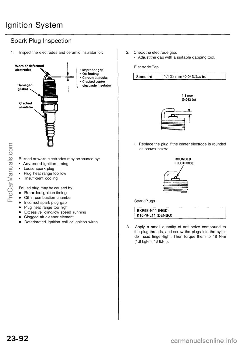
1. Inspect the electrodes and ceramic insulator for:
2. Check the electrode gap.
• Adjust the gap with a suitable gapping tool.
Electrode Gap
• Replace the plug if the center electrode is rounded
as shown below:
Burned or worn electrodes may be caused by:
• Advanced ignition timing
• Loose spark plug
• Plug heat range too low
• Insufficient cooling
Fouled plug may be caused by:
Retarded ignition timing
Oil in combustion chamber
Incorrect spark plug gap
Plug heat range too high
Excessive idling/low speed running
Clogged air cleaner element
Deteriorated ignition coil or ignition wires
3. Apply a small quantity of anti-seize compound to
the plug threads, and screw the plugs into the cylin-
der head finger-tight. Then torque them to 18 N-m
(1.8 kgf-m, 13 Ibf-ft).
Spark PlugsProCarManuals.com