1995 ACURA TL low oil pressure
[x] Cancel search: low oil pressurePage 64 of 1771

8. Disconnect the TCS throttle sensor connector and
TCS throttle actuator connector, then remove the
TCS control valve assembly.
Do not disconnect the breather pipe bypass hose.
TCS THROTTLE SENSOR
CONNECTOR
TCS THROTTLE
ACTUATOR CONNECTOR
TCS CONTROL VALVE
ASSEMBLY
9. Remove the oil pressure switch connector, engine
ground cable and engine wire harness cover.
6 x 1.0 mm
12 N-m (1.2 kgf-m, 8.7 Ibf-ft)
OIL PRESSURE
SWITCH CONNECTOR
ENGINE
GROUND
CABLE
ENGINE WIRE
HARNESS COVER
10. Remove the idler pulley bracket, dipstick and pipe.
6 x 1.0 mm
12 N-m (1.2 kgf-m,
8.7 Ibf-ft)
DIPSTICK/PIPE
8 x
1.25
mm
22 N-m (2.2 kgf-m, 16 Ibf-ft)
11. Remove the crankshaft pulley.
12. Remove the upper and lower covers.
NOTE: Do not use the upper and lower covers to
store removed items.
UPPER COVERS
Clean.
6 x 1.0 mm
12 N-m (1.2 kgf-m,
8.7 Ibf-ft)
LOWER COVER
Clean.
IDLER PULLEY
BRACKET
O-RING
Replace.ProCarManuals.com
Page 145 of 1771
Radiator
Cap Testing
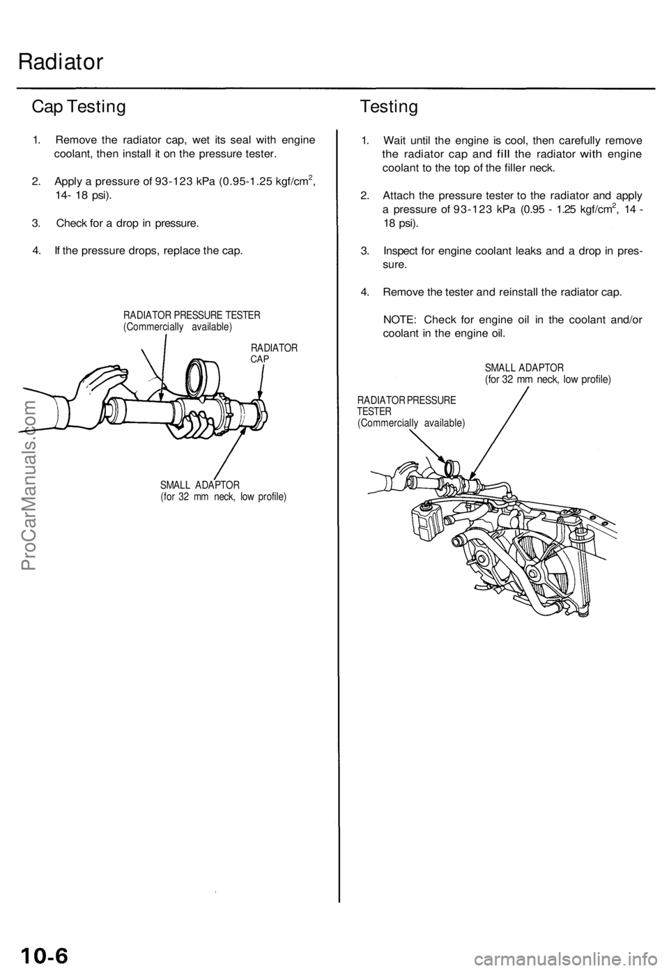
1. Remove the radiator cap, wet its seal with engine
coolant, then install it on the pressure tester.
2. Apply a pressure of 93-123 kPa (0.95-1.25 kgf/cm2,
14- 18
psi).
3. Check for a drop in pressure.
4. If the pressure drops, replace the cap.
RADIATOR PRESSURE TESTER
(Commercially available)
Testing
RADIATOR
CAP
SMALL ADAPTOR
(for 32 mm neck, low profile)
1. Wait until the engine is cool, then carefully remove
the
radiator
cap and
fill
the
radiator
with
engine
coolant to the top of the filler neck.
2. Attach the pressure tester to the radiator and apply
a pressure of 93-123 kPa (0.95 - 1.25 kgf/cm2, 14 -
18
psi).
3. Inspect for engine coolant leaks and a drop in pres-
sure.
4. Remove the tester and reinstall the radiator cap.
NOTE: Check for engine oil in the coolant and/or
coolant in the engine oil.
SMALL ADAPTOR
(for 32 mm neck, low profile)
RADIATOR PRESSURE
TESTER
(Commercially available)ProCarManuals.com
Page 201 of 1771
Powertrain Control Module (PCM)
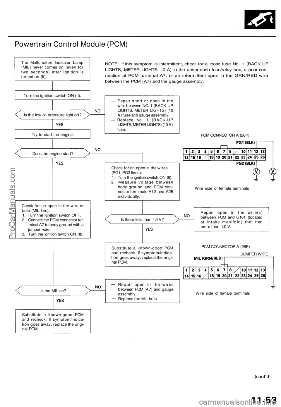
NOTE: If this symptom is intermittent, check for a loose fuse No. 1 (BACK UP
LIGHTS, METER LIGHTS, 10 A) in the under-dash fuse/relay box, a poor con-
nection at PCM terminal A7, or an intermittent open in the GRN/RED wire
between the PCM (A7) and the gauge assembly.
Is the low oil pressure light on?
Try to start the engine.
Does the engine start?
Check for an open in the wire or
bulb (MIL line):
1. Turn the ignition switch OFF.
2. Connect the PCM connector ter-
minal A7 to body ground with a
jumper wire.
3. Turn the ignition switch ON (II).
Is the MIL on?
Substitute a known-good PCM,
and recheck. If symptom/indica-
tion goes away, replace the origi-
nal
PCM.
— Repair short or open in the
wire between NO. 1 (BACK-UP
LIGHTS, METER LIGHTS) (10
A) fuse and gauge assembly.
— Replace No. 1 (BACK-UP
LIGHTS, METER LIGHTS) (10 A)
fuse.
PCM CONNECTOR A (26P)
Check for an open in the wires
(PG1, PG2 lines):
1. Turn the ignition switch ON (II).
2. Measure voltage between
body ground and PCM con-
nector terminals A12 and A25
individually.
Wire side of female terminals
Is there less than 1.0 V?
Repair open in the wire(s)
between PCM and G101 (located
at intake manifold) that had
more than 1.0 V.
PCM CONNECTOR A (26P)
JUMPER WIRE
Wire side of female terminals
Repair open in the wires
between PCM (A7) and gauge
assembly.
Replace the MIL bulb.
Substitute a known-good PCM
and recheck. If symptom/indica-
tion goes away, replace the origi-
nal
PCM.
Turn the ignition switch ON (II).
The Malfunction Indicator Lamp
(MIL) never comes on (even for
two seconds) after ignition is
turned on (II).ProCarManuals.com
Page 479 of 1771
Reassembly
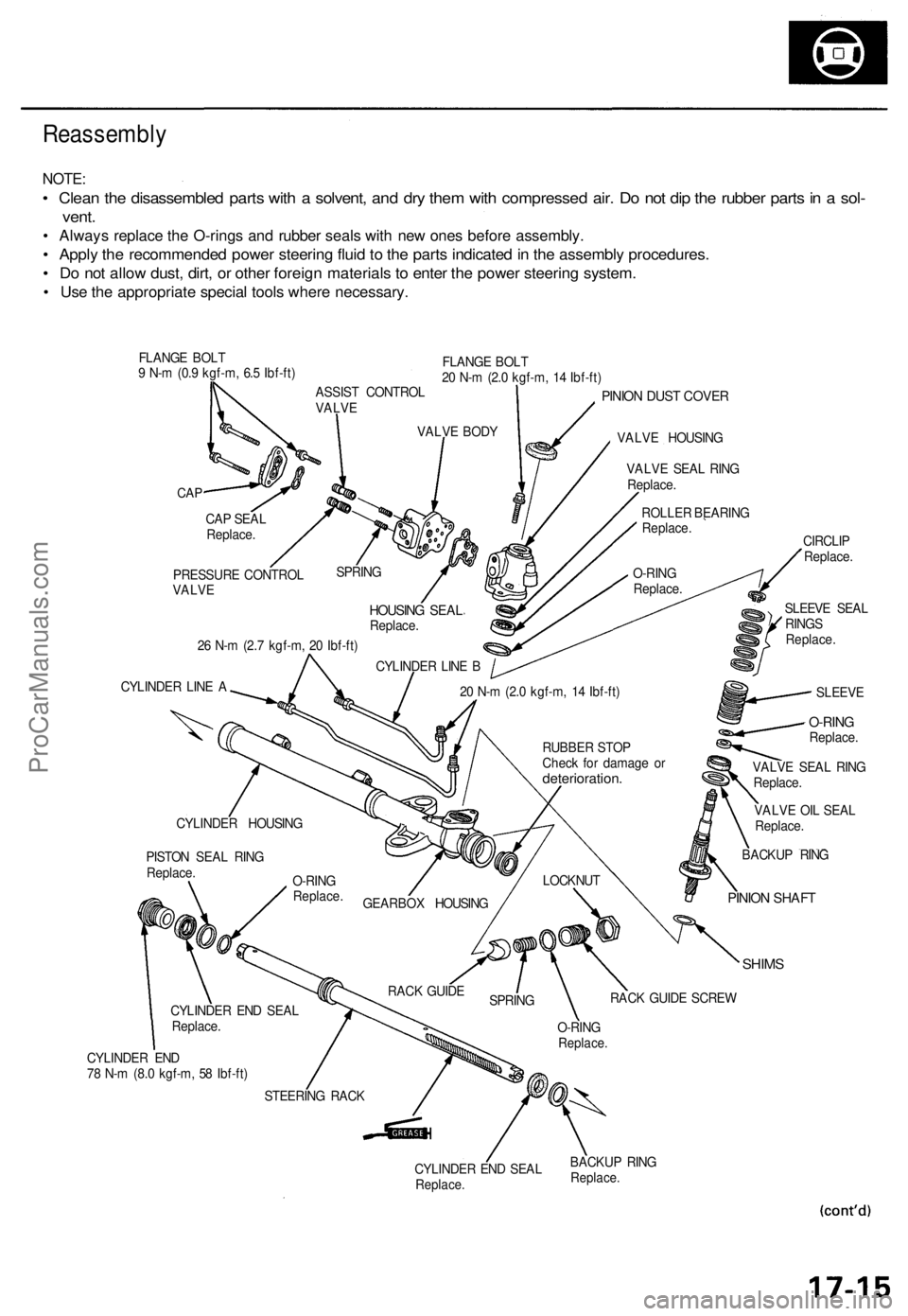
NOTE:
• Clean the disassembled parts with a solvent, and dry them with compressed air. Do not dip the rubber parts in a sol-
vent.
• Always replace the O-rings and rubber seals with new ones before assembly.
• Apply the recommended power steering fluid to the parts indicated in the assembly procedures.
• Do not allow dust, dirt, or other foreign materials to enter the power steering system.
• Use the appropriate special tools where necessary.
FLANGE BOLT
9 N-m (0.9 kgf-m, 6.5 Ibf-ft)
FLANGE BOLT
20 N-m (2.0 kgf-m, 14 Ibf-ft)
CAP
PINION DUST COVER
VALVE HOUSING
26 N-m (2.7 kgf-m, 20 Ibf-ft)
CYLINDER LINE A
VALVE OIL SEAL
Replace.
SHIMS
CYLINDER END
78 N-m (8.0 kgf-m, 58 Ibf-ft)
CYLINDER END SEAL
Replace.
BACKUP RING
Replace.
CAP SEAL
Replace.
PRESSURE CONTROL
VALVE
SPRING
HOUSING SEAL
Replace.
CYLINDER LINE B
VALVE BODY
ASSIST CONTROL
VALVE
VALVE SEAL RING
Replace.
ROLLER BEARING
Replace.
O-RING
Replace.
SLEEVE SEAL
RINGS
Replace.
CIRCLIP
Replace.
SLEEVE
20 N-m (2.0 kgf-m, 14 Ibf-ft)
BACKUP RING
PINION SHAFT
LOCKNUT
RACK GUIDE SCREW
O-RING
Replace.
SPRING
RACK GUIDE
STEERING RACK
CYLINDER END SEAL
Replace.
PISTON SEAL RING
Replace.
CYLINDER HOUSING
GEARBOX HOUSING
O-RING
Replace.
RUBBER STOP
Check for damage or
deterioration.
VALVE SEAL RING
Replace.
O-RING
Replace.ProCarManuals.com
Page 569 of 1771
A/C Service Tips and Precautions
The air
conditioner system uses
HFC-134a
(R-134a)
refrigerant
and
polyalkyleneglycol (PAG) refrigerant
oil*,
which
are not
compatible with CFC-12 (R-12) refrigerant and mineral oil. Do not use R-12 refrigerant or mineral oil in this system, and do
not attempt to use R-12 servicing equipment; damage to the air conditioner system or your servicing equipment will result.
*DENSO ND-OIL 8:
P/N 38897 - PR7 - A01AH: 120 (4 fl-oz, 4.2 Imp-oz)
P/N 38899 - PR7 - A01: 40 (1 1/3 fl-oz, 1.4 Imp-oz)
Use only service equipment that is U.L.-listed and is certified to meet the requirements of SAE J2210 to remove R-134a
from the air conditioner system.
CAUTION: Exposure to air conditioner refrigerant and lubricant vapor or mist can irritate eyes, nose and throat. Avoid
breathing the air conditioner refrigerant and lubricant vapor or mist.
If accidental system discharge occurs, ventilate work area before resuming service.
R-134a service equipment or vehicle air conditioner systems should not be pressure tested or leak tested with compressed
air.
Some mixtures of air and R-134a have been shown to be combustible at elevated pressures and can result
in tire or explosion causing injury or property damage. Never use compressed air to pressure test R-134a service equip-
ment or vehicle air conditioner systems.
Additional health and safety information may be obtained from the refrigerant and lubricant manufacturers.
1. Always disconnect the negative cable from the battery whenever replacing air conditioning parts.
2. Keep moisture and dust out of the system. When disconnecting any lines, plug or cap the fittings immediately; don't
remove the caps or plugs until just before you reconnect each line.
3. Before connecting any hose or line, apply a few drops of refrigerant oil to the O-ring.
4. When tightening or loosening a fitting, use a second wrench to support the matching fitting.
5. When discharging the system, use a R-134a refrigerant Recovery/Recycling/Charging System; don't release refriger-
ant into the atmosphere.
6. Add refrigerant oil after replacing the following parts:
NOTE:
To avoid contamination, do not return the oil to the container once dispensed, and never mix it with other refriger-
ant oils.
Immediately after using the oil, replace the cap on the container, and seal it to avoid moisture absorption.
Do not spill the refrigerant oil on the vehicle; it may damage the paint; if the refrigerant oil contacts the paint, wash
it off immediately.
Condenser ........................................ 25 (5/6 fl-oz, 0.9 Imp-oz)
Evaporator........................................ 50 (1 2/3 fl-oz, 1.8 Imp-oz)
Line or hose ...................................... 20 (2/3 fl-oz, 0.7 Imp-oz)
Receiver/Dryer
.................................
15
(1/2
fl-oz,
0.5
Imp-oz)
Leakage repair ................................. 25 (5/6 fl-oz, 0.9 Imp-oz)
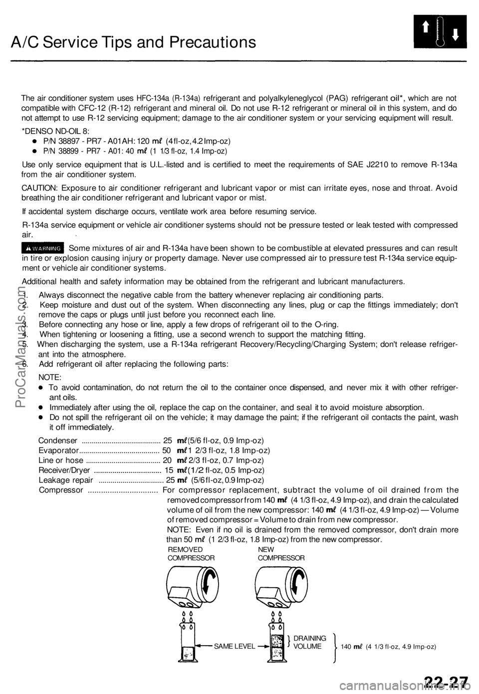
Compressor ................................ For compressor replacement, subtract the volume of oil drained from the
removed compressor from 140 (4 1/3 fl-oz, 4.9 Imp-oz), and drain the calculated
volume of oil from the new compressor: 140 (4 1/3 fl-oz, 4.9 Imp-oz) — Volume
of removed compressor = Volume to drain from new compressor.
NOTE: Even if no oil is drained from the removed compressor, don't drain more
than 50 (1 2/3 fl-oz, 1.8 Imp-oz) from the new compressor.
REMOVED NEW
COMPRESSOR COMPRESSOR
SAME LEVEL
140 (4 1/3 fl-oz, 4.9 Imp-oz)
DRAINING
VOLUMEProCarManuals.com
Page 879 of 1771
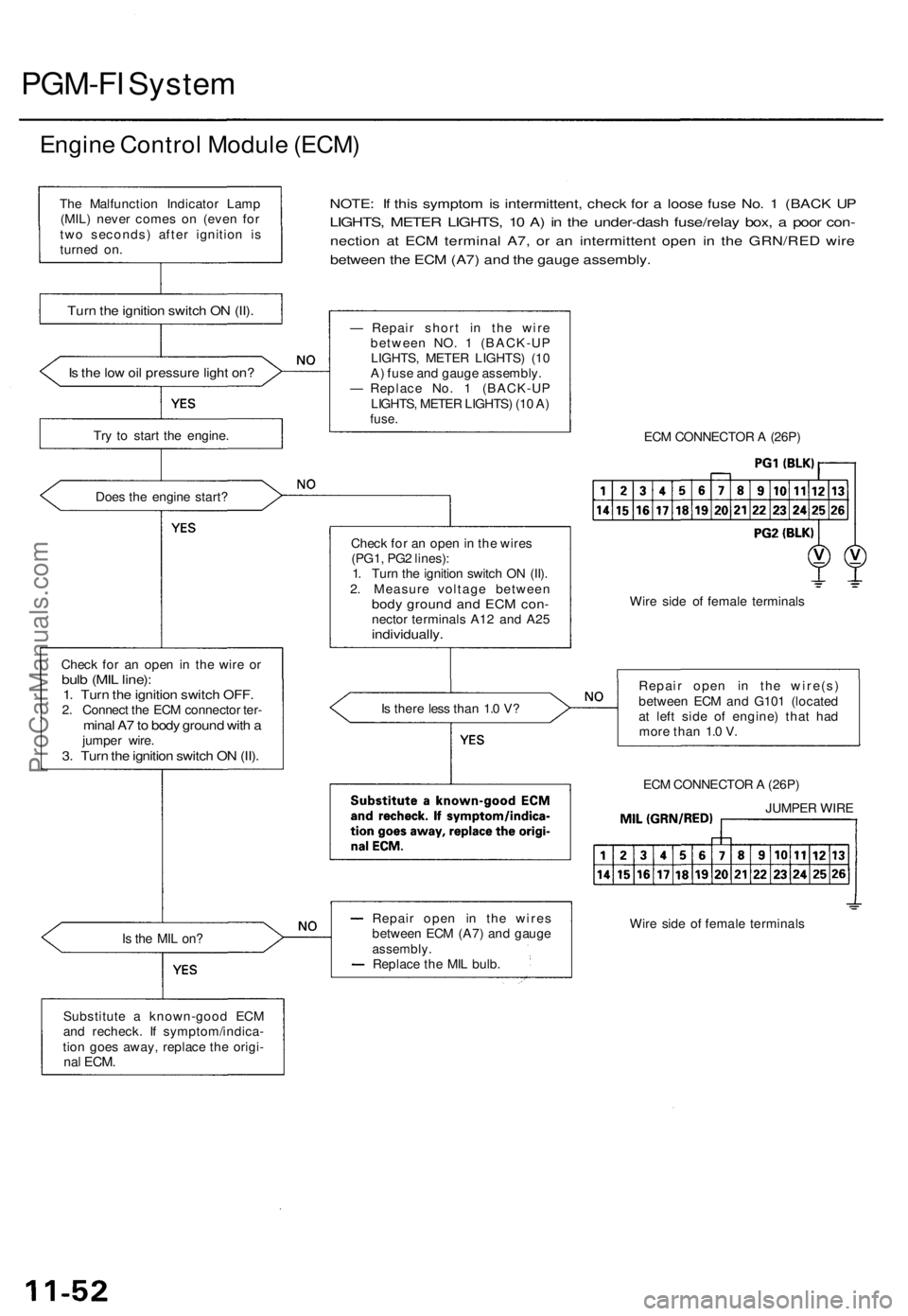
PGM-FI System
Engine Control Module (ECM)
Is the low oil pressure light on?
Try to start the engine.
Does the engine start?
Check for an open in the wire or
bulb (MIL line):
1. Turn the ignition switch OFF.
2. Connect the ECM connector ter-
minal A7 to body ground with a
jumper wire.
3. Turn the ignition switch ON (II).
NOTE: If this symptom is intermittent, check for a loose fuse No. 1 (BACK UP
LIGHTS, METER LIGHTS, 10 A) in the under-dash fuse/relay box, a poor con-
nection at ECM terminal A7, or an intermittent open in the GRN/RED wire
between the ECM (A7) and the gauge assembly.
Is the MIL on?
Substitute a known-good ECM
and recheck. If symptom/indica-
tion goes away, replace the origi-
nal
ECM.
— Repair short in the wire
between NO. 1 (BACK-UP
LIGHTS, METER LIGHTS) (10
A) fuse and gauge assembly.
— Replace No. 1 (BACK-UP
LIGHTS, METER LIGHTS) (10 A)
fuse.
Check for an open in the wires
(PG1, PG2 lines):
1. Turn the ignition switch ON (II).
2. Measure voltage between
body ground and ECM con-
nector terminals A12 and A25
individually.
Is there less than 1.0 V?
Repair open in the wires
between ECM (A7) and gauge
assembly.
Replace the MIL bulb.
ECM CONNECTOR A (26P)
Wire side of female terminals
Repair open in the wire(s)
between ECM and G101 (located
at left side of engine) that had
more than 1.0 V.
ECM CONNECTOR A (26P)
Wire side of female terminals
The Malfunction Indicator Lamp
(MIL) never comes on (even for
two seconds) after ignition is
turned on.
Turn the ignition switch ON (II).
JUMPER WIREProCarManuals.com
Page 1290 of 1771
Anti-lock Brake System (ABS)
Features/Construction (cont'd)
Wheel sensor:
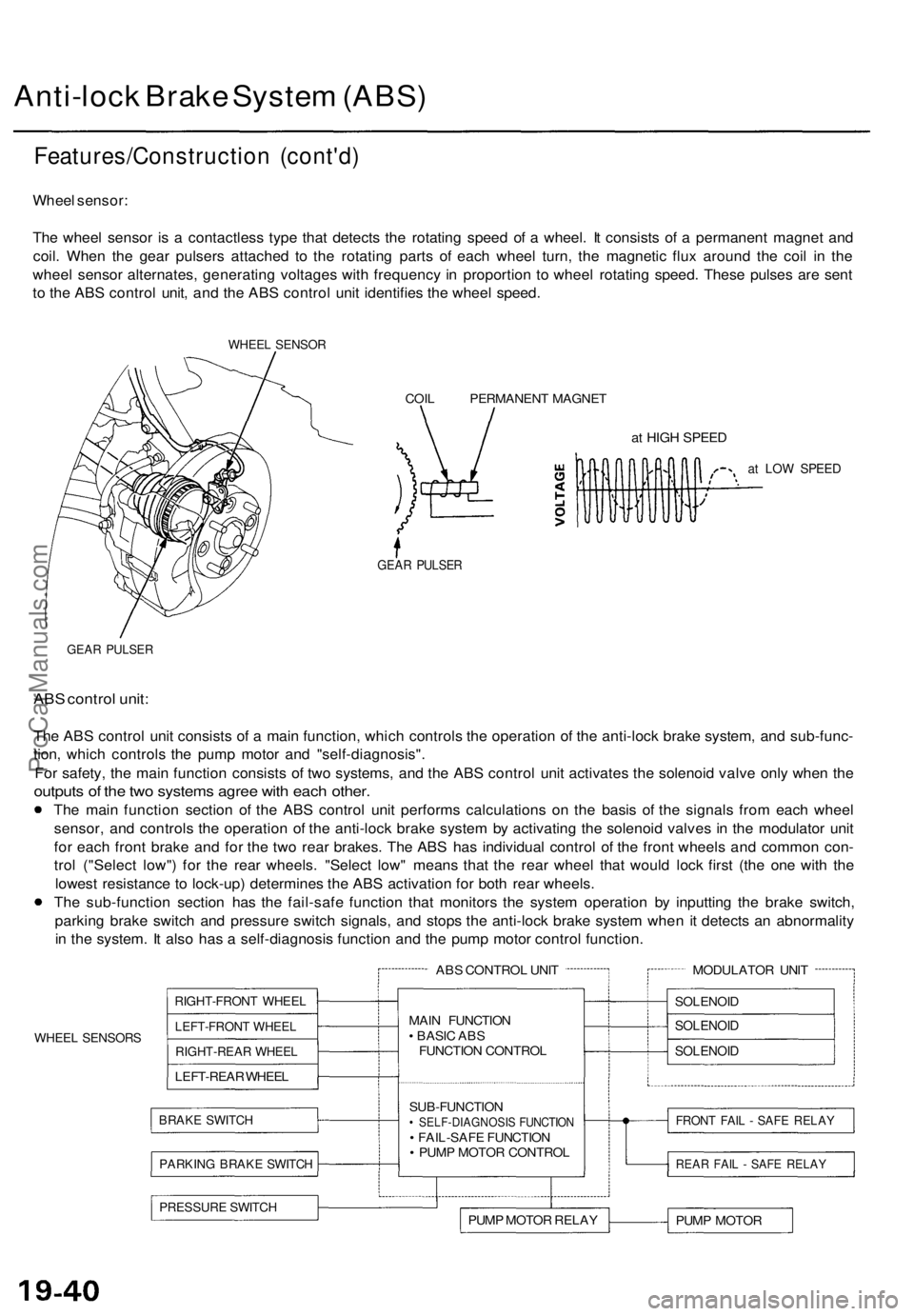
The wheel sensor is a contactless type that detects the rotating speed of a wheel. It consists of a permanent magnet and
coil. When the gear pulsers attached to the rotating parts of each wheel turn, the magnetic flux around the coil in the
wheel sensor alternates, generating voltages with frequency in proportion to wheel rotating speed. These pulses are sent
to the ABS control unit, and the ABS control unit identifies the wheel speed.
WHEEL SENSOR
COIL PERMANENT MAGNET
at HIGH SPEED
at LOW SPEED
GEAR PULSER
GEAR PULSER
ABS control unit:
The ABS control unit consists of a main function, which controls the operation of the anti-lock brake system, and sub-func-
tion, which controls the pump motor and "self-diagnosis".
For safety, the main function consists of two systems, and the ABS control unit activates the solenoid valve only when the
outputs of the two systems agree with each other.
The main function section of the ABS control unit performs calculations on the basis of the signals from each wheel
sensor, and controls the operation of the anti-lock brake system by activating the solenoid valves in the modulator unit
for each front brake and for the two rear brakes. The ABS has individual control of the front wheels and common con-
trol ("Select low") for the rear wheels. "Select low" means that the rear wheel that would lock first (the one with the
lowest resistance to lock-up) determines the ABS activation for both rear wheels.
The sub-function section has the fail-safe function that monitors the system operation by inputting the brake switch,
parking brake switch and pressure switch signals, and stops the anti-lock brake system when it detects an abnormality
in the system. It also has a self-diagnosis function and the pump motor control function.
WHEEL SENSORS
ABS CONTROL UNIT
RIGHT-FRONT WHEEL
LEFT-FRONT WHEEL
RIGHT-REAR WHEEL
LEFT-REAR WHEEL
BRAKE SWITCH
PARKING BRAKE SWITCH
MAIN FUNCTION
• BASIC ABS
FUNCTION CONTROL
SUB-FUNCTION
• SELF-DIAGNOSIS FUNCTION
• FAIL-SAFE FUNCTION
• PUMP MOTOR CONTROL
PRESSURE SWITCH
PUMP MOTOR RELAY
MODULATOR UNIT
SOLENOID
SOLENOID
SOLENOID
FRONT FAIL - SAFE RELAY
REAR FAIL - SAFE RELAY
PUMP MOTORProCarManuals.com
Page 1291 of 1771
Pump motor control:
The ABS control unit monitors the brake fluid pressure in the accumulator by the pressure switch ON/OFF signals. The
ABS control unit turns the pump on when the pressure in the accumulator drops, and stops the pump when the pressure
rises to the specified value.
If the pressure does not reach the specified value after the motor has operated continuously for a specified period, the
ABS control unit stops the motor and activates the ABS indicator light.
Self-diagnosis function:
The self-diagnosis function, provided in the sub-function of the ABS control unit, monitors the main system functions by
constantly transmitting the data between the two Central Processing Units (CPUs). When an abnormality is detected, the
ABS control unit turns the ABS indicator light on and stops the ABS, although the basic brake system continues to operate
normally.
When the ABS control unit detects an abnormality with the ABS and turns the ABS indicator light on, the diagnostic trou-
ble code (DTC), which shows the problem part or unit, is recorded in the control unit. The DTC can be read by the blinking
frequency of the ABS indicator light.
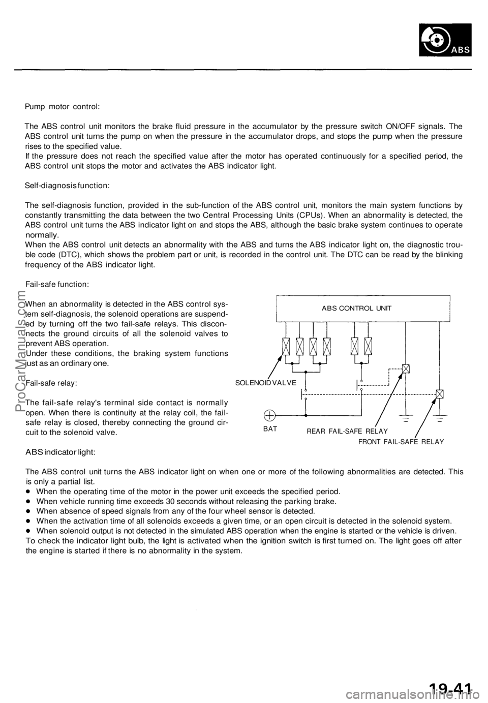
Fail-safe function:
When an abnormality is detected in the ABS control sys-
tem self-diagnosis, the solenoid operations are suspend-
ed by turning off the two fail-safe relays. This discon-
nects the ground circuits of all the solenoid valves to
prevent ABS operation.
Under these conditions, the braking system functions
just as an ordinary one.
Fail-safe relay:
The fail-safe relay's terminal side contact is normally
open. When there is continuity at the relay coil, the fail-
safe relay is closed, thereby connecting the ground cir-
cuit to the solenoid valve.
ABS indicator light:
SOLENOID VALVE
BAT
REAR FAIL-SAFE RELAY
FRONT FAIL-SAFE RELAY
The ABS control unit turns the ABS indicator light on when one or more of the following abnormalities are detected. This
is only a partial list.
When the operating time of the motor in the power unit exceeds the specified period.
When vehicle running time exceeds 30 seconds without releasing the parking brake.
When absence of speed signals from any of the four wheel sensor is detected.
When the activation time of all solenoids exceeds a given time, or an open circuit is detected in the solenoid system.
When solenoid output is not detected in the simulated ABS operation when the engine is started or the vehicle is driven.
To check the indicator light bulb, the light is activated when the ignition switch is first turned on. The light goes off after
the engine is started if there is no abnormality in the system.
ABS CONTROL UNITProCarManuals.com