Page 81 of 1771
Rocker Ar m Assembl y
Removal
NOTE:
Unscre w th e camshaf t holde r bolts , tw o turn s a t a
tim e i n a crisscros s pattern , t o preven t damagin g th e
valve s o r rocke r ar m assembly .
Whe n removin g th e rocke r ar m assembly , d o no t
remov e th e camshaf t holde r bolts . Th e bolt s wil l kee p
the camshaf t holders , th e spring s an d th e rocke r arm s
o n th e shafts .
CAMSHAF T HOLDE R BOLT S LOOSENIN G SEQUENCE :
Engin e No . 1300001~130926 2 (U.S.A.) , 1700001~170075 1 (Canada) :
6 m m BOLT S
8 m m BOLT S
Engine No . 1309263~ , 2300001~ , 3300001 ~ (U.S.A.) , 1700752~ , 270000 1 ~ ,
3700001 ~ (Canada) :
8 m m bolts :
NOTE : Refe r t o pag e 6-3 3 whe n installing .
ProCarManuals.com
Page 103 of 1771
Drive Plat e Connectin
g Ro d an dCrankshaf t
Replacemen t En
d Pla y
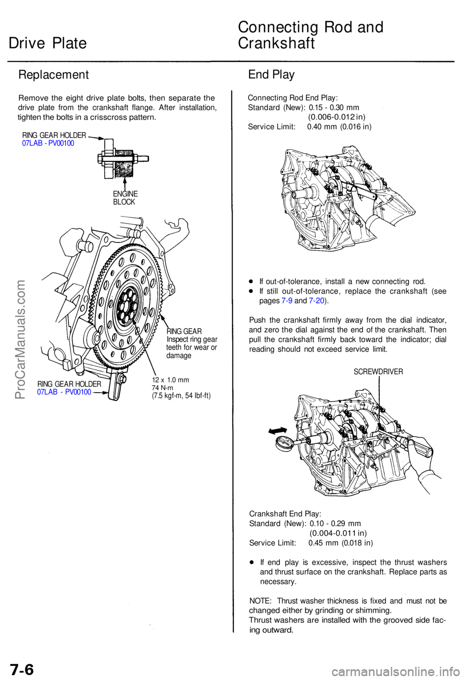
Remov e th e eigh t driv e plat e bolts , the n separat e th e
driv e plat e fro m th e crankshaf t flange . Afte r installation ,
tighten th e bolt s in a crisscros s pattern .
RING GEA R HOLDE R07LAB - PV0010 0
ENGINEBLOCK
RING GEA R HOLDE R07LAB - PV0010 0
RING GEA RInspec t rin g gea rteeth fo r wea r o rdamag e
12 x 1. 0 m m74 N- m(7.5 kgf-m , 5 4 Ibf-ft )
Connectin g Ro d En d Play :
Standar d (New) : 0.1 5 - 0.3 0 m m
(0.006-0.01 2 in )
Servic e Limit : 0.4 0 m m (0.01 6 in )
I f out-of-tolerance , instal l a ne w connectin g rod .
I f stil l out-of-tolerance , replac e th e crankshaf t (se e
page s 7- 9 an d 7-20 ).
Pus h th e crankshaf t firml y awa y fro m th e dia l indicator ,
an d zer o th e dia l agains t th e en d o f th e crankshaft . The n
pul l th e crankshaf t firml y bac k towar d th e indicator ; dia l
readin g shoul d no t excee d servic e limit .
SCREWDRIVE R
Crankshaft En d Play :
Standar d (New) : 0.1 0 - 0.2 9 m m
(0.004-0.01 1 in )
Servic e Limit : 0.4 5 m m (0.01 8 in )
I f en d pla y i s excessive , inspec t th e thrus t washer s
an d thrus t surfac e o n th e crankshaft . Replac e part s a s
necessary .
NOTE: Thrus t washe r thicknes s i s fixe d an d mus t no t b e
change d eithe r b y grindin g o r shimming .
Thrust washer s ar e installe d wit h th e groove d sid e fac -
ing outward .
ProCarManuals.com
Page 360 of 1771
1. Remove the eight 6 mm bolts and one 8 mm bolt
securing the regulator valve body, then remove the
regulator valve body.
2. Remove the stator shaft, stop shaft, and the regula-
tor separator plate.
3. Remove the three 6 mm bolts and two 8 mm bolts
securing the ATF pump body, then remove the ATF
pump body.
4. Remove the ATF pump driven gear shaft, ATF pump
gears, torque converter check valve, and spring.
5. Remove the four bolts securing the accumulator
cover, then remove the accumulator cover.
NOTE: The accumulator cover is spring loaded. To
prevent stripping the threads in the torque converter
housing, press down on the accumulator cover
while unscrewing the bolts in a crisscross pattern.
6. Remove the eight ATF feed pipes from the accumu-
lator body.
7. Remove the eight 6 mm bolts and seven 6 mm spe-
cial bolts securing the accumulator body, then
remove the accumulator body.
8. Remove the torque converter housing separator
plate with three dowel pins.ProCarManuals.com
Page 424 of 1771
Transmission
Installation
1. Flush the ATF cooler (see flushing procedure in the
'95 - '98 Acura 2.5TL Service Manual, 61SW504).
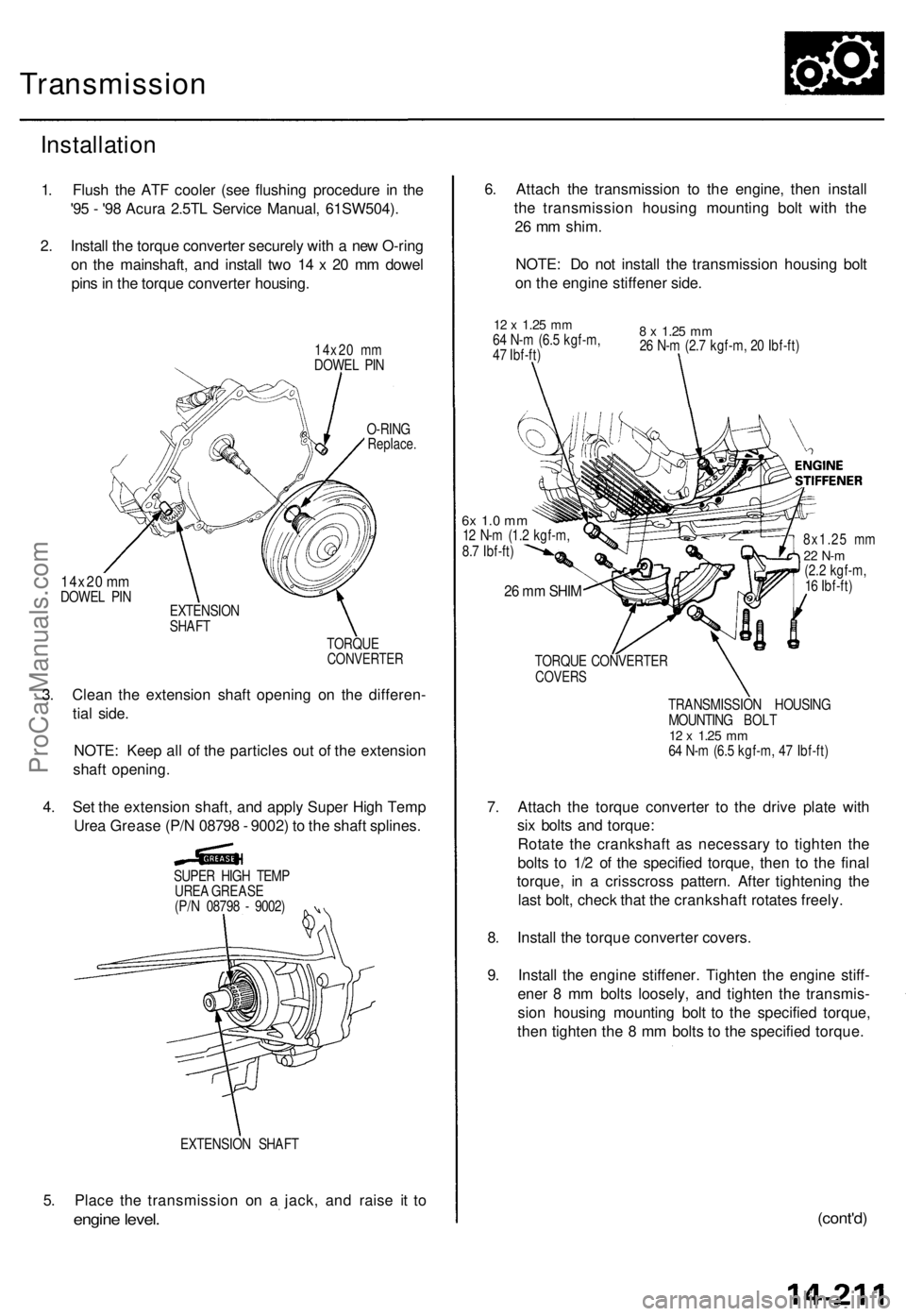
2. Install the torque converter securely with a new O-ring
on the mainshaft, and install two 14 x 20 mm dowel
pins in the torque converter housing.
14x20 mm
DOWEL PIN
14x20 mm
DOWEL PIN
O-RING
Replace.
EXTENSION
SHAFT
TORQUE
CONVERTER
3. Clean the extension shaft opening on the differen-
tial side.
NOTE: Keep all of the particles out of the extension
shaft opening.
4. Set the extension shaft, and apply Super High Temp
Urea Grease (P/N 08798 - 9002) to the shaft splines.
SUPER HIGH TEMP
UREA GREASE
(P/N 08798 - 9002)
EXTENSION SHAFT
5. Place the transmission on a jack, and raise it to
engine level.
6. Attach the transmission to the engine, then install
the transmission housing mounting bolt with the
26 mm shim.
NOTE: Do not install the transmission housing bolt
on the engine stiffener side.
12 x
1.25
mm
64 N-m (6.5 kgf-m,
47 Ibf-ft)
8 x
1.25
mm
26 N-m (2.7 kgf-m, 20 Ibf-ft)
6x 1.0 mm
12 N-m (1.2 kgf-m,
8.7 Ibf-ft)
26 mm SHIM
8x1.25 mm
22 N-m
(2.2 kgf-m,
16 Ibf-ft)
TORQUE CONVERTER
COVERS
TRANSMISSION HOUSING
MOUNTING BOLT
12 x
1.25
mm
64 N-m (6.5 kgf-m, 47 Ibf-ft)
7. Attach the torque converter to the drive plate with
six bolts and torque:
Rotate the crankshaft as necessary to tighten the
bolts to 1/2 of the specified torque, then to the final
torque, in a crisscross pattern. After tightening the
last bolt, check that the crankshaft rotates freely.
8. Install the torque converter covers.
9. Install the engine stiffener. Tighten the engine stiff-
ener 8 mm bolts loosely, and tighten the transmis-
sion housing mounting bolt to the specified torque,
then tighten the 8 mm bolts to the specified torque.
(cont'd)ProCarManuals.com
Page 438 of 1771
Differential Assembl y
Inspection
To establis h a startin g poin t befor e disassembly , inspec t
the following :
• Rin g gea r backlas h
• Tota l bearin g preloa d
• Gea r toot h contac t
NOTE:
• B e sur e th e differentia l i s a t roo m temperatur e befor e
inspecting .
• Recor d th e result s o f th e preliminar y inspections .
This informatio n wil l b e helpfu l during reassembly .
Ring gea r backlas h
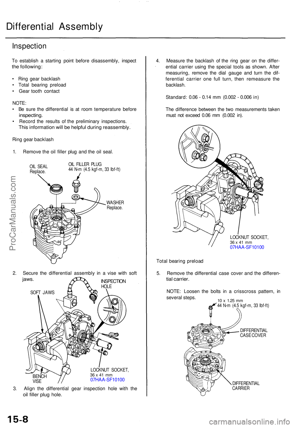
1 . Remov e th e oi l fille r plu g an d th e oi l seal .
OIL SEA L
Replace . OI
L FILLE R PLU G
4 4 N- m (4. 5 kgf-m , 3 3 Ibf-ft )
WASHE R
Replace .
BENCHVISE LOCKNU
T SOCKET ,
36 x 4 1 m m07HAA-SF1010 0
3. Alig n th e differentia l gea r inspectio n hol e wit h th e
oil fille r plu g hole .
4. Measur e th e backlas h o f th e rin g gea r o n th e differ -
entia l carrie r usin g th e specia l tool s a s shown . Afte r
measuring , remov e th e dia l gaug e an d tur n th e dif -
ferentia l carrie r on e ful l turn , the n remeasur e th e
backlash .
Standard : 0.0 6 - 0.1 4 m m (0.00 2 - 0.00 6 in )
Th e differenc e betwee n th e tw o measurement s take n
mus t no t excee d 0.0 6 m m (0.00 2 in) .
LOCKNU T SOCKET ,36 x 4 1 m m07HAA-SF1010 0
Total bearin g preloa d
5 . Remov e th e differentia l cas e cove r an d th e differen -
tial carrier .
NOTE: Loose n th e bolt s i n a crisscros s pattern , i n
severa l steps .
10 x 1.2 5 mm44 N- m (4. 5 kgf-m , 3 3 Ibf-ft )
DIFFERENTIA L
CAS E COVE R
DIFFERENTIA L
CARRIER
SOFT JAW S
INSPECTIO NHOLE
2. Secur e th e differentia l assembl y i n a vis e wit h sof t
jaws .
ProCarManuals.com
Page 439 of 1771
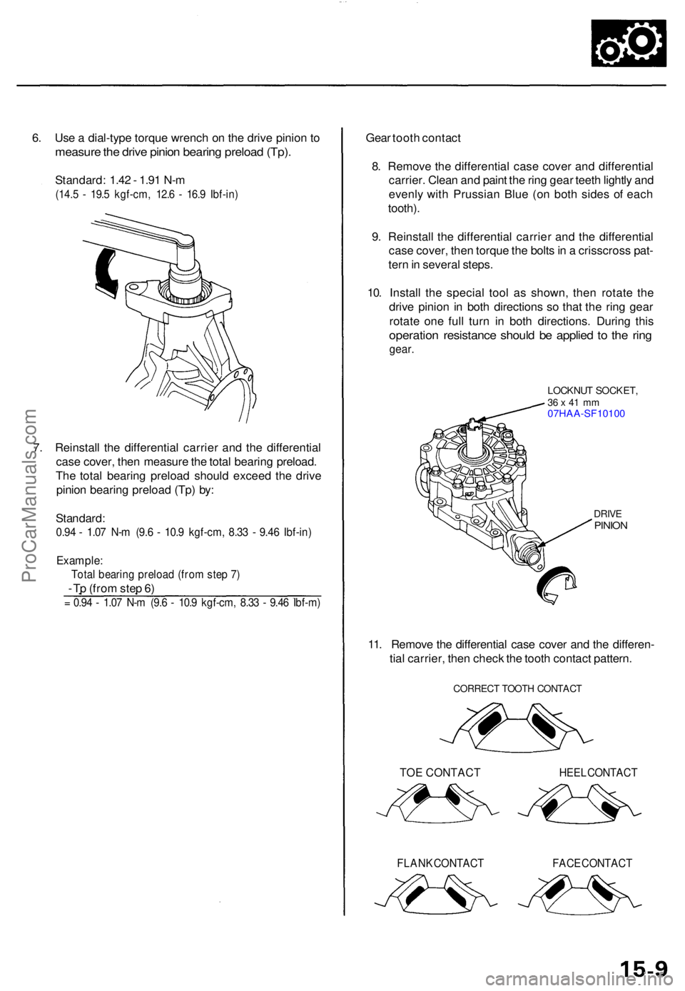
6. Us e a dial-typ e torqu e wrenc h o n th e driv e pinio n t o
measur e th e driv e pinio n bearin g preloa d (Tp) .
Standard : 1.4 2 - 1.9 1 N- m
(14. 5 - 19. 5 kgf-cm , 12. 6 - 16. 9 Ibf-in )
7. Reinstal l th e differentia l carrie r an d th e differentia l
cas e cover , the n measur e th e tota l bearin g preload .
Th e tota l bearin g preloa d shoul d excee d th e driv e
pinio n bearin g preloa d (Tp ) by :
Standard :
0.94 - 1.0 7 N- m (9. 6 - 10. 9 kgf-cm , 8.3 3 - 9.4 6 Ibf-in )
Example :
Total bearin g preloa d (fro m ste p 7 )
- T p (fro m ste p 6 )
= 0.9 4 - 1.0 7 N- m (9. 6 - 10. 9 kgf-cm , 8.3 3 - 9.4 6 Ibf-m )
Gear toot h contac t
8 . Remov e th e differentia l cas e cove r an d differentia l
carrier . Clea n an d pain t th e rin g gea r teet h lightl y an d
evenl y wit h Prussia n Blu e (o n bot h side s o f eac h
tooth) .
9 . Reinstal l th e differentia l carrie r an d th e differentia l
cas e cover , the n torqu e th e bolt s in a crisscros s pat -
ter n in severa l steps .
10 . Instal l th e specia l too l a s shown , the n rotat e th e
driv e pinio n i n bot h direction s s o tha t th e rin g gea r
rotat e on e ful l tur n i n bot h directions . Durin g thi s
operatio n resistanc e shoul d b e applie d t o th e rin g
gear .
LOCKNU T SOCKET ,36 x 41 m m07HAA-SF1010 0
DRIVEPINIO N
11. Remov e th e differentia l cas e cove r an d th e differen -
tia l carrier , the n chec k th e toot h contac t pattern .
CORREC T TOOT H CONTAC T
TOE CONTACT HEEL CONTAC T
FLANK CONTAC T FACE CONTAC T
ProCarManuals.com
Page 440 of 1771
Differential Assembly
Disassembly
1. Remove the bolts in a crisscross pattern, in several
steps, then remove the differential case cover.
DIFFERENTIAL
CASE COVER
DIFFERENTIAL CASE
2. Remove the oil seal from the differential case cover.
OIL SEAL
Replace.
DIFFERENTIAL
CASE COVER
3. Remove the bearing outer race and the 79.5 mm
thrust shim(s) from the differential case cover by heat-
ing the differential case cover to about 212°F (100°C).
NOTE:
• Do not heat the differential case cover in excess
of 212°F (100°C).
• If the bearing outer race was removed by heat-
ing, allow the differential case cover to cool to
room temperature.
• Replace the tapered roller bearing with a new
one whenever the bearing outer race is replaced.
BEARING OUTER
RACE
79.5
mm
THRUST SHIM
(1 or 2 shims)
DIFFERENTIAL CASE COVER
4. Remove the breather plate.
SCREW
Replace.
BREATHER PLATEProCarManuals.com
Page 444 of 1771
Differential Carrier
Ring Gear Replacement
1. Remove the bolts in a crisscross pattern, in several
steps, and remove the ring gear.
11 x 1.0 mm
118 N-m (12.0 kgf-m,
87 Ibf-ft)
DIFFERENTIAL
CARRIER
RING
GEAR
2. Install the ring gear by tightening the bolts in a
crisscross pattern, in several steps. If the bolts are
difficult to tighten, make sure that the ring gear is
going onto the differential carrier correctly.ProCarManuals.com