Page 94 of 1771
Hydraulic Tappets
Valve Installation
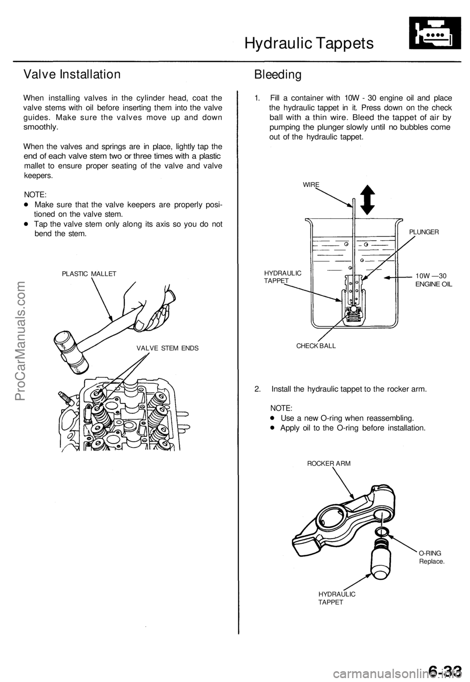
When installing valves in the cylinder head, coat the
valve stems with oil before inserting them into the valve
guides. Make sure the valves move up and down
smoothly.
When the valves and springs are in place, lightly tap the
end of each valve stem two or three times with a plastic
mallet to ensure proper seating of the valve and valve
keepers.
NOTE:
Make sure that the valve keepers are properly posi-
tioned on the valve stem.
Tap the valve stem only along its axis so you do not
bend the stem.
PLASTIC MALLET
Bleeding
VALVE STEM ENDS
1. Fill a container with 10W - 30 engine oil and place
the hydraulic tappet in it. Press down on the check
ball with a thin wire. Bleed the tappet of air by
pumping the plunger slowly until no bubbles come
out of the hydraulic tappet.
WIRE
PLUNGER
10W —30
ENGINE OIL
HYDRAULIC
TAPPET
CHECK BALL
2. Install the hydraulic tappet to the rocker arm.
NOTE:
Use a new O-ring when reassembling.
Apply oil to the O-ring before installation.
ROCKER ARM
O-RING
Replace.
HYDRAULIC
TAPPETProCarManuals.com
Page 141 of 1771
Radiator
Illustrate d Inde x
Syste m is unde r hig h pressur e whe n th e
engin e i s hot . T o avoi d dange r o f releasin g scaldin g
coolant , remov e th e ca p onl y whe n th e engin e is cool .
Tota l Coolin g Syste m Capacit y (Includin g heate r an d
reservoir )
7.7 (8. 1 US qt , 6. 8 Im p qt )
Reservoi r capacity : 0.6 5 (0.6 9 U S qt , 0.5 7 Im p qt ) CAUTION
: Whe n pourin g engin e coolant , b e sur e t o
shu t th e rela y bo x li d an d no t t o spil l coolan t o n th e elec -
trica l part s o r th e painte d portion . I f an y coolan t spills ,
rins e it of f immediately .
NOTE:
• Chec k al l coolin g syste m hose s fo r damage , leak s o r
deterioratio n an d replac e if necessary .
• Chec k al l hos e clamp s an d retighte n if necessary .
• Us e ne w O-ring s whe n reassembling .
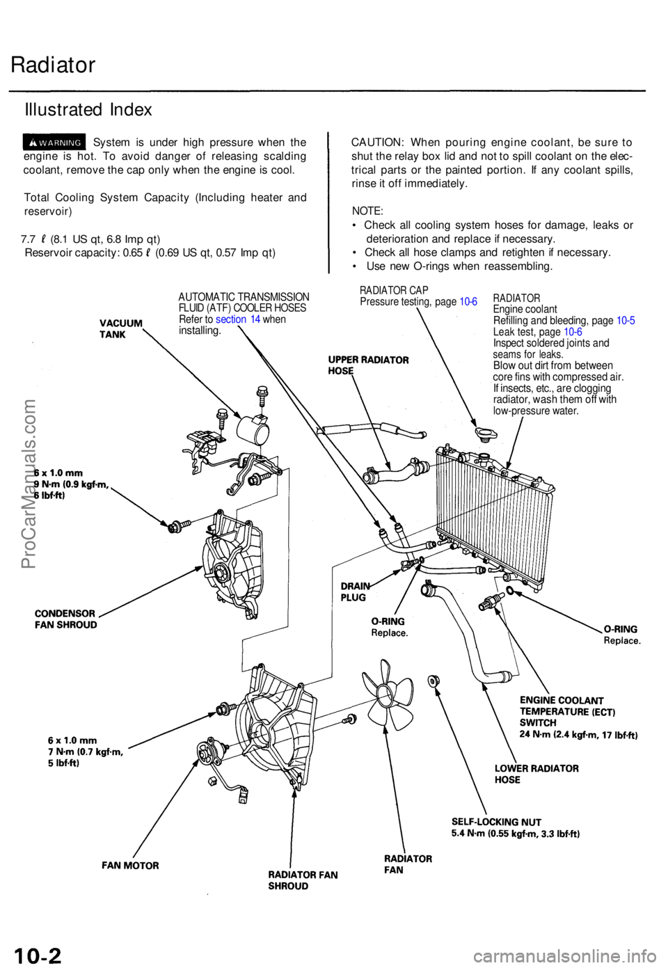
RADIATOR CA PPressur e testing , pag e 10- 6RADIATO REngine coolan t
Refillin g an d bleeding , pag e 10- 5
Leak test , pag e 10- 6Inspec t soldere d joint s an dseam s fo r leaks .Blow ou t dir t fro m betwee ncore fin s wit h compresse d air .If insects , etc. , ar e cloggin gradiator , was h the m of f wit hlow-pressur e water .
AUTOMATI C TRANSMISSIO NFLUID (ATF ) COOLE R HOSE SRefer t o sectio n 1 4 whe ninstalling .
ProCarManuals.com
Page 822 of 1771
Radiator
Illustrate d Inde x
Syste m is unde r hig h pressur e whe n th e
engin e i s hot . T o avoi d dange r o f releasin g scaldin g
coolant , remov e ca p onl y whe n th e engin e i s cool .
Total Coolin g Syste m Capacit y (Includin g heate r an d
reservoir )
7.0 (7. 4 US qt , 6. 2 Im p qt )
Reservoi r capacity : 0. 7 (0. 7 U S qt , 0. 6 Im p qt )
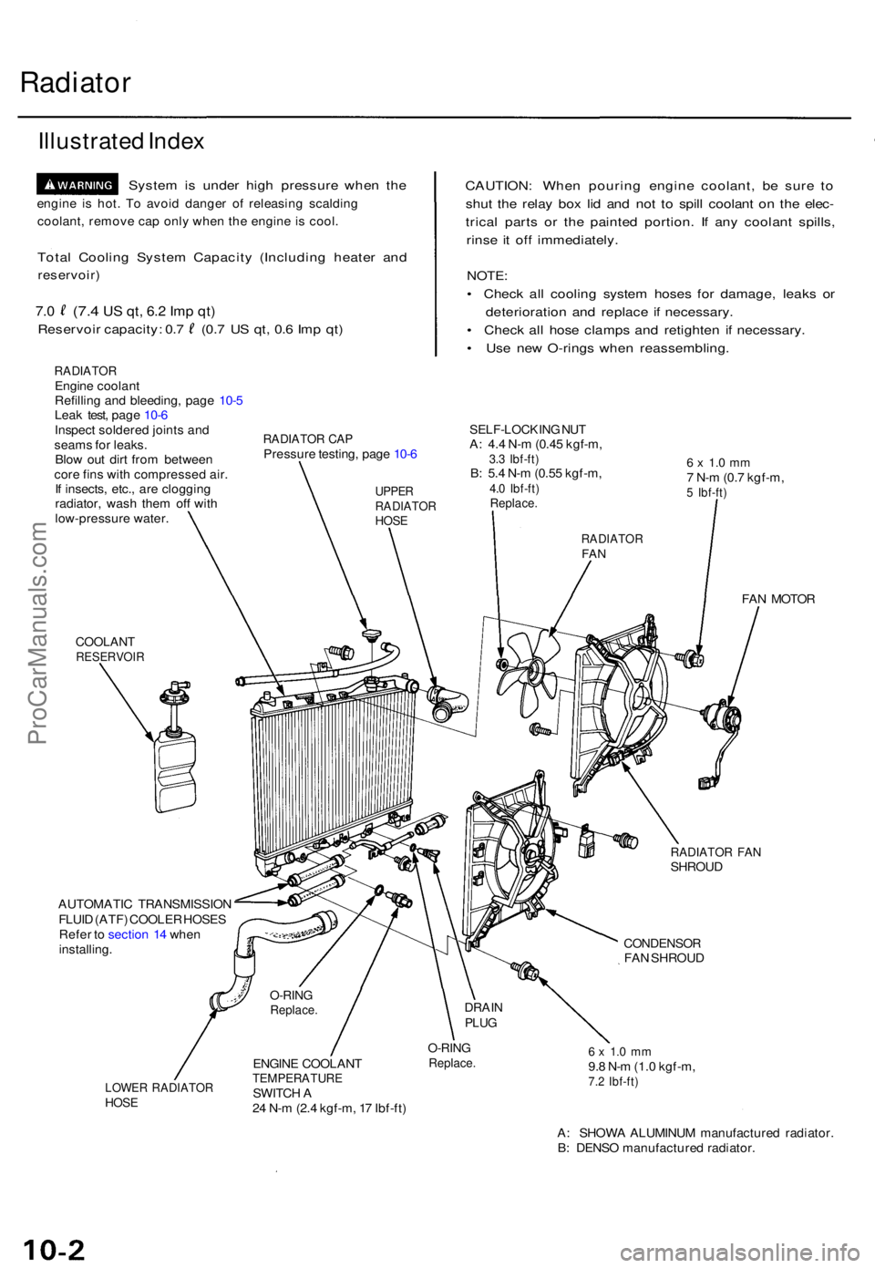
RADIATO REngine coolan t
Refillin g an d bleeding , pag e 10- 5
Lea k test , pag e 10- 6
Inspec t soldere d joint s an d
seam s fo r leaks .
Blo w ou t dir t fro m betwee n
cor e fin s wit h compresse d air .
I f insects , etc. , ar e cloggin g
radiator , was h the m of f wit h
low-pressur e water .
CAUTION : Whe n pourin g engin e coolant , b e sur e t o
shu t th e rela y bo x li d an d no t t o spil l coolan t o n th e elec -
trica l part s o r th e painte d portion . I f an y coolan t spills ,
rins e i t of f immediately .
NOTE:
• Chec k al l coolin g syste m hose s fo r damage , leak s o r
deterioratio n an d replac e i f necessary .
• Chec k al l hos e clamp s an d retighte n i f necessary .
• Us e ne w O-ring s whe n reassembling .
RADIATOR CA PPressur e testing , pag e 10- 6
SELF-LOCKIN G NU TA: 4. 4 N- m (0.4 5 kgf-m ,3.3 Ibf-ft )B: 5. 4 N- m (0.5 5 kgf-m ,4.0 Ibf-ft )Replace .
6 x 1. 0 m m7 N- m (0. 7 kgf-m ,5 Ibf-ft )
COOLAN TRESERVOI R
FAN MOTO R
RADIATO R FA NSHROU D
AUTOMATI C TRANSMISSIO N
FLUI D (ATF ) COOLE R HOSE S
Refe r t o sectio n 1 4 whe n
installing .
CONDENSO RFAN SHROU D
LOWER RADIATO RHOSE
ENGIN E COOLAN TTEMPERATUR ESWITCH A
2 4 N- m (2. 4 kgf-m , 1 7 Ibf-ft )
O-RIN GReplace .6 x 1. 0 m m9.8 N- m (1. 0 kgf-m ,7.2 Ibf-ft )
A: SHOW A ALUMINU M manufacture d radiator .
B : DENS O manufacture d radiator .
O-RINGReplace .DRAINPLUG
UPPE RRADIATO RHOSE
RADIATO RFAN
ProCarManuals.com
Page 1253 of 1771
Bleeding
CAUTION:
• Always use Genuine Honda DOT 3 Brake Fluid. Using
a non-Honda brake fluid can cause corrosion and
decrease the life of the system.
• Make sure no dirt or other foreign matter is allowed
to contaminate the brake fluid.
• Do not spill brake fluid on the vehicle, it may damage
the paint; if brake fluid does contact the paint, wash
it off immediately with water.
NOTE: The reservoir on the master cylinder must be at
the MAX (upper) level mark at the start of bleeding pro-
cedure, and checked after bleeding each brake caliper.
Add fluid as required.
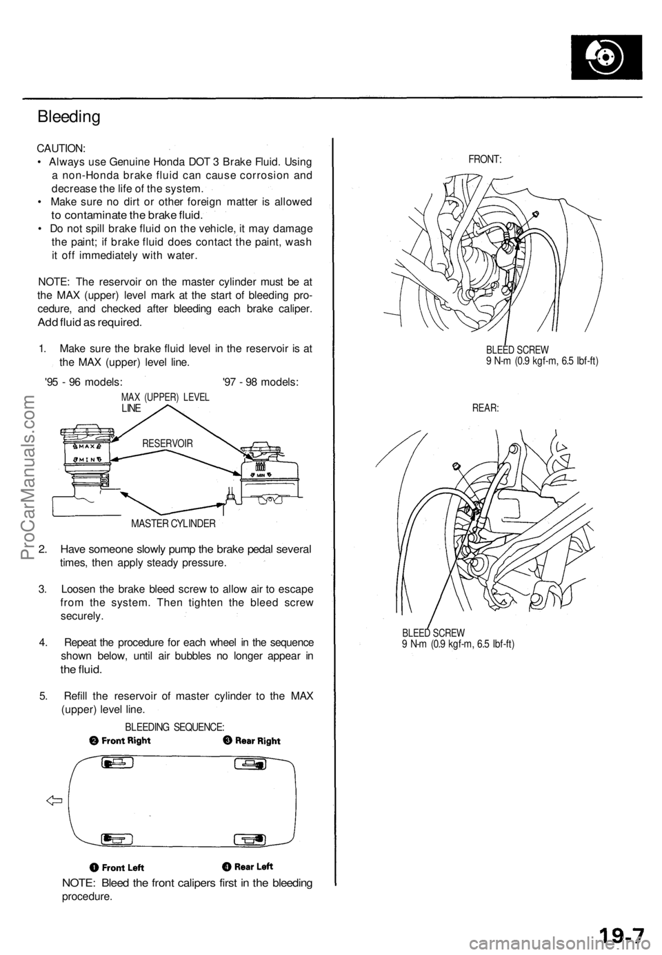
1. Make sure the brake fluid level in the reservoir is at
the MAX (upper) level line.
'95 - 96 models: '97 - 98 models:
MAX (UPPER) LEVEL
LINE
MASTER CYLINDER
2. Have someone slowly pump the brake pedal several
times, then apply steady pressure.
3. Loosen the brake bleed screw to allow air to escape
from the system. Then tighten the bleed screw
securely.
4. Repeat the procedure for each wheel in the sequence
shown below, until air bubbles no longer appear in
the fluid.
5. Refill the reservoir of master cylinder to the MAX
(upper) level line.
BLEEDING SEQUENCE:
NOTE: Bleed the front calipers first in the bleeding
procedure.
FRONT:
BLEED SCREW
9 N-m (0.9 kgf-m, 6.5 Ibf-ft)
REAR:
BLEED SCREW
9 N-m (0.9 kgf-m, 6.5 Ibf-ft)
RESERVOIRProCarManuals.com
Page 1331 of 1771
Troubleshooting Precautions
Kickback
1. The motor operates when the ABS is functioning, and the fluid in the reservoir is forced out to the master cylinder
causing kickback at the brake pedal.
Pump Motor
1. The pump motor operates when the ABS is functioning.
2. The ABS control unit checks the pump motor operation during initial diagnosis and vehicle starts. You may hear the
faint operation sound at this time, but it is normal.
Brake Fluid Replacement/Air Bleeding
1. Brake fluid replacement and air bleeding procedures are the same as vehicles without ABS. To ease bleeding, start
with the front wheels.
Troubleshooting
1. The troubleshooting flowcharts procedures assume that the cause of the problem is still present and the ABS indica-
tor light is still on. Following the flowchart when the ABS indicator light does not come on can result in incorrect
judgment.
2. Question the customer about the conditions when the problem occurred, and try to reproduce the same conditions
for troubleshooting.
Find out when the ABS indicator light came on, such as during initial diagnosis, during ABS control, after ABS con-
trol, when the vehicle started, when vehicle speed was at 19 mph (30 km/h), when the problem continued for a few
seconds or a few minutes, etc.
3. When the ABS indicator light does not come on during the test-drive, but the troubleshooting is performed based on
the DTC, check for the loose connectors, poor contact of the terminals, etc, before troubleshooting.
4. After troubleshooting, erase the DTC and test-drive the vehicle. Be sure that the ABS indicator light does not come on.
5. The connector illustrations show the female connectors with a single outline and the male connectors with a double
outline.ProCarManuals.com