1995 ACURA TL steering wheel
[x] Cancel search: steering wheelPage 28 of 1771

Lubrication Points
For the details of lubrication points and types of lubricants to be applied, refer to the illustrated index and various work
procedures (such as Assembly/Reassembly, Replacement, Overhaul, Installation, etc.) contained in each section.
No.
1
2
3
4
5
6
7
8
9
10
11
12
13
14
15
16
17
18
19
20
21
LUBRICATION POINTS
Engine
Transmission
Brake Line (Includes Anti-lock brake line)
Power steering gearbox
Steering boots
Throttle cable end
Steering ball joints
Shift lever (Automatic transmission)
Pedal linkage
Intermediate shaft
Brake master cylinder pushrod
Fuel
fill
lid
Trunk hinges
Door hinges upper and lower
Door opening detents
Hood hinges and hood latch
Brake pipe joint (Front and rear wheel house)
Caliper Piston seal, Dust seal,
Caliper pin, Piston
Power steering system
Differential
A/C compressor
LUBRICANT
API Service Grade: Use SH "Energy Conserving II" or SJ
"Energy Conserving" grade oil.
The oil container may also display the API Certification
mark shown below. Make sure it says "For Gasoline
Engines."
SAE Viscosity: See chart below.
Genuine Honda Premium Formula Automatic
Transmission Fluid (ATF)*1
Genuine Honda DOT3 Brake Fluid*2
Steering grease P/N 08733 - B070E
Multi-purpose grease
Honda White Lithium Grease
Rust preventives
Silicone grease
Genuine Honda Power Steering Fluid-V or S*3
Hypoid gear Oil API service GL4 or GL5
Viscosity:
at above -18°C (0°F): SAE 90
at less than -18°C (0°F): SAE 80 W-90
Compressor oil:
DENSO: ND-OIL8 (P/N 38897 - PR7 - A01 AH or 38899 -
PR7-A01)
(For Refrigerant: HFC-134a (R-134a))
API SERVICE LABEL
API CERTIFICATION MARK
Recommended Engine Oil
Engine oil viscosity for ambient temperature ranges
NOTE: The following information as marked *1, *2 and *3 on above chart details for 1997 model:
*1: Always use Genuine Honda Premium Formula Automatic Transmission Fluid (ATF). Using a non-Honda ATF can affect
shift quality.
*2: Always use Genuine Honda DOT3 Brake Fluid. Using a non-Honda brake fluid can cause corrosion and decrease the
life of the system.
*3: Always use Genuine Honda Power Steering Fluid-V or S. Using any other type of power steering fluid or automatic
transmission fluid can cause increase wear and poor steering in cold weather.ProCarManuals.com
Page 468 of 1771
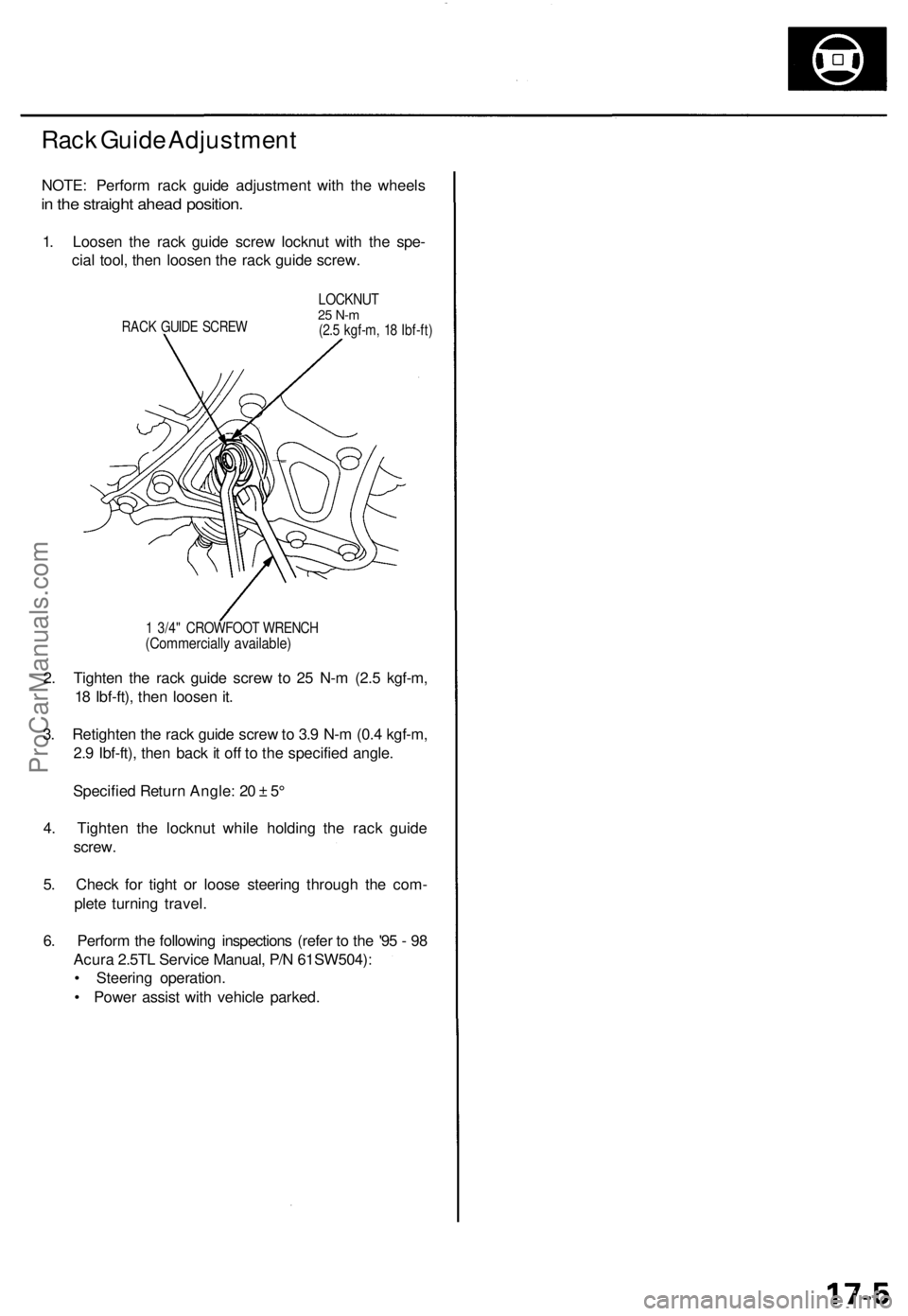
Rack Guide Adjustment
NOTE: Perform rack guide adjustment with the wheels
in the straight ahead position.
1. Loosen the rack guide screw locknut with the spe-
cial tool, then loosen the rack guide screw.
RACK GUIDE SCREW
LOCKNUT
25 N-m
(2.5 kgf-m, 18 Ibf-ft)
1 3/4" CROWFOOT WRENCH
(Commercially available)
2. Tighten the rack guide screw to 25 N-m (2.5 kgf-m,
18 Ibf-ft), then loosen it.
3. Retighten the rack guide screw to 3.9 N-m (0.4 kgf-m,
2.9 Ibf-ft), then back it off to the specified angle.
Specified Return Angle: 20 ± 5°
4. Tighten the locknut while holding the rack guide
screw.
5. Check for tight or loose steering through the com-
plete turning travel.
6. Perform the following inspections (refer to the '95 - 98
Acura 2.5TL Service Manual, P/N 61SW504):
• Steering operation.
• Power assist with vehicle parked.ProCarManuals.com
Page 473 of 1771
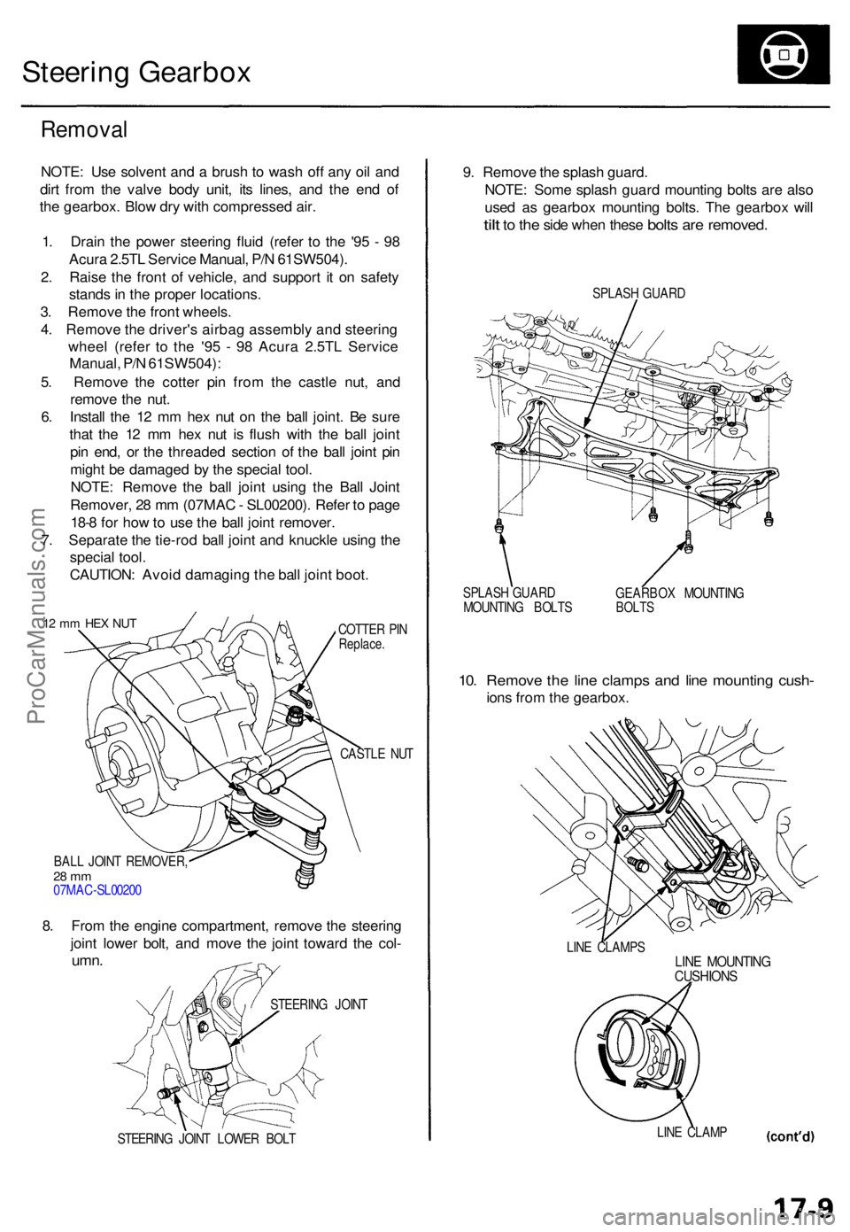
Steering Gearbo x
Remova l
NOTE: Us e solven t an d a brus h t o was h of f an y oi l an d
dir t fro m th e valv e bod y unit , it s lines , an d th e en d o f
th e gearbox . Blo w dr y wit h compresse d air .
1 . Drai n th e powe r steerin g flui d (refe r t o th e '9 5 - 9 8
Acur a 2.5T L Servic e Manual , P/ N 61SW504) .
2 . Rais e th e fron t o f vehicle , an d suppor t i t o n safet y
stand s in th e prope r locations .
3 . Remov e th e fron t wheels .
4 . Remov e th e driver' s airba g assembl y an d steerin g
whee l (refe r t o th e '9 5 - 9 8 Acur a 2.5T L Servic e
Manual , P/ N 61SW504) :
5 . Remov e th e cotte r pi n fro m th e castl e nut , an d
remov e th e nut .
6 . Instal l th e 1 2 m m he x nu t o n th e bal l joint . B e sur e
tha t th e 1 2 m m he x nu t i s flus h wit h th e bal l join t
pi n end , o r th e threade d sectio n o f th e bal l join t pi n
migh t b e damage d b y th e specia l tool .
NOTE : Remov e th e bal l join t usin g th e Bal l Join t
Remover , 2 8 m m (07MA C - SL00200) . Refe r t o pag e
18- 8 fo r ho w to us e th e bal l join t remover .
7 . Separat e th e tie-ro d bal l join t an d knuckl e usin g th e
specia l tool .
CAUTION : Avoi d damagin g th e bal l join t boot .
12 m m HE X NU TCOTTE R PI NReplace .
CASTLE NU T
BAL L JOIN T REMOVER ,
28 m m07MA C-SL0020 0
8. Fro m th e engin e compartment , remov e th e steerin g
join t lowe r bolt , an d mov e th e join t towar d th e col -
umn .
STEERIN G JOIN T LOWE R BOL T
9. Remov e th e splas h guard .
NOTE : Som e splas h guar d mountin g bolt s ar e als o
use d a s gearbo x mountin g bolts . Th e gearbo x wil l
tilt to th e sid e whe n thes e bolts are removed .
SPLASH GUAR D
SPLAS H GUAR D
MOUNTIN G BOLT S GEARBO
X MOUNTIN G
BOLTS
10. Remov e th e lin e clamp s an d lin e mountin g cush -
ions fro m th e gearbox .
LINE CLAMP SLINE MOUNTIN GCUSHIONS
LINE CLAM P
STEERIN
G JOIN T
ProCarManuals.com
Page 486 of 1771
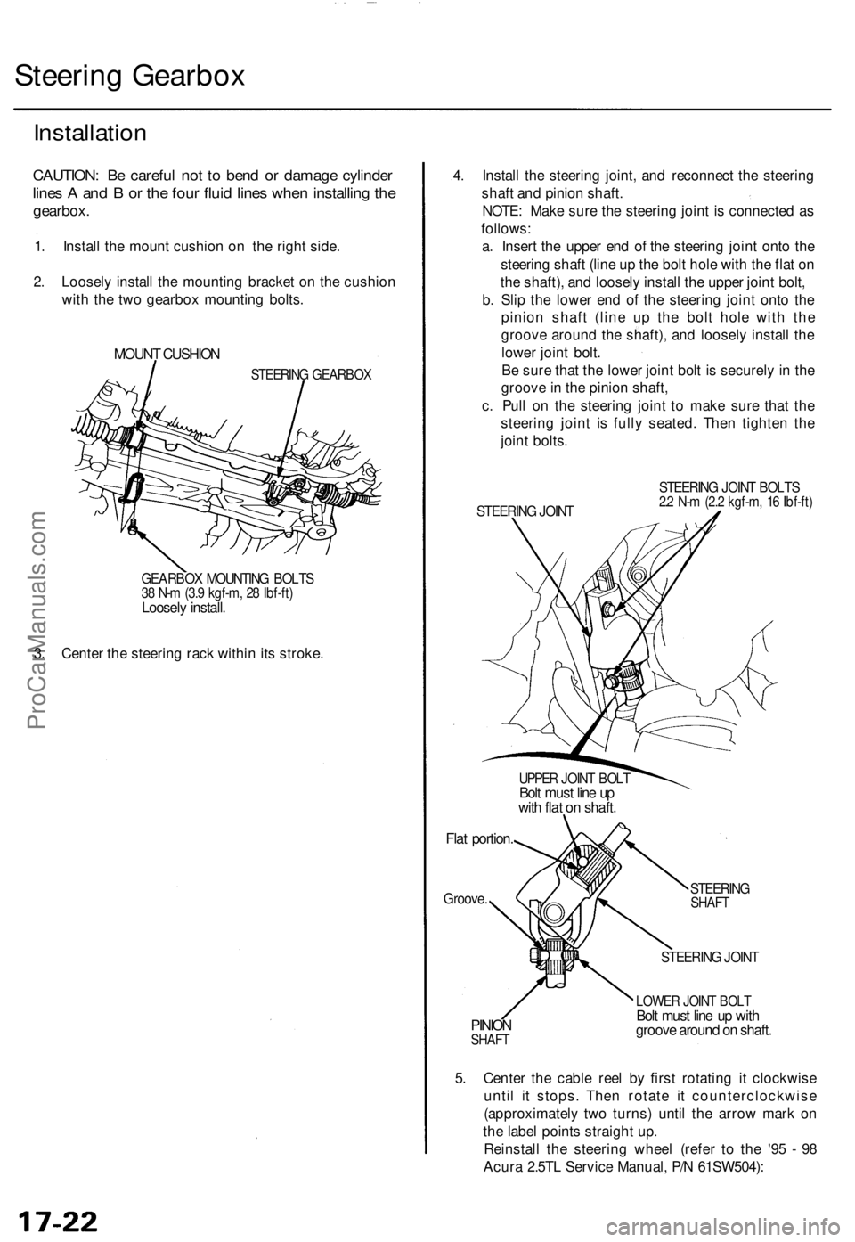
Steering Gearbox
Installation
CAUTION: Be careful not to bend or damage cylinder
lines A and B or the four fluid lines when installing the
gearbox.
1. Install the mount cushion on the right side.
2. Loosely install the mounting bracket on the cushion
with the two gearbox mounting bolts.
MOUNT CUSHION
STEERING GEARBOX
GEARBOX MOUNTING BOLTS
38 N-m (3.9 kgf-m, 28 Ibf-ft)
Loosely install.
3. Center the steering rack within its stroke.
4. Install the steering joint, and reconnect the steering
shaft and pinion shaft.
NOTE: Make sure the steering joint is connected as
follows:
a. Insert the upper end of the steering joint onto the
steering shaft (line up the bolt hole with the flat on
the shaft), and loosely install the upper joint bolt,
b. Slip the lower end of the steering joint onto the
pinion shaft (line up the bolt hole with the
groove around the shaft), and loosely install the
lower joint bolt.
Be sure that the lower joint bolt is securely in the
groove in the pinion shaft,
c. Pull on the steering joint to make sure that the
steering joint is fully seated. Then tighten the
joint bolts.
STEERING JOINT
STEERING JOINT BOLTS
2.2 N-m (2.2 kgf-m, 16 Ibf-ft)
UPPER JOINT BOLT
Bolt must line up
with flat on shaft.
Flat portion.
Groove.
STEERING
SHAFT
PINION
SHAFT
STEERING JOINT
LOWER JOINT BOLT
Bolt must line up with
groove around on shaft.
5. Center the cable reel by first rotating it clockwise
until it stops. Then rotate it counterclockwise
(approximately two turns) until the arrow mark on
the label points straight up.
Reinstall the steering wheel (refer to the '95 - 98
Acura 2.5TL Service Manual, P/N 61SW504):ProCarManuals.com
Page 488 of 1771
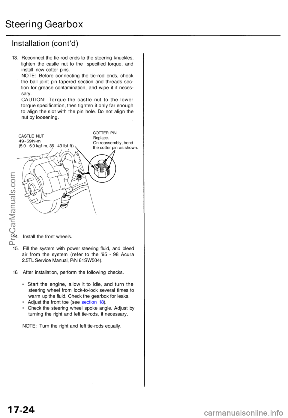
Steering Gearbo x
Installatio n (cont'd )
13. Reconnec t th e tie-ro d end s t o th e steerin g knuckles ,
tighte n th e castl e nu t t o th e specifie d torque , an d
instal l ne w cotte r pins .
NOTE : Befor e connectin g th e tie-ro d ends , chec k
th e bal l join t pi n tapere d sectio n an d thread s sec -
tio n fo r greas e contamination , an d wip e i t i f neces -
sary.
CAUTION : Torqu e th e castl e nu t t o th e lowe r
torqu e specification , the n tighte n it onl y fa r enoug h
t o alig n th e slo t wit h th e pi n hole . D o no t alig n th e
nu t b y loosening .
14 . Instal l th e fron t wheels .
15 . Fil l th e syste m wit h powe r steerin g fluid , an d blee d
ai r fro m th e syste m (refe r t o th e '9 5 - 9 8 Acur a
2.5T L Servic e Manual , P/ N 61SW504) .
16 . Afte r installation , perfor m th e followin g checks .
• Star t th e engine , allo w it t o idle , an d tur n th e
steerin g whee l fro m lock-to-loc k severa l time s t o
war m u p th e fluid . Chec k th e gearbo x fo r leaks .
• Adjus t th e fron t to e (se e sectio n 18 ).
• Chec k th e steerin g whee l spok e angle . Adjus t b y
turning the righ t an d lef t tie-rods , i f necessary .
NOTE : Tur n th e righ t an d lef t tie-rod s equally .
CASTLE NU T49 - 5 9 N- m(5. 0 - 6. 0 kgf-m , 3 6 - 4 3 Ibf-ft )
COTTE R PI NReplace .On reassembly , ben d
th e cotte r pi n a s shown .
ProCarManuals.com
Page 530 of 1771
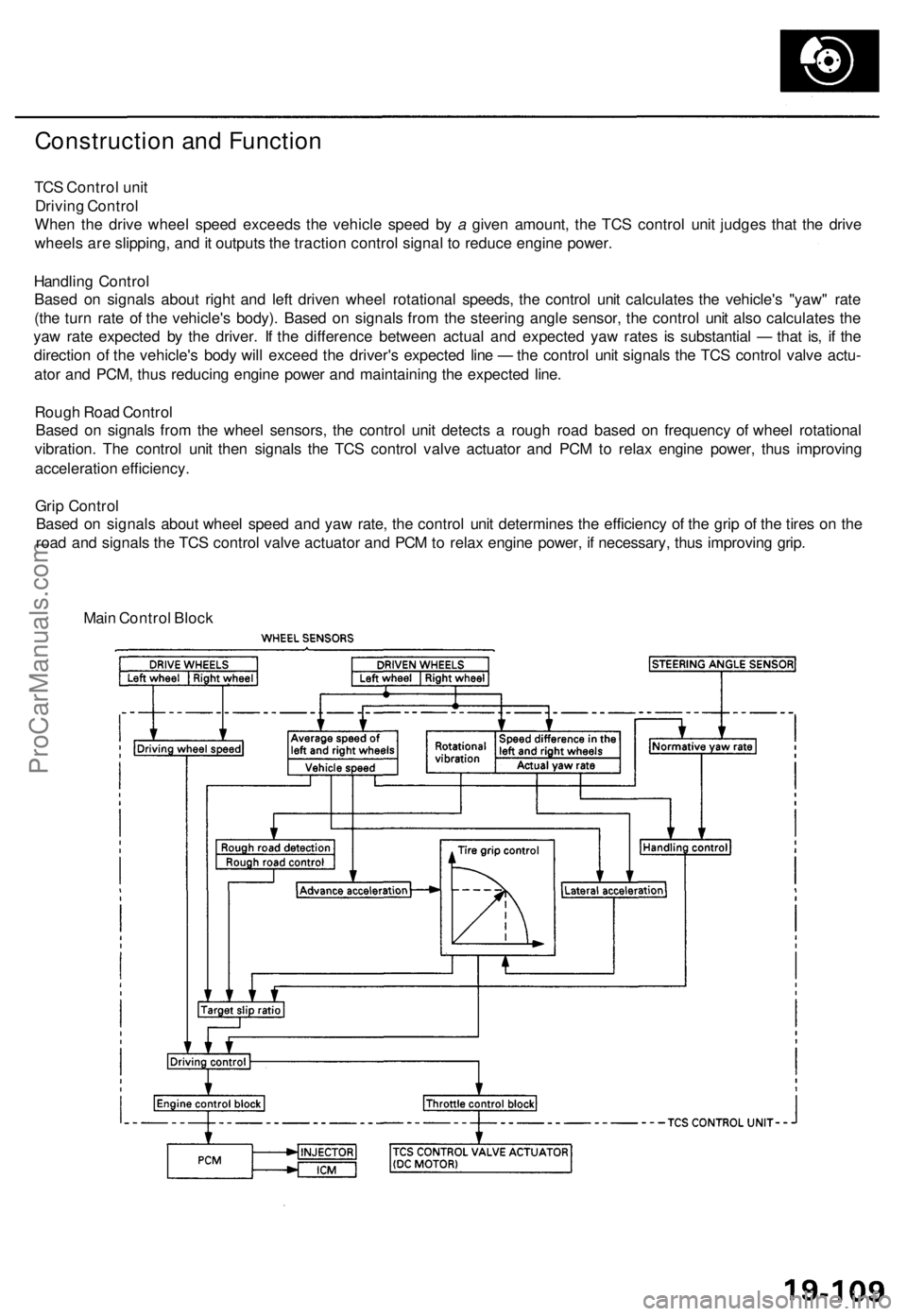
Construction and Function
TCS Control unit
Driving Control
When the drive wheel speed exceeds the vehicle speed by a given amount, the TCS control unit judges that the drive
wheels are slipping, and it outputs the traction control signal to reduce engine power.
Handling Control
Based on signals about right and left driven wheel rotational speeds, the control unit calculates the vehicle's "yaw" rate
(the turn rate of the vehicle's body). Based on signals from the steering angle sensor, the control unit also calculates the
yaw rate expected by the driver. If the difference between actual and expected yaw rates is substantial — that is, if the
direction of the vehicle's body will exceed the driver's expected line — the control unit signals the TCS control valve actu-
ator and PCM, thus reducing engine power and maintaining the expected line.
Rough Road Control
Based on signals from the wheel sensors, the control unit detects a rough road based on frequency of wheel rotational
vibration. The control unit then signals the TCS control valve actuator and PCM to relax engine power, thus improving
acceleration efficiency.
Grip Control
Based on signals about wheel speed and yaw rate, the control unit determines the efficiency of the grip of the tires on the
road and signals the TCS control valve actuator and PCM to relax engine power, if necessary, thus improving grip.
Main Control BlockProCarManuals.com
Page 651 of 1771
Precautions/Procedures
Steering-related Precaution s
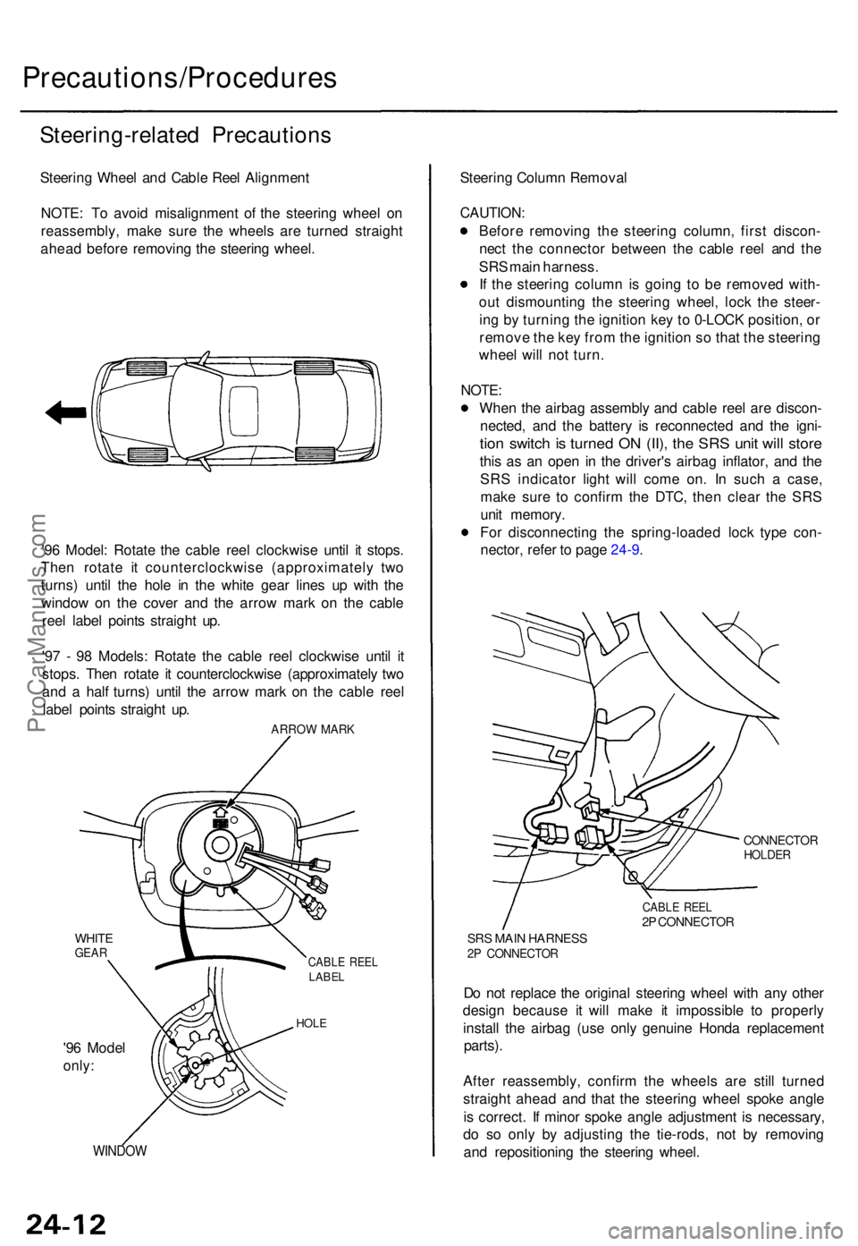
Steering Whee l an d Cabl e Ree l Alignmen t
NOTE : T o avoi d misalignmen t o f th e steerin g whee l o n
reassembly , mak e sur e th e wheel s ar e turne d straigh t
ahea d befor e removin g th e steerin g wheel .
'9 6 Model : Rotat e th e cabl e ree l clockwis e unti l i t stops .
The n rotat e i t counterclockwis e (approximatel y tw o
turns ) unti l th e hol e i n th e whit e gea r line s u p wit h th e
windo w o n th e cove r an d th e arro w mar k o n th e cabl e
ree l labe l point s straigh t up .
'9 7 - 9 8 Models : Rotat e th e cabl e ree l clockwis e unti l i t
stops . The n rotat e i t counterclockwis e (approximatel y tw o
an d a hal f turns ) unti l th e arro w mar k o n th e cabl e ree l
labe l point s straigh t up .
ARRO W MAR K
WHITEGEARCABL E REE LLABE L
HOLE
'96 Mode l
only:
WINDO W
Steering Colum n Remova l
CAUTION :
Before removin g th e steerin g column , firs t discon -
nec t th e connecto r betwee n th e cabl e ree l an d th e
SR S mai n harness .
I f th e steerin g colum n is goin g t o b e remove d with -
ou t dismountin g th e steerin g wheel , loc k th e steer -
in g b y turnin g th e ignitio n ke y t o 0-LOC K position , o r
remov e th e ke y fro m th e ignitio n s o tha t th e steerin g
whee l wil l no t turn .
NOTE :
Whe n th e airba g assembl y an d cabl e ree l ar e discon -
nected , an d th e batter y i s reconnecte d an d th e igni -
tion switc h is turne d O N (II) , th e SR S uni t wil l stor e
this a s a n ope n i n th e driver' s airba g inflator , an d th e
SR S indicato r ligh t wil l com e on . I n suc h a case ,
mak e sur e t o confir m th e DTC , the n clea r th e SR S
uni t memory .
Fo r disconnectin g th e spring-loade d loc k typ e con -
nector , refe r t o pag e 24-9 .
CONNECTO RHOLDER
CABLE REE L2P CONNECTO R
SRS MAI N HARNES S2P CONNECTO R
Do no t replac e th e origina l steerin g whee l wit h an y othe r
desig n becaus e i t will mak e i t impossibl e t o properl y
instal l th e airba g (us e onl y genuin e Hond a replacemen t
parts).
After reassembly , confir m th e wheel s ar e stil l turne d
straigh t ahea d an d tha t th e steerin g whee l spok e angl e
i s correct . I f mino r spok e angl e adjustmen t i s necessary ,
d o s o onl y b y adjustin g th e tie-rods , no t b y removin g
an d repositionin g th e steerin g wheel .
ProCarManuals.com
Page 658 of 1771
Airbag
Replacement
After a collision in which the airbags were deployed, the
airbag assemblies and the SRS unit must be replaced.
Store a removed airbag assembly with
the pad surface up. If the airbag is improperly stored
face down, accidental deployment could propel the unit
with enough force to cause serious injury.
CAUTION:
Always disconnect the airbag connectors when the
SRS main harness is disconnected.
'96 Model: Always keep the short connector (RED) on
the passenger's airbag when the harness is discon-
nected.
Do not disassemble or tamper with the airbag.
NOTE:
Do not install used SRS parts from another vehicle.
When repairing, use only new SRS parts.
Carefully inspect the airbag before you install it. Do
not install an airbag that shows signs of being
dropped or improperly handled, such as dents, cracks
or deformation.
1. Make sure you have the anti-theft code for the radio,
then write down the frequencies for the radio's pre-
set buttons.
2. Disconnect the battery negative cable, then discon-
nect the positive cable from the battery, and wait at
least three minutes.
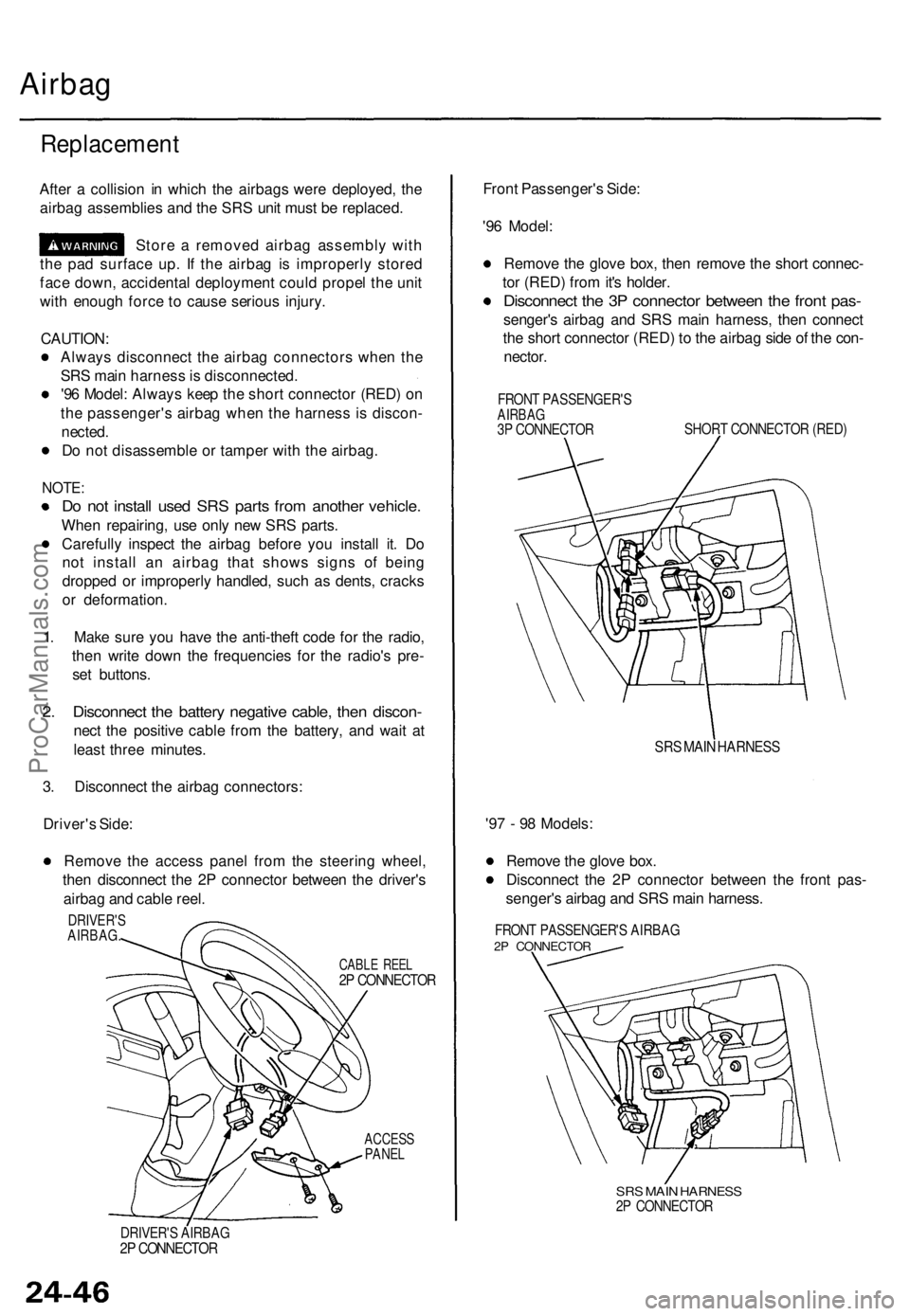
3. Disconnect the airbag connectors:
Driver's Side:
Remove the access panel from the steering wheel,
then disconnect the 2P connector between the driver's
airbag and cable reel.
ACCESS
PANEL
Front Passenger's Side:
'96 Model:
Remove the glove box, then remove the short connec-
tor (RED) from it's holder.
Disconnect the 3P connector between the front pas-
senger's airbag and SRS main harness, then connect
the short connector (RED) to the airbag side of the con-
nector.
FRONT PASSENGER'S
AIRBAG
3P CONNECTOR
SHORT CONNECTOR (RED)
SRS MAIN HARNESS
'97 - 98 Models:
Remove the glove box.
Disconnect the 2P connector between the front pas-
senger's airbag and SRS main harness.
FRONT PASSENGER'S AIRBAG
2P CONNECTOR
SRS MAIN HARNESS
2P CONNECTOR
DRIVER'S AIRBAG
2P CONNECTOR
CABLE REEL
2P CONNECTOR
DRIVER'S
AIRBAG.ProCarManuals.com