1995 ACURA TL steering wheel
[x] Cancel search: steering wheelPage 1162 of 1771
Inspection an d Adjustmen t
Steering Operatio n
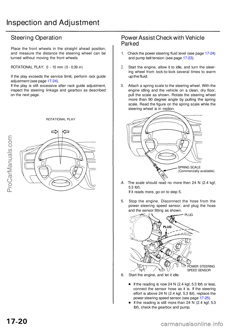
Place th e fron t wheel s i n th e straigh t ahea d position ,
an d measur e th e distanc e th e steerin g whee l ca n b e
turne d withou t movin g th e fron t wheels .
ROTATIONA L PLAY : 0 - 10 m m (0 - 0.3 9 in )
If th e pla y exceed s the servic e limit, perfor m rack guid e
adjustmen t (se e pag e 17-24 ).
I f th e pla y i s stil l excessiv e afte r rac k guid e adjustment ,
inspec t th e steerin g linkag e an d gearbo x a s describe d
o n th e nex t page .
ROTATIONA L PLA Y
Powe r Assis t Chec k wit h Vehicl e
Parked
1. Chec k th e powe r steerin g flui d leve l (se e pag e 17-24 )
an d pum p bel t tensio n (se e pag e 17-23 ).
2 .
3 .
Star t th e engine , allo w it t o idle , an d tur n th e steer -
in g whee l fro m lock-to-loc k severa l time s t o war m
up th e fluid .
Attac h a sprin g scal e to th e steerin g wheel . Wit h th e
engin e idlin g an d th e vehicl e o n a clean , dr y floor ,
pul l th e scal e a s shown . Rotat e th e steerin g whee l
more tha n 9 0 degre e angl e b y pullin g th e sprin g
scale. Rea d th e figur e o n th e sprin g scal e whil e th e
steerin g whee l i s i n motion .
SPRING SCAL E(Commerciall y available )
A. Th e scal e shoul d rea d n o mor e the n 2 4 N (2. 4 kgf ,
5.3 Ibf) .
If i t read s more , g o o n t o ste p 5 .
5 . Sto p th e engine . Disconnec t th e hos e fro m th e
powe r steerin g spee d sensor , an d plu g th e hos e
an d th e senso r fittin g a s shown .
PLUG
POWE R STEERIN GSPEED SENSO R
6. Star t th e engine , an d le t i t idle .
I f th e readin g is no w 2 4 N (2. 4 kgf , 5. 3 Ibf ) o r less ,
connec t th e senso r hos e a s i t is . I f th e steerin g
effor t i s abov e 2 4 N (2. 4 kgf , 5. 3 Ibf) , replac e th e
powe r steerin g spee d senso r (se e pag e 17-25 ).
I f th e readin g i s stil l mor e tha n 2 4 N (2. 4 kgf , 5. 3
Ibf) , chec k th e gearbo x an d pump .
ProCarManuals.com
Page 1170 of 1771
Steering Whee l
Remova l (cont'd )
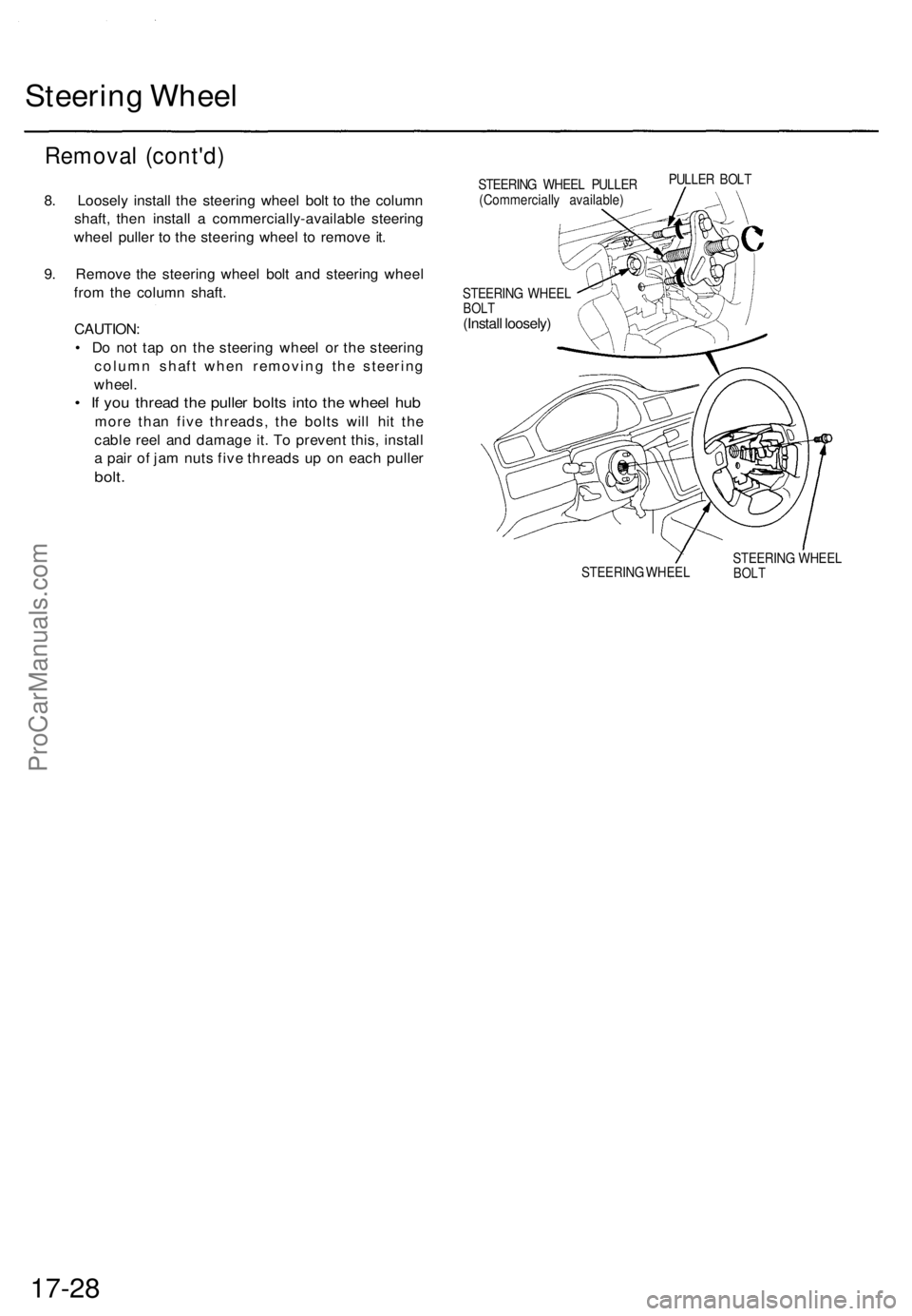
8. Loosel y instal l th e steerin g whee l bol t t o th e colum n
shaft , the n instal l a commercially-availabl e steerin g
whee l pulle r t o th e steerin g whee l t o remov e it .
9 . Remov e th e steerin g whee l bol t an d steerin g whee l
fro m th e colum n shaft .
CAUTION :
• D o no t ta p o n th e steerin g whee l o r th e steerin g
colum n shaf t whe n removin g th e steerin g
wheel .
• I f yo u threa d th e pulle r bolt s int o th e whee l hu b
mor e tha n fiv e threads , th e bolt s wil l hi t th e
cabl e ree l an d damag e it . T o preven t this , instal l
a pai r o f ja m nut s fiv e thread s u p o n eac h pulle r
bolt.
STEERIN G WHEE LBOLT(Instal l loosely )
STEERIN G WHEE L STEERIN
G WHEE LBOLT
17-28
STEERIN G WHEE L PULLE R
(Commerciall y available )PULLE
R BOL T
ProCarManuals.com
Page 1171 of 1771
Steering Whee l
Disassembly/Reassembl y
Store a remove d airba g assembl y with
the pa d surfac e up . I f th e airba g i s improperl y store d
face down , accidenta l deploymen t coul d prope l th e uni t
with enoug h forc e to caus e seriou s injury .
NOTE: I f a n intac t airba g assembl y ha s bee n remove d
from a scrappe d vehicle , o r ha s bee n foun d defectiv e o r
damage d durin g transit , storag e o r service , i t shoul d b e
deploye d (se e sectio n 24 ).
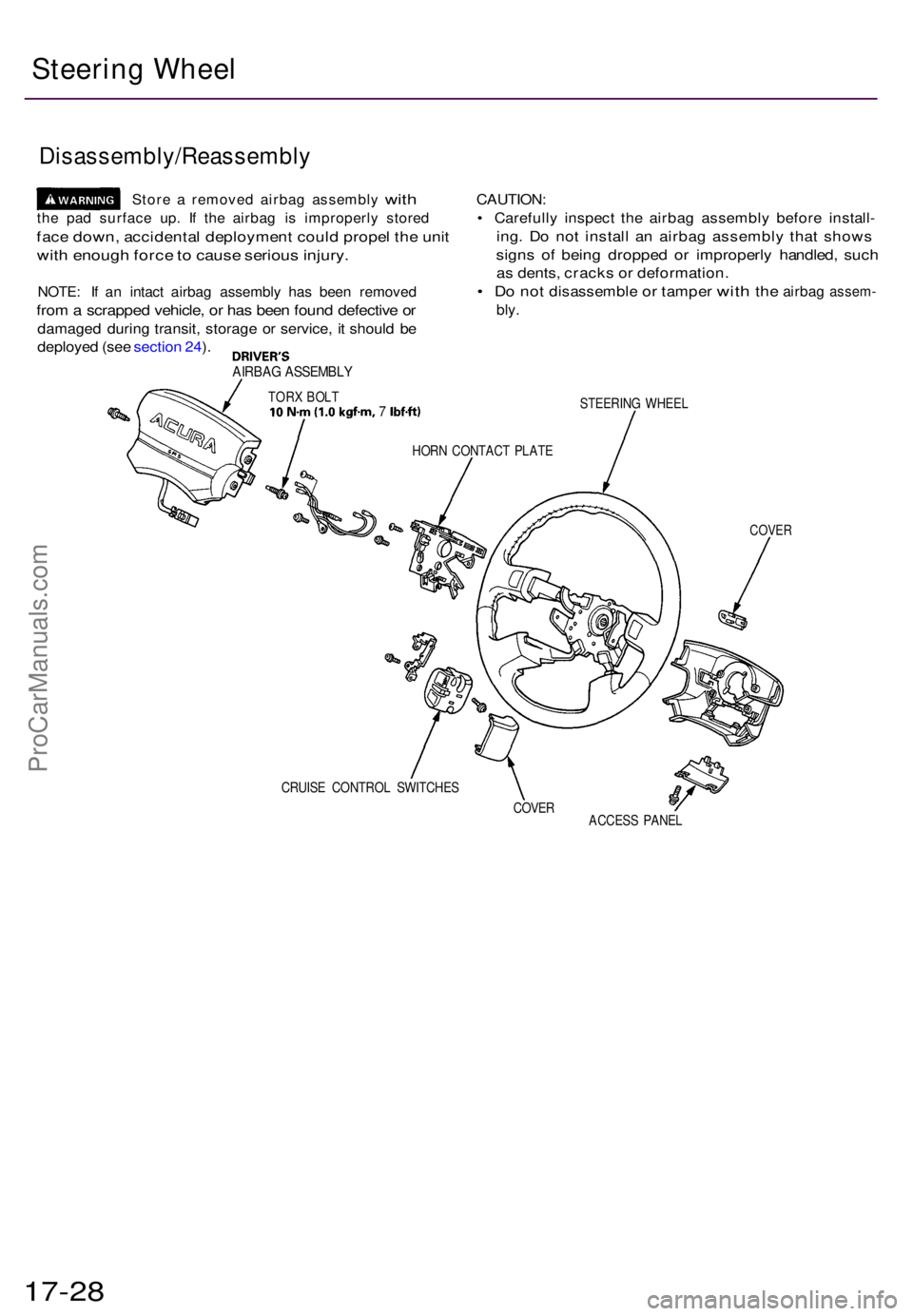
AIRBA G ASSEMBL Y
TORX BOL T10N-m d.Okgfm , 7 Ibf-ft)
CAUTION :
• Carefull y inspec t th e airba g assembl y befor e install -
ing. D o no t instal l a n airba g assembl y tha t show s
signs o f bein g droppe d o r improperl y handled , suc h
as dents , crack s o r deformation .
• D o no t disassembl e or tampe r with the airba g assem -
bly.
STEERIN G WHEE L
HOR N CONTAC T PLAT E
COVER
CRUIS E CONTRO L SWITCHE S
COVER
ACCESS PANE L
17-28
Steering Wheel
ProCarManuals.com
Page 1172 of 1771
Installation
Airbag installation
CAUTION:
• Before installing the steering wheel, align the front
wheels straight ahead.
• Be sure to install the harness wires so that they are
not pinched or interfering with other vehicle parts.
• Do not replace the original steering wheel with any
other design, since it will make it impossible to prop-
erly install the airbag. (Only use genuine Honda
replacement parts)
• After reassembly, confirm that the wheels are still
straight ahead and that steering wheel spoke angle
is correct. If minor spoke angle adjustment is neces-
sary, do so only by adjustment of the tie-rods, not by
removing and repositioning the steering wheel.
Confirm that the airbag assembly is
securely attached to the steering wheel; otherwise,
severe personal injury could result during airbag
deployment.
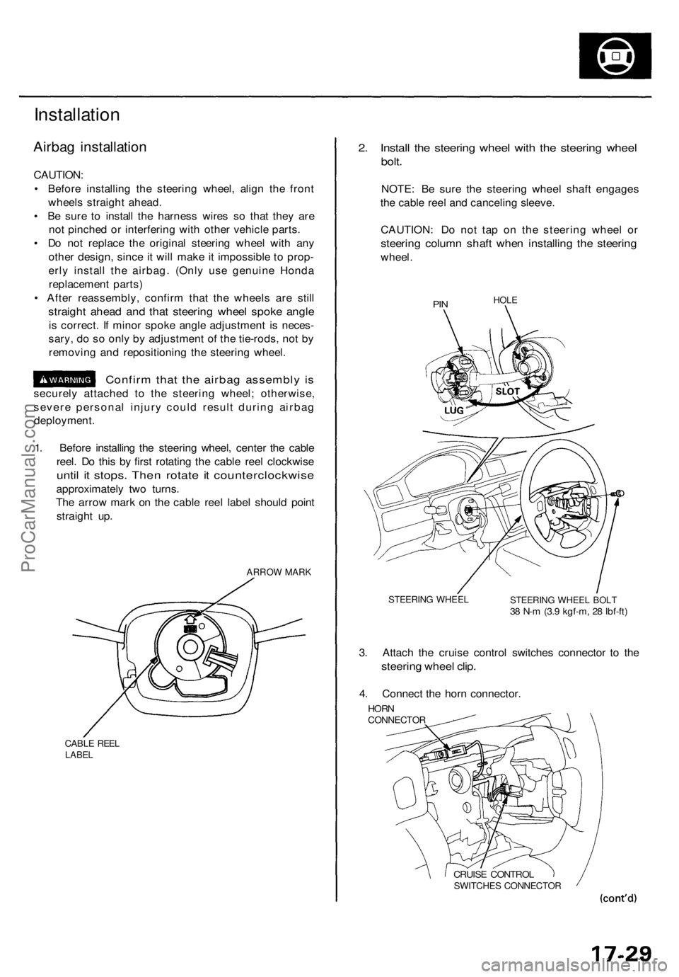
1. Before installing the steering wheel, center the cable
reel. Do this by first rotating the cable reel clockwise
until it stops. Then rotate it counterclockwise
approximately two turns.
The arrow mark on the cable reel label should point
straight up.
ARROW MARK
CABLE REEL
LABEL
2. Install the steering wheel with the steering wheel
bolt.
NOTE: Be sure the steering wheel shaft engages
the cable reel and canceling sleeve.
CAUTION: Do not tap on the steering wheel or
steering column shaft when installing the steering
wheel.
PIN
HOLE
STEERING WHEEL
STEERING WHEEL BOLT
38 N-m (3.9 kgf-m, 28 Ibf-ft)
3. Attach the cruise control switches connector to the
steering wheel clip.
4. Connect the horn connector.
HORN
CONNECTOR
CRUISE CONTROL
SWITCHES CONNECTORProCarManuals.com
Page 1191 of 1771
Steering Gearbo x
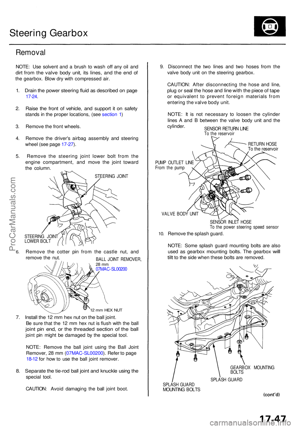
Remova l
NOTE: Us e solven t an d a brus h t o was h of f an y oi l an d
dirt fro m th e valv e bod y unit , it s lines , an d th e en d o f
the gearbox . Blo w dr y wit h compresse d air .
1. Drai n th e powe r steerin g flui d a s describe d o n pag e
17-24 .
2. Rais e th e fron t o f vehicle , an d suppor t i t o n safet y
stands in th e prope r locations , (se e sectio n 1 )
3 . Remov e th e fron t wheels .
4 . Remov e th e driver' s airba g assembl y an d steerin g
whee l (se e pag e 17-27 ).
5 . Remov e th e steerin g join t lowe r bol t fro m th e
engin e compartment , an d mov e th e join t towar d
th e column .
STEERIN G JOIN T
6.
STEERIN G JOIN T
LOWE R BOL T
Remov e th e cotte r pi n fro m th e castl e nut , an d
remov e th e nut .
12 m m HE X NU T
7. Instal l th e 1 2 m m he x nu t o n th e bal l joint .
Be sur e tha t th e 1 2 m m he x nu t i s flus h wit h th e bal l
joint pi n end , o r th e threade d sectio n o f th e bal l
joint pi n migh t b e damage d b y th e specia l tool .
NOTE : Remov e th e bal l join t usin g th e Bal l Join t
Remover , 2 8 m m (07MA C-SL00200 ). Refe r t o pag e
18-12 for ho w to us e th e bal l join t remover .
8. Separat e th e tie-ro d bal l join t an d knuckl e usin g th e
specia l tool .
CAUTION : Avoi d damagin g th e bal l join t boot . 9
. Disconnec t th e tw o line s an d tw o hose s fro m th e
valv e bod y uni t o n th e steerin g gearbox .
CAUTION : Afte r disconnectin g th e hos e an d line ,
plug o r sea l th e hos e an d lin e wit h th e piec e o f tap e
or equivalen t t o preven t foreig n material s fro m
enterin g th e valv e bod y unit .
NOTE : I t i s no t necessar y t o loose n th e cylinde r
line s A an d B betwee n th e valv e bod y uni t an d th e
cylinder .
SENSOR RETUR N LIN ETo th e reservoi r
RETURN HOS E
To th e reservoi r
PUMP OUTLE T LIN E
Fro m th e pum p
VALV E BOD Y UNI T
10.
SENSO R INLE T HOS E
T o th e powe r steerin g spee d senso r
Remove th e splas h guard .
NOTE : Som e splas h guar d mountin g bolt s ar e als o
use d
as gearbo x mountin g bolts. The gearbo x will
til t
to th e sid e whe n thes e bolts are removed .
GEARBO X MOUNTIN G
BOLT S
SPLAS H GUAR D
SPLAS H GUAR D
MOUNTIN G BOLT S
BALL JOIN T REMOVER ,28 m m07MA C-SL0020 0
ProCarManuals.com
Page 1213 of 1771
Steering Gearbo x
Installatio n (cont'd )
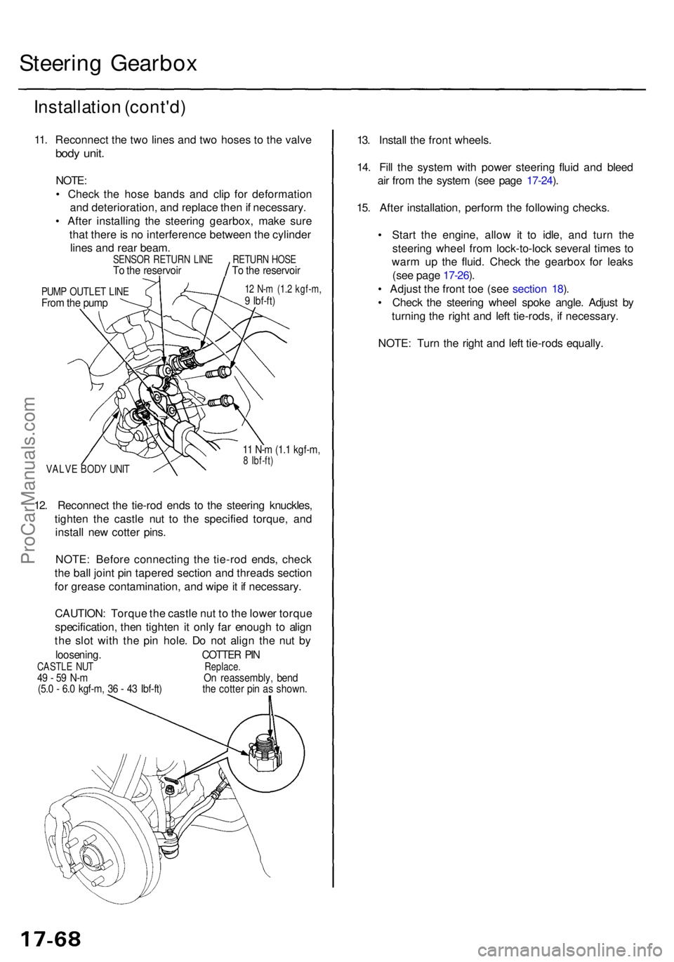
11. Reconnec t th e tw o line s an d tw o hose s t o th e valv e
body unit .
NOTE :
• Chec k th e hos e band s an d cli p fo r deformatio n
an d deterioration , an d replac e the n if necessary .
• Afte r installin g th e steerin g gearbox , mak e sur e
tha t ther e is n o interferenc e betwee n th e cylinde r
line s an d rea r beam .
PUMP OUTLE T LIN EFrom th e pum p
12 N- m (1. 2 kgf-m ,9 Ibf-ft )
VALV E BOD Y UNI T
11 N- m (1. 1 kgf-m ,8 Ibf-ft )
12. Reconnec t th e tie-ro d end s t o th e steerin g knuckles ,
tighte n th e castl e nu t t o th e specifie d torque , an d
instal l ne w cotte r pins .
NOTE : Befor e connectin g th e tie-ro d ends , chec k
th e bal l join t pi n tapere d sectio n an d thread s sectio n
fo r greas e contamination , an d wip e it i f necessary .
CAUTION : Torqu e th e castl e nu t t o th e lowe r torqu e
specification , the n tighte n it onl y fa r enoug h t o alig n
th e slo t wit h th e pi n hole . D o no t alig n th e nu t b y
loosening . COTTER PI NCASTL E NU T Replace.49 - 5 9 N- m O n reassembly , ben d(5.0 - 6. 0 kgf-m , 3 6 - 4 3 Ibf-ft ) th e cotte r pi n a s shown .
13. Instal l th e fron t wheels .
14 . Fil l th e syste m wit h powe r steerin g flui d an d blee d
ai r fro m th e syste m (se e pag e 17-24 ).
15 . Afte r installation , perfor m th e followin g checks .
• Star t th e engine , allo w i t t o idle , an d tur n th e
steerin g whee l fro m lock-to-loc k severa l time s t o
war m u p th e fluid . Chec k th e gearbo x fo r leak s
(se e pag e 17-26 ).
• Adjus t th e fron t to e (se e sectio n 18 ).
• Chec k th e steerin g whee l spok e angle . Adjus t b y
turnin g th e righ t an d lef t tie-rods , i f necessary .
NOTE : Tur n th e righ t an d lef t tie-rod s equally .
SENSO R RETUR N LIN ETo th e reservoi rRETURN HOS ETo th e reservoi r
ProCarManuals.com
Page 1553 of 1771
Ignition Switch
Steering Lock Replacement (cont'd)
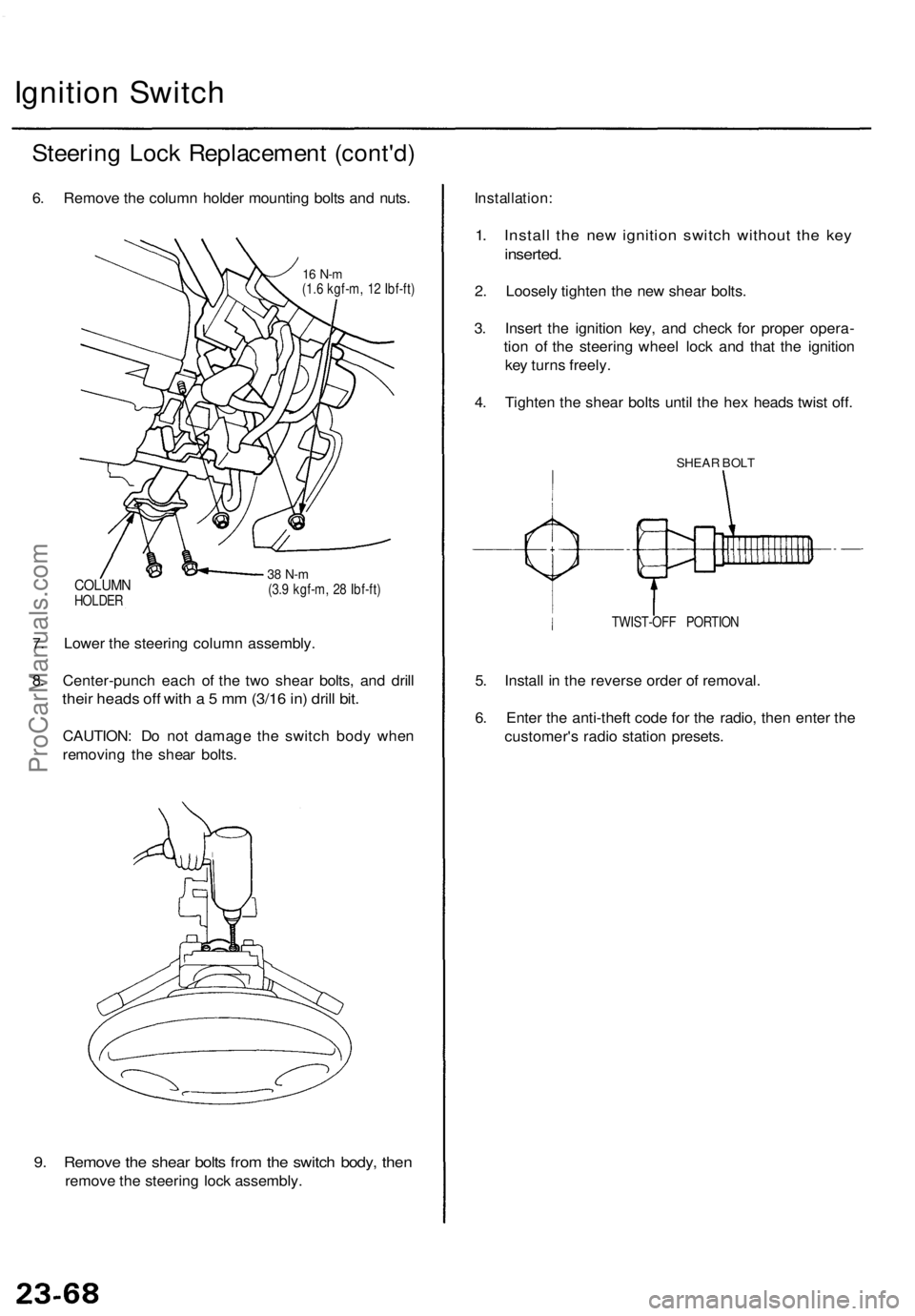
6. Remove the column holder mounting bolts and nuts.
16 N-m
(1.6 kgf-m, 12 Ibf-ft)
COLUMN
HOLDER
38 N-m
(3.9 kgf-m, 28 Ibf-ft)
7. Lower the steering column assembly.
8. Center-punch each of the two shear bolts, and drill
their heads off with a 5 mm (3/16 in) drill bit.
CAUTION: Do not damage the switch body when
removing the shear bolts.
9. Remove the shear bolts from the switch body, then
remove the steering lock assembly.
Installation:
1. Install the new ignition switch without the key
inserted.
2. Loosely tighten the new shear bolts.
3. Insert the ignition key, and check for proper opera-
tion of the steering wheel lock and that the ignition
key turns freely.
4. Tighten the shear bolts until the hex heads twist off.
SHEAR BOLT
TWIST-OFF PORTION
5. Install in the reverse order of removal.
6. Enter the anti-theft code for the radio, then enter the
customer's radio station presets.ProCarManuals.com
Page 1746 of 1771
Steering-related Precautions
Steering Whee l an d Cabl e Ree l Alignmen t
NOTE : T o avoi d misalignmen t o f th e steerin g whee l o n
reassembly , mak e sur e th e wheel s ar e turne d straigh t
ahea d befor e removin g th e steerin g wheel .
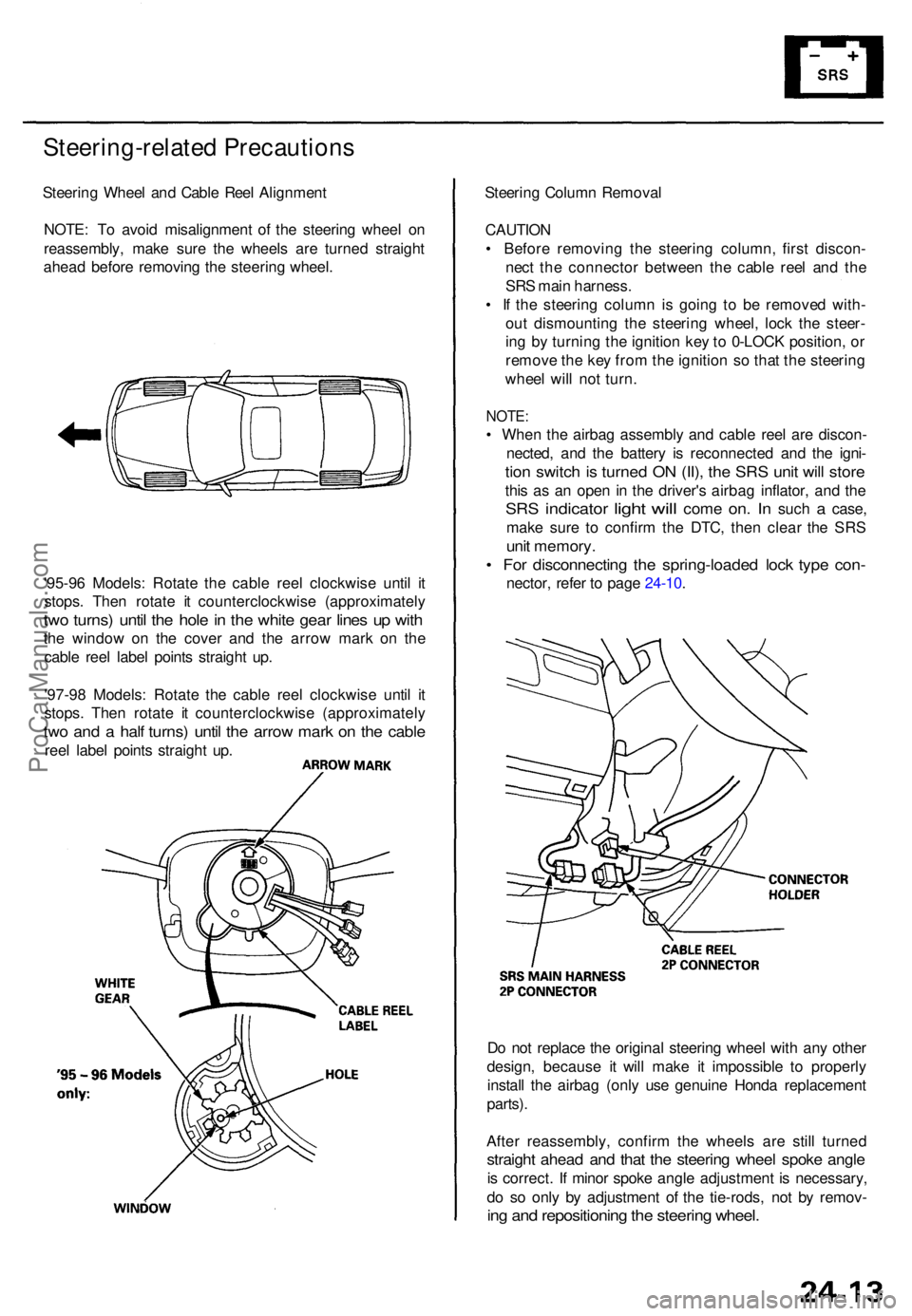
'95-9 6 Models : Rotat e th e cabl e ree l clockwis e unti l i t
stops . The n rotat e i t counterclockwis e (approximatel y
two turns ) unti l th e hol e in th e whit e gea r line s u p wit h
the windo w o n th e cove r an d th e arro w mar k o n th e
cabl e ree l labe l point s straigh t up .
'97-9 8 Models : Rotat e th e cabl e ree l clockwis e unti l i t
stops . The n rotat e i t counterclockwis e (approximatel y
two an d a hal f turns ) unti l th e arro w mar k o n th e cabl e
reel labe l point s straigh t up . Steerin
g Colum n Remova l
CAUTIO N
• Befor e removin g th e steerin g column , firs t discon -
nec t th e connecto r betwee n th e cabl e ree l an d th e
SR S mai n harness .
• I f th e steerin g colum n i s goin g t o b e remove d with -
ou t dismountin g th e steerin g wheel , loc k th e steer -
in g b y turnin g th e ignitio n ke y to 0-LOC K position , o r
remov e th e ke y fro m th e ignitio n s o tha t th e steerin g
whee l wil l no t turn .
NOTE :
• Whe n th e airba g assembl y an d cabl e ree l ar e discon -
nected , an d th e batter y i s reconnecte d an d th e igni -
tion switc h is turne d O N (II) , th e SR S uni t wil l stor e
this a s a n ope n i n th e driver' s airba g inflator , an d th e
SR S indicato r light will com e on. I n suc h a case ,
mak e sur e t o confir m th e DTC , the n clea r th e SR S
unit memory .
• Fo r disconnectin g th e spring-loade d loc k typ e con -
nector , refe r t o pag e 24-10 .
D o no t replac e th e origina l steerin g whee l wit h an y othe r
design , becaus e i t wil l mak e i t impossibl e t o properly
instal l th e airba g (onl y us e genuin e Hond a replacemen t
parts) .
Afte r reassembly , confir m th e wheel s ar e stil l turne d
straight ahea d an d tha t th e steerin g whee l spok e angl e
is correct . I f mino r spok e angl e adjustment is necessary ,
d o s o onl y b y adjustmen t o f th e tie-rods , no t b y remov -
ing an d repositionin g th e steerin g wheel .
ProCarManuals.com