1995 ACURA TL steering wheel
[x] Cancel search: steering wheelPage 660 of 1771
Airbag
Replacement (cont'd)
CAUTION: Be sure to install the SRS wiring so that it is
not pinched or interfering with other parts.
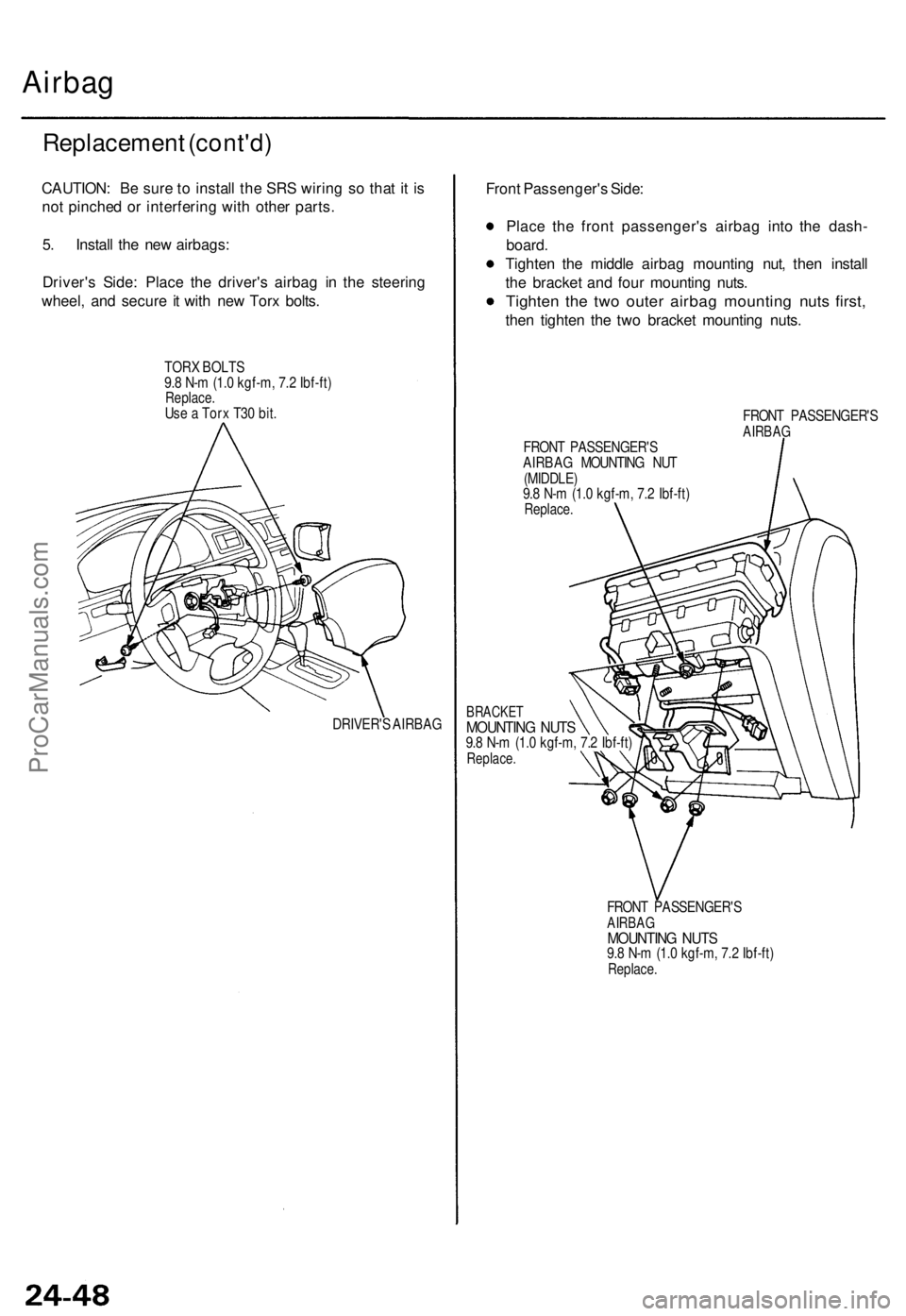
5. Install the new airbags:
Driver's Side: Place the driver's airbag in the steering
wheel, and secure it with new Torx bolts.
TORX BOLTS
9.8 N-m (1.0 kgf-m, 7.2 Ibf-ft)
Replace.
Use a Torx T30 bit.
DRIVER'S AIRBAG
Front Passenger's Side:
Place the front passenger's airbag into the dash-
board.
Tighten the middle airbag mounting nut, then install
the bracket and four mounting nuts.
Tighten the two outer airbag mounting nuts first,
then tighten the two bracket mounting nuts.
FRONT PASSENGER'S
AIRBAG
FRONT PASSENGER'S
AIRBAG MOUNTING NUT
(MIDDLE)
9.8 N-m (1.0 kgf-m, 7.2 Ibf-ft)
Replace.
BRACKET
MOUNTING NUTS
9.8 N-m (1.0 kgf-m, 7.2 Ibf-ft)
Replace.
FRONT PASSENGER'S
AIRBAG
MOUNTING NUTS
9.8 N-m (1.0 kgf-m, 7.2 Ibf-ft)
Replace.ProCarManuals.com
Page 661 of 1771
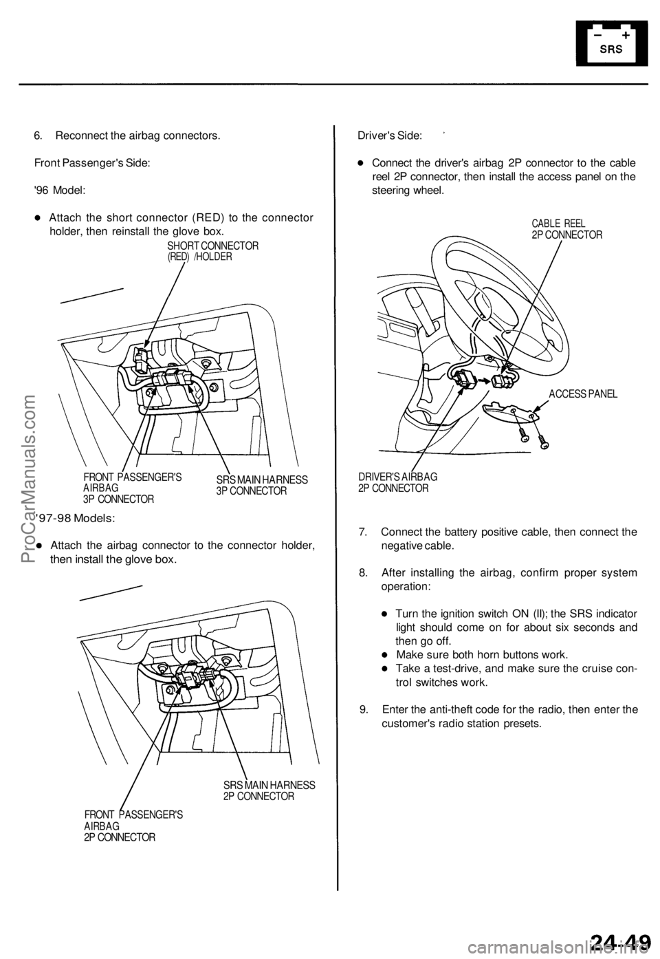
6. Reconnect the airbag connectors.
Front Passenger's Side:
'96 Model:
Attach the short connector (RED) to the connector
holder, then reinstall the glove box.
SHORT CONNECTOR
(RED) /HOLDER
FRONT PASSENGER'S
AIRBAG
3P CONNECTOR
SRS MAIN HARNESS
3P CONNECTOR
'97-98 Models:
Attach the airbag connector to the connector holder,
then install the glove box.
SRS MAIN HARNESS
2P CONNECTOR
FRONT PASSENGER'S
AIRBAG
2P CONNECTOR
Driver's Side:
Connect the driver's airbag 2P connector to the cable
reel 2P connector, then install the access panel on the
steering wheel.
CABLE REEL
2P CONNECTOR
ACCESS PANEL
DRIVER'S AIRBAG
2P CONNECTOR
7. Connect the battery positive cable, then connect the
negative cable.
8. After installing the airbag, confirm proper system
operation:
Turn the ignition switch ON (II); the SRS indicator
light should come on for about six seconds and
then go off.
Make sure both horn buttons work.
Take a test-drive, and make sure the cruise con-
trol switches work.
9. Enter the anti-theft code for the radio, then enter the
customer's radio station presets.ProCarManuals.com
Page 665 of 1771
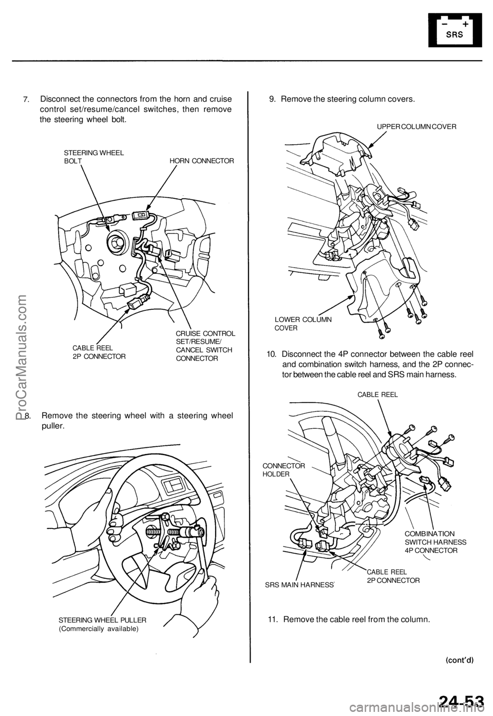
7.
Disconnect the connectors from the horn and cruise
control set/resume/cancel switches, then remove
the steering wheel bolt.
STEERING WHEEL
BOLT
HORN CONNECTOR
CABLE REEL
2P CONNECTOR
CRUISE CONTROL
SET/RESUME/
CANCEL SWITCH
CONNECTOR
8.
Remove the steering wheel with a steering wheel
puller.
STEERING WHEEL PULLER
(Commercially available)
9. Remove the steering column covers.
UPPER COLUMN COVER
LOWER COLUMN
COVER
10. Disconnect the 4P connector between the cable reel
and combination switch harness, and the 2P connec-
tor between the cable reel and SRS main harness.
CABLE REEL
CONNECTOR
HOLDER
COMBINATION
SWITCH HARNESS
4P CONNECTOR
SRS MAIN HARNESS
CABLE REEL
2P CONNECTOR
11. Remove the cable reel from the column.ProCarManuals.com
Page 666 of 1771
Cable Reel
Replacement (cont'd)
12.
NOTE:
Before installing the steering wheel, the front
wheels should be aligned straight ahead.
Be sure to install the harness wires so that they
are not pinched or interfering with other parts.
After reassembly, confirm that the wheels are
still turned straight ahead and that the steering
wheel spoke angle is correct (road test). If minor
spoke angle adjustment is necessary, do so only
by adjusting the tie-rods, not by removing and
repositioning the steering wheel.
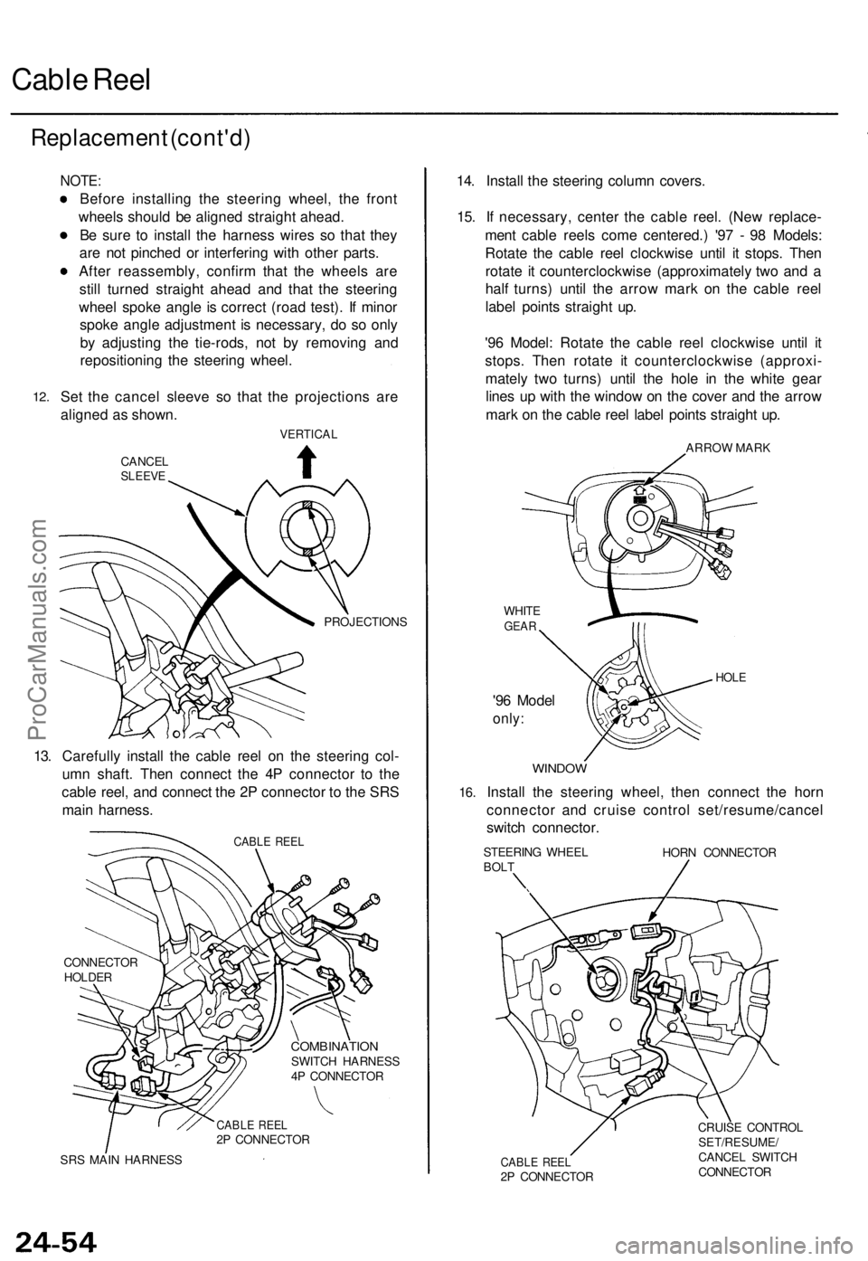
Set the cancel sleeve so that the projections are
aligned as shown.
VERTICAL
CANCEL
SLEEVE
PROJECTIONS
13. Carefully install the cable reel on the steering col-
umn shaft. Then connect the 4P connector to the
cable reel, and connect the 2P connector to the SRS
main harness.
CABLE REEL
CONNECTOR
HOLDER
COMBINATION
SWITCH HARNESS
4P CONNECTOR
CABLE REEL
2P CONNECTOR
SRS MAIN HARNESS
14. Install the steering column covers.
15. If necessary, center the cable reel. (New replace-
ment cable reels come centered.) '97 - 98 Models:
Rotate the cable reel clockwise until it stops. Then
rotate it counterclockwise (approximately two and a
half turns) until the arrow mark on the cable reel
label points straight up.
'96 Model: Rotate the cable reel clockwise until it
stops. Then rotate it counterclockwise (approxi-
mately two turns) until the hole in the white gear
lines up with the window on the cover and the arrow
mark on the cable reel label points straight up.
ARROW MARK
WHITE
GEAR
'96 Model
only:
HOLE
16.
WINDOW
Install the steering wheel, then connect the horn
connector and cruise control set/resume/cancel
switch connector.
STEERING WHEEL
BOLT
HORN CONNECTOR
CABLE REEL
2P CONNECTOR
CRUISE CONTROL
SET/RESUME/
CANCEL SWITCH
CONNECTORProCarManuals.com
Page 667 of 1771
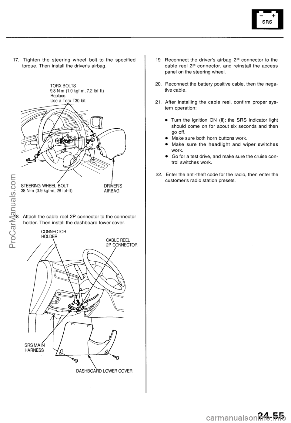
17. Tighten the steering wheel bolt to the specified
torque. Then install the driver's airbag.
TORX BOLTS
9.8 N-m (1.0 kgf-m, 7.2 Ibf-ft)
Replace.
Use a Torx T30 bit.
STEERING WHEEL BOLT
38 N-m (3.9 kgf-m, 28 Ibf-ft)
DRIVER'S
AIRBAG
18. Attach the cable reel 2P connector to the connector
holder. Then install the dashboard lower cover.
CONNECTOR
HOLDER
CABLE REEL
2P CONNECTOR
SRS
MAIN
HARNESS
DASHBOARD LOWER COVER
19. Reconnect the driver's airbag 2P connector to the
cable reel 2P connector, and reinstall the access
panel on the steering wheel.
20. Reconnect the battery positive cable, then the nega-
tive cable.
21. After installing the cable reel, confirm proper sys-
tem operation:
Turn the ignition ON (II); the SRS indicator light
should come on for about six seconds and then
go
off.
Make sure both horn buttons work.
Make sure the headlight and wiper switches
work.
Go for a test drive, and make sure the cruise con-
trol switches work.
22. Enter the anti-theft code for the radio, then enter the
customer's radio station presets.ProCarManuals.com
Page 669 of 1771
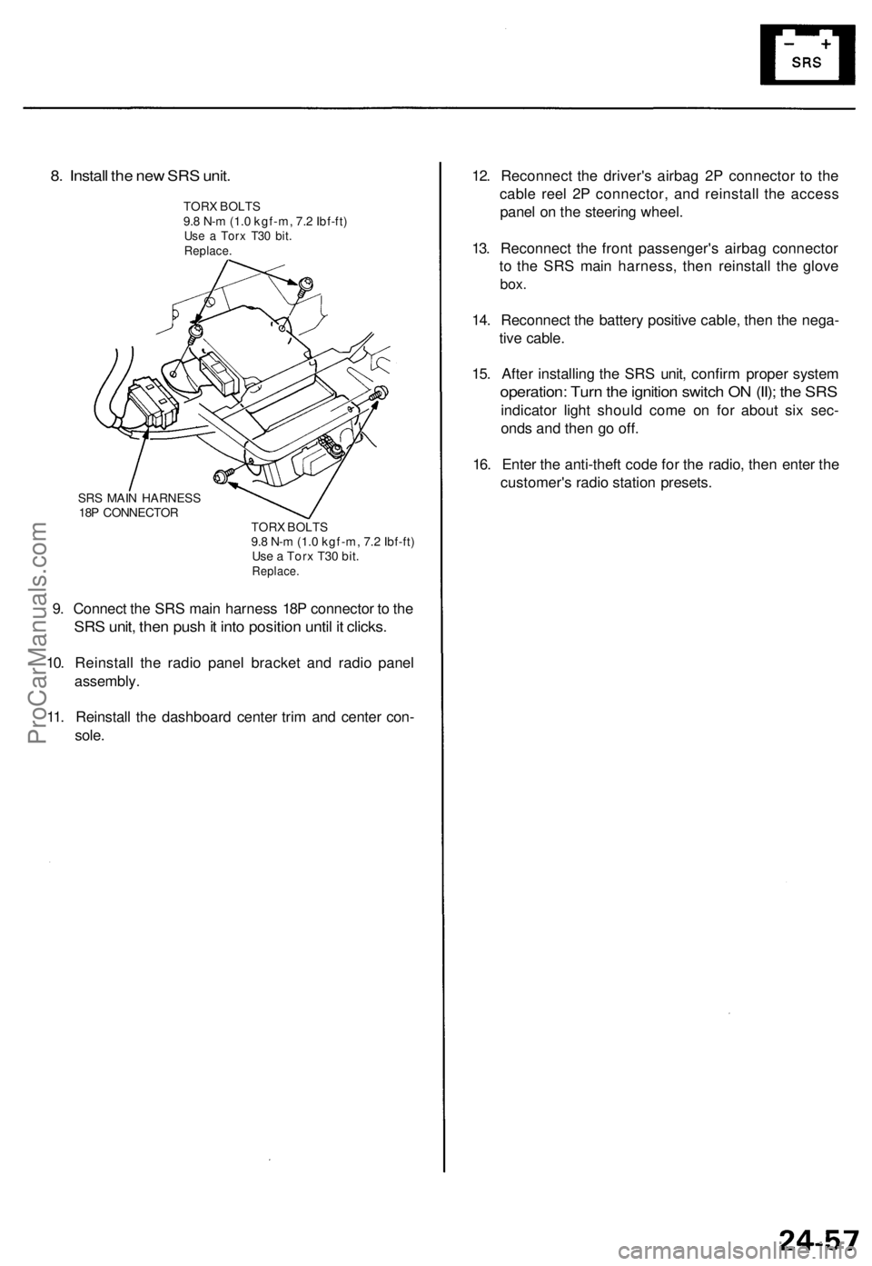
8. Install the new SRS unit.
TORX BOLTS
9.8 N-m (1.0 kgf-m, 7.2 Ibf-ft)
Use a Torx T30 bit.
Replace.
SRS MAIN HARNESS
18P CONNECTOR
TORX BOLTS
9.8 N-m (1.0 kgf-m, 7.2 Ibf-ft)
Use a Torx T30 bit.
Replace.
9. Connect the SRS main harness 18P connector to the
SRS unit, then push it into position until it clicks.
10. Reinstall the radio panel bracket and radio panel
assembly.
11. Reinstall the dashboard center trim and center con-
sole.
12. Reconnect the driver's airbag 2P connector to the
cable reel 2P connector, and reinstall the access
panel on the steering wheel.
13. Reconnect the front passenger's airbag connector
to the SRS main harness, then reinstall the glove
box.
14. Reconnect the battery positive cable, then the nega-
tive cable.
15. After installing the SRS unit, confirm proper system
operation: Turn the ignition switch ON (II); the SRS
indicator light should come on for about six sec-
onds and then go off.
16. Enter the anti-theft code for the radio, then enter the
customer's radio station presets.ProCarManuals.com
Page 682 of 1771
Warning/Caution Label Locations
(cont'd)
D: DRIVER INFORMATION (SUNVISOR)
Canada model (98 model)
CAUTION
TO AVOID SERIOUS INJURY:
FOR MAXIMUM SAFETY PROTECTION IN ALL TYPES OF
CRASHES, YOU MUST ALWAYS WEAR YOUR SAFETY
BELT.
DO NOT INSTALL REARWARD FACING CHILD SEATS IN
ANY FRONT PASSENGER SEAT POSITION.
DO NOT SIT OR LEAN UNNECESSARILY CLOSE TO THE
AIRBAG.
DO NOT PLACE ANY OBJECTS OVER THE AIRBAG OR
BETWEEN THE AIRBAG AND YOURSELF.
SEE THE OWNER'S MANUAL FOR FURTHER INFORMA-
TION AND EXPLANATIONS.
THE SRS MUST BE INSPECTED TEN YEARS AFTER IT IS
INSTALLED.
THE DATE OF INSTALLATION IS SHOWN OF THE DRIV-
ER'S DOORJAMB.
E: ASSISTANT INFORMATION
U.S. model
AIRBAG SEE OTHER SIDE.
U.S. model (98 model)
AIRBAG WARNING
FLIP VISOR OVER
F: STEERING COLUMN NOTICE
NOTICE
TO PREVENT SRS DAMAGE, REMOVE STEERING WHEEL
BEFORE REMOVING STEERING SHAFT CONNECTING
BOLT.
G: MONITOR NOTICE
NOTICE
• NO SERVICEABLE PARTS INSIDE.
• REFER TO SERVICE MANUAL FOR DETAILED INSTRUC-
TIONS.
H: SRS CONSOLE/GLOVE BOX INFORMATION
Canada model (95 - 97 model)
AIRBAG INFORMATION
SUPPLEMENTAL RESTRAINT SYSTEM (SRS)
• THE SRS MUST BE INSPECTED TEN YEARS AFTER IT IS
INSTALLED. THE DATE OF INSTALLATION IS SHOWN
ON THE CERTIFICATION PLATE, LOCATED ON THE
DRIVER'S DOORJAMB.
• DIAGNOSTIC CHECKS AND REPLACEMENT OF SRS
COMPONENTS MUST BE DONE BY AN AUTHORIZED
DEALER.
• SEE YOUR OWNER'S MANUAL FOR ADDITIONAL SRS
INFORMATION.
I: FRONT SEAT PASSENGER AIRBAG MODULE DANGER
DANGER
EXPLOSIVE/FLAMMABLE
CONTACT WITH ACID, WATER OR HEAVY METALS SUCH
AS COPPER, LEAD OR MERCURY MAY PRODUCE HARM-
FUL AND IRRITATING GASES OR EXPLOSIVE COM-
POUNDS. STORAGE TEMPERATURES MUST NOT EXCEED
200 F (100°C). FOR PROPER HANDLING, STORAGE AND
DISPOSAL PROCEDURES REFER TO SERVICE MANUAL,
SRS SUPPLEMENT.
POISON
CONTAINS POISONOUS SODIUM AZIDE AND POTASSIUM
NITRATE.
FIRST AID
IF CONTENTS ARE SWALLOWED, INDUCE VOMITING.
FOR EYE CONTACT, FLUSH EYES WITH WATER FOR 15
MINUTES. IF GASES (FROM ACID OR WATER CONTACT)
ARE INHALED, SEEK FRESH AIR. IN EVERY CASE, GET
PROMPT MEDICAL ATTENTION.
KEEP OUT OF REACH OF CHILDREN.
WARNING
THE AIRBAG INFLATOR IS EXPLOSIVE AND, IF ACCIDEN-
TALLY DEPLOYED, CAN SERIOUSLY HURT OR KILL YOU.
• DO NOT USE ELECTRICAL TEST EQUIPMENT OR PROB-
ING DEVICES. THEY CAN CAUSE ACCIDENTAL DEPLOY-
MENT.
• NO SERVICEABLE PARTS INSIDE. DO NOT DISASSEM-
BLE.
• PLACE AIRBAG UPRIGHT WHEN REMOVED.
• FOLLOW SERVICE MANUAL INSTRUCTIONS CAREFULLY.
J: PASSENGER AIRBAG CAUTION
U.S. model (98 model)
WARNING
CHILDREN CAN BE KILLED OR INJURED BY A PASSENGER
AIRBAG.
THE BACK SEAT IS THE SAFEST PLACE FOR CHILDREN
AGES 12 AND UNDER. MAKE SURE ALL CHILDREN USE
SEAT BELTS OR CHILD SEATS.
K: SRS WARNING (HOOD)
SUPPLEMENTAL RESTRAINT SYSTEM (SRS)
THIS VEHICLE IS EQUIPPED WITH DRIVER AND FRONT
SEAT PASSENGER AIRBAGS.
ALL SRS ELECTRICAL WIRING AND CONNECTORS ARE
COLORED YELLOW.
TAMPERING WITH, DISCONNECTING OR USING ELECTRI-
CAL TEST EQUIPMENT ON THE SRS WIRING CAN MAKE
THE SYSTEM INOPERATIVE OR CAUSE ACCIDENTAL FIR-
ING OF THE INFLATOR.
WARNING
THE AIRBAG INFLATOR IS EXPLOSIVE AND, IF ACCIDEN-
TALLY DEPLOYED, CAN SERIOUSLY HURT YOU. FOLLOW
SERVICE MANUAL INSTRUCTIONS CAREFULLY.ProCarManuals.com
Page 1144 of 1771
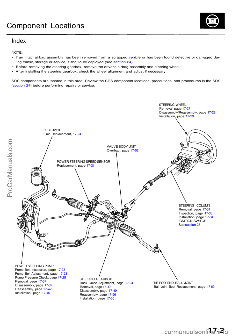
Component Location s
Index
NOTE :
• I f a n intac t airba g assembl y ha s bee n remove d fro m a scrappe d vehicl e o r ha s bee n foun d defectiv e o r damage d dur -
in g transit , storag e o r service , i t shoul d b e deploye d (se e sectio n 24 ).
• Befor e removin g th e steerin g gearbox , remov e th e driver' s airba g assembl y an d steerin g wheel .
• Afte r installin g th e steerin g gearbox , chec k th e whee l alignmen t an d adjus t i f necessary .
SR S component s ar e locate d in thi s area . Revie w th e SR S componen t locations , precautions , an d procedure s in th e SR S
( sectio n 24 ) befor e performin g repair s o r service .
STEERIN G WHEE LRemoval , pag e 17-2 7
Disassembly/Reassembly , pag e 17-2 8
Installation , pag e 17-2 9
RESERVOI RFluid Replacement , 17-2 4
VALVE BOD Y UNI T
Overhaul , pag e 17-5 2
POWE R STEERIN G SPEE D SENSO R
Replacement , pag e 17-2 1
STEERING COLUM N
Removal , pag e 17-3 1
Inspection , pag e 17-3 3
Installation , pag e 17-3 4IGNITIO N SWITC HSee sectio n 2 3
POWE R STEERIN G PUM P
Pum p Bel t Inspection , pag e 17-2 3
Pum p Bel t Adjustment , pag e 17-2 3
Pum p Pressur e Check , pag e 17-2 5
Removal , pag e 17-3 7
Disassembly , pag e 17-3 7
Reassembly , pag e 17-4 2
Installation , pag e 17-4 6
STEERIN G GEARBO XRack Guid e Adjustment , pag e 17-2 4
Removal , pag e 17-4 7
Disassembly , pag e 17-4 9
Reassembly , pag e 17-5 6
Installation , pag e 17-6 6 TIE-RO
D EN D BAL L JOIN T
Bal l Join t Boo t Replacement , pag e 17-6 9
ProCarManuals.com