1995 ACURA TL buttons
[x] Cancel search: buttonsPage 43 of 1771
Engine Removal/Installatio n
Removal
Make sur e jack s an d safet y stand s ar e place d properl y
an d hois t bracket s ar e attache d to th e correc t position s
o n th e engine .
Mak e sur e th e ca r wil l no t rol l of f stand s an d fal l
whil e yo u ar e workin g unde r it .
CAUTION :
Us e fende r cover s t o avoi d damagin g painte d sur -
faces .
Unplu g th e wirin g connector s carefull y whil e holdin g
th e connecto r portio n t o avoi d damage .
Mar k al l wirin g an d hose s t o avoi d misconnection .
Also , b e sur e tha t the y d o no t contac t othe r wirin g
o r hose s o r interfer e wit h othe r parts .
1 . Mov e th e fron t passenger' s sea t forward .
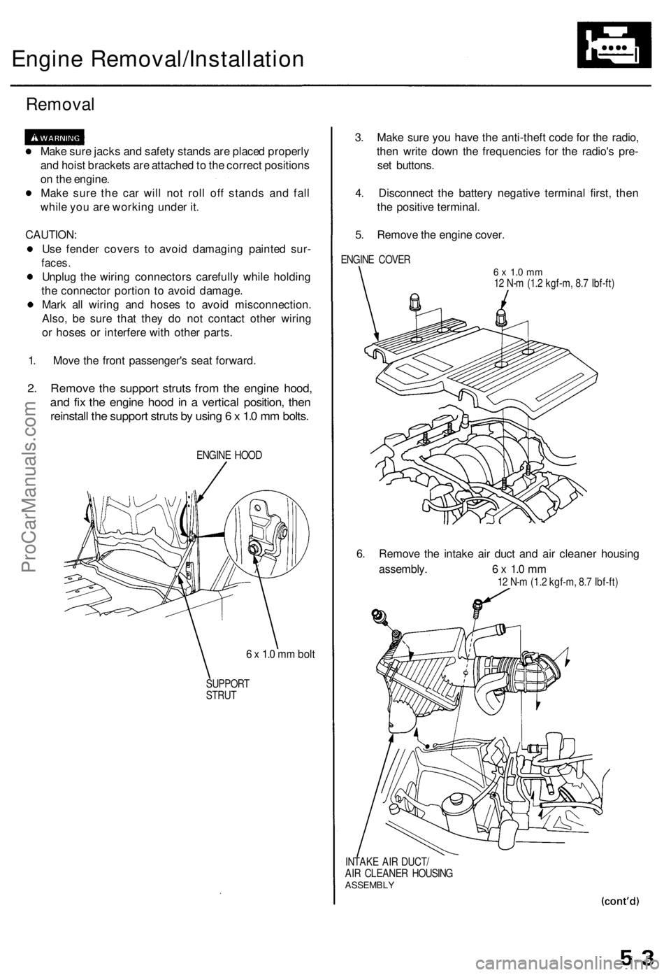
2. Remov e th e suppor t strut s fro m th e engin e hood ,
and fi x th e engin e hoo d in a vertica l position , the n
reinstal l th e suppor t strut s b y usin g 6 x 1. 0 m m bolts .
ENGIN E HOO D
6 x 1. 0 m m bol t
SUPPOR T
STRU T
3. Mak e sur e yo u hav e th e anti-thef t cod e fo r th e radio ,
the n writ e dow n th e frequencie s fo r th e radio' s pre -
se t buttons .
4 . Disconnec t th e batter y negativ e termina l first , the n
th e positiv e terminal .
5 . Remov e th e engin e cover .
ENGIN E COVE R6 x 1. 0 m m12 N- m (1. 2 kgf-m , 8. 7 Ibf-ft )
6. Remov e th e intak e ai r duc t an d ai r cleane r housin g
assembly . 6 x 1. 0 m m
12 N- m (1.2 kgf-m , 8. 7 Ibf-ft )
INTAK E AI R DUCT /
AI R CLEANE R HOUSIN G
ASSEMBL Y
ProCarManuals.com
Page 63 of 1771
Timing Bel t
Remova l
NOTE:
Replac e th e timin g bel t a t 105,00 0 mile s (168,00 0 km )
accordin g t o th e maintenanc e schedul e (norma l con -
ditions/sever e conditions) .
I f th e vehicl e is regularl y drive n i n on e o r mor e o f th e
followin g conditions , replac e th e timin g bel t a t 60,00 0
mile s (U.S.A. ) 100,00 0 k m (Canada) .
I n ver y hig h temperature s (ove r 110°F , 43°C )
I n ver y lo w temperature s (unde r -20°F , -29°C )
Tur n th e crankshaf t pulle y s o th e No . 1 pisto n i s a t
to p dea d cente r (TDC ) befor e removin g th e bel t (se e
pag e 6-8 ).
Inspec t th e wate r pum p befor e installin g th e timin g
bel t (se e pag e 10-10 ).
1 . Mak e sur e yo u hav e th e anti-thef t cod e fo r th e radio ,
the n writ e dow n th e frequencie s fo r th e radio' s prese t
buttons .
2. Disconnec t th e negativ e termina l fro m th e battery .
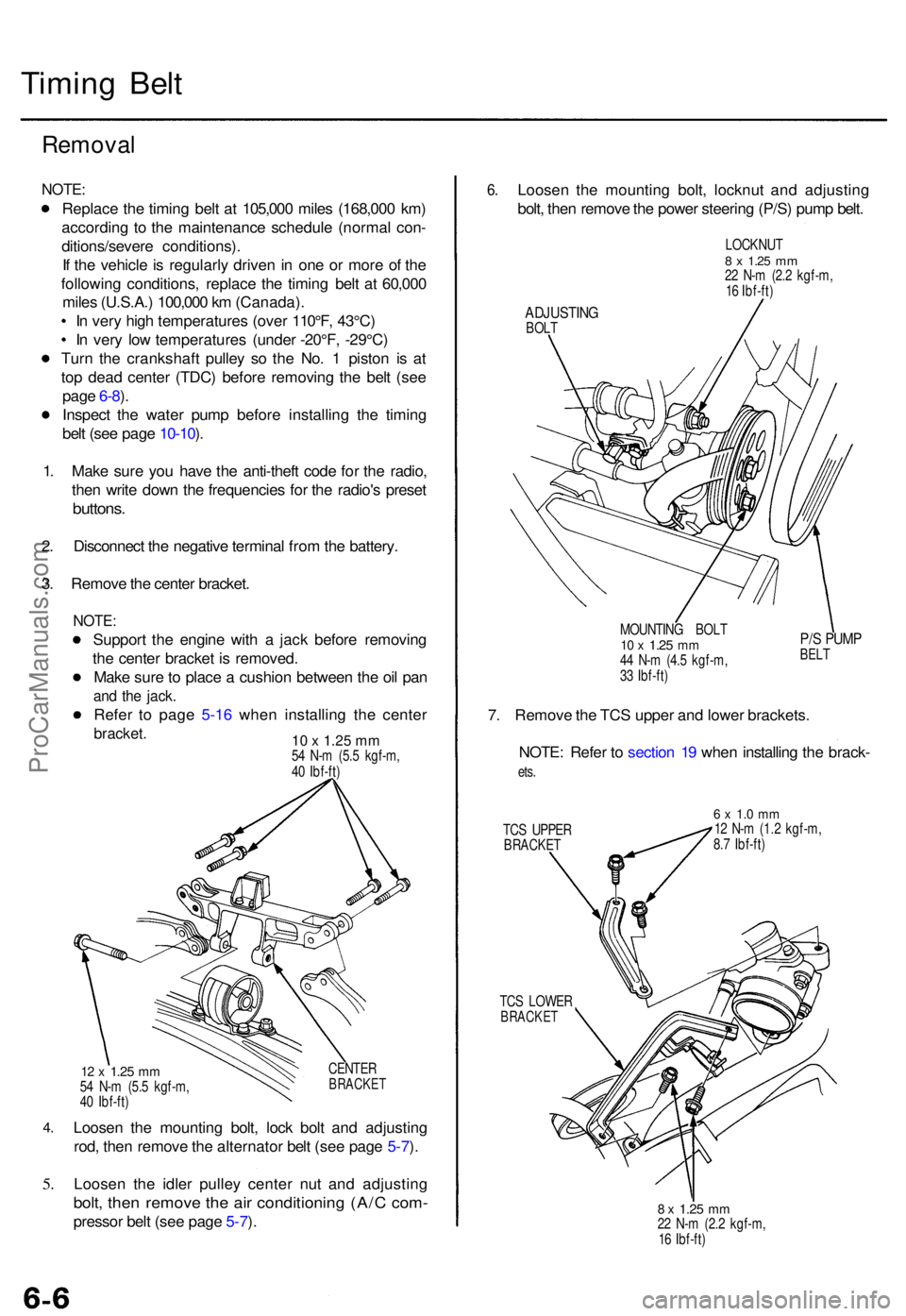
3 . Remov e th e cente r bracket .
NOTE:
Suppor t th e engin e wit h a jac k befor e removin g
th e cente r bracke t i s removed .
Mak e sur e to plac e a cushio n betwee n th e oi l pa n
and th e jack .
Refer t o pag e 5-1 6 whe n installin g th e cente r
bracket. 10 x 1.25 mm54 N- m (5. 5 kgf-m ,
4 0 Ibf-ft )
4.
5.
CENTE RBRACKE T12 x 1.2 5 mm54 N- m (5. 5 kgf-m ,
4 0 Ibf-ft )
Loose n th e mountin g bolt , loc k bol t an d adjustin g
rod , the n remov e th e alternato r bel t (se e pag e 5-7 ).
Loose n th e idle r pulle y cente r nu t an d adjustin g
bolt, the n remov e th e ai r conditionin g (A/ C com -
presso r bel t (se e pag e 5-7 ).
6 .Loose n th e mountin g bolt , locknu t an d adjustin g
bolt , the n remov e th e powe r steerin g (P/S ) pum p belt .
LOCKNU T8 x 1.2 5 mm22 N- m (2. 2 kgf-m ,
1 6 Ibf-ft )
ADJUSTIN GBOLT
MOUNTING BOL T
10 x 1.2 5 mm44 N- m (4. 5 kgf-m ,
3 3 Ibf-ft )
P/S PUM PBELT
7. Remov e th e TC S uppe r an d lowe r brackets .
NOTE : Refe r t o sectio n 1 9 whe n installin g th e brack -
ets.
TC S UPPE RBRACKE T
6 x 1. 0 m m12 N- m (1. 2 kgf-m ,
8. 7 Ibf-ft )
TC S LOWE R
BRACKE T
8 x 1.2 5 mm22 N- m (2. 2 kgf-m ,
1 6 Ibf-ft )
ProCarManuals.com
Page 73 of 1771
Cylinder Head s
Remova l
Engine remova l i s no t require d fo r thi s procedure .
Mak e sur e jack s an d safet y stand s ar e
place d properl y an d hois t bracket s ar e attache d th e t o
correc t position s o n th e engine .
CAUTION :
Us e fende r cover s t o avoi d damagin g painte d sur -
faces .
Unplu g th e wirin g connector s carefull y whil e holdin g
th e connecto r portio n to avoi d damage .
T o avoi d damagin g th e cylinde r head , wai t unti l th e
engin e coolan t temperatur e drop s belo w 100° F (38°C )
befor e loosenin g th e retainin g bolts .
NOTE :
Mark al l wirin g an d hose s t o avoi d misconnection .
Also , b e sur e tha t the y d o no t contac t othe r wirin g o r
hoses , o r interfer e wit h othe r parts .
Inspec t th e timin g bel t befor e removin g th e cylinde r
head .
Tur n th e crankshaf t pulle y s o tha t th e No . 1 pisto n i s
a t to p dea d cente r (se e pag e 6-10 ).
1 . Mak e sur e yo u hav e th e anti-thef t cod e fo r th e
radio , the n writ e dow n th e frequencie s fo r th e
radio' s prese t buttons .
2 . Disconnec t th e batter y negativ e termina l first , the n
the positiv e terminal .
3. Drai n th e engin e coolan t (se e pag e 10-5 ).
4 . Remov e th e engin e cove r (se e pag e 5-3 ).
5 . Remov e th e intak e ai r duc t an d ai r cleane r housin g
assembl y (se e pag e 5-3 ).
6 . Remov e th e throttl e cove r (se e pag e 5-4 ).
7 . Remov e th e throttl e cabl e an d cruis e contro l cabl e
b y loosenin g th e locknuts , the n sli p th e cabl e end s
ou t o f th e accelerato r linkag e (se e pag e 5-4 ).
NOTE :
Take car e no t t o ben d a cabl e whe n removin g it .
Alway s replac e an y kinke d cabl e wit h a ne w one .
Adjus t th e throttl e cabl e whe n installin g (se e
sectio n 11 ).
Adjus t th e cruis e contro l cabl e whe n installin g
(se e sectio n 23 ). 8
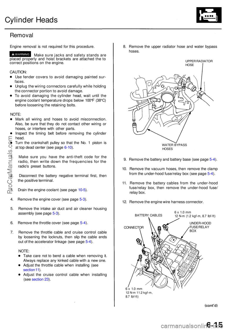
. Remov e th e uppe r radiato r hos e an d wate r bypas s
hoses.
UPPER RADIATO RHOSE
WATE R BYPAS SHOSES
9. Remov e th e batter y an d batter y bas e (se e pag e 5-4 ).
10 . Remov e th e vacuu m hoses , the n remov e th e clam p
fro m th e under-hoo d fuse/rela y bo x (se e pag e 5-4 ).
11 . Remov e th e batter y cable s fro m th e under-hoo d
fuse/rela y box , the n remov e th e under-hoo d fuse /
rela y box .
12 . Remov e th e engin e wir e harnes s connector .
BATTERY CABLE S
CONNECTO R
6 x 1. 0 m m12 N- m (1. 2 kgf-m , 8. 7 Ibf-ft )
UNDER-HOO DFUSE/RELAYBOX
6 x 1. 0 m m12 N- m 11. 2 kgf-m ,8.7 Ibf-ft )
ProCarManuals.com
Page 144 of 1771
Engine Coolan t Refillin g an d Bleedin g
CAUTION : Whe n pourin g engin e coolant , b e sur e t o
shu t th e rela y bo x li d an d no t t o le t coolan t spil l o n th e
electrica l part s o r th e paint . I f an y coolan t spills , rins e it
of f immediately .
NOTE:
Perfor m thi s procedur e whe n th e engin e is cool .
Befor e replacin g th e coolant , tur n th e ignitio n O N (II) ,
slowl y tur n th e climat e contro l temperatur e kno b t o
90 ° an d tur n of f th e ignition . Thi s wil l allo w th e
coolan t i n th e heate r t o drai n ou t wit h th e res t o f th e
system .
1 . Mak e sur e yo u hav e th e anti-thef t cod e fo r th e radio ,
the n writ e dow n th e frequencie s fo r th e radio' s pre -
se t buttons .
2 . Disconnec t th e batter y negativ e termina l first , the n
th e positiv e terminal , the n remov e th e batter y an d
batter y bas e (se e pag e 5-4 ).
3 . Whe n th e radiato r i s cool , remov e th e radiato r cap .
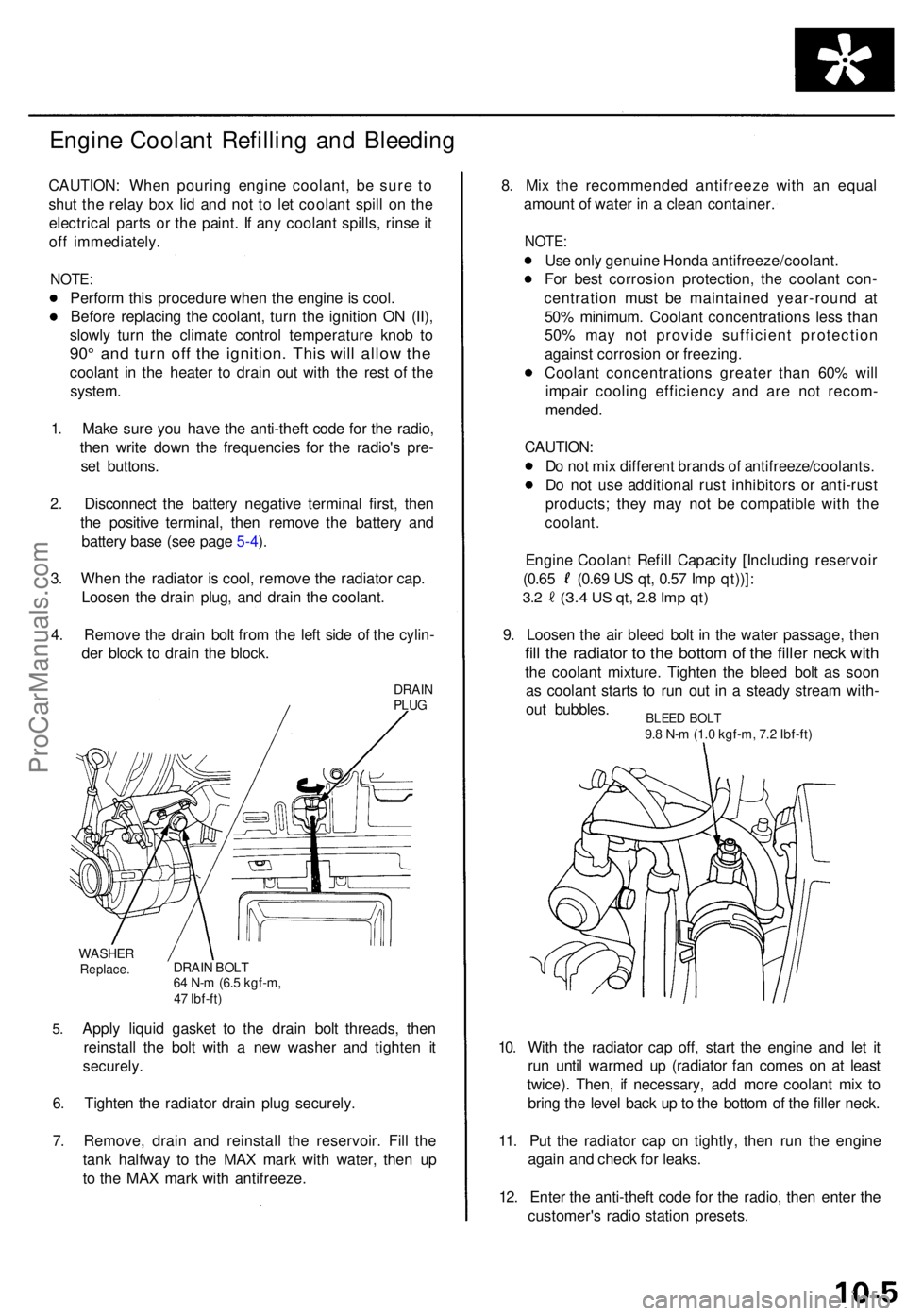
Loose n th e drai n plug , an d drai n th e coolant .
4 . Remov e th e drai n bol t fro m th e lef t sid e o f th e cylin -
de r bloc k t o drai n th e block .
DRAINPLUG
5.
WASHE RReplace .DRAIN BOL T64 N- m (6. 5 kgf-m ,
4 7 Ibf-ft )
Apply liqui d gaske t t o th e drai n bol t threads , the n
reinstal l th e bol t wit h a ne w washe r an d tighte n i t
securely .
6. Tighte n th e radiato r drai n plu g securely .
7 . Remove , drai n an d reinstal l th e reservoir . Fil l th e
tan k halfwa y t o th e MA X mar k wit h water , the n u p
t o th e MA X mar k wit h antifreeze . 8
. Mi x th e recommende d antifreez e wit h a n equa l
amoun t o f wate r i n a clea n container .
NOTE:
Use onl y genuin e Hond a antifreeze/coolant .
Fo r bes t corrosio n protection , th e coolan t con -
centratio n mus t b e maintaine d year-roun d a t
50 % minimum . Coolan t concentration s les s tha n
50 % ma y no t provid e sufficien t protectio n
agains t corrosio n o r freezing .
Coolan t concentration s greate r tha n 60 % wil l
impai r coolin g efficienc y an d ar e no t recom -
mended .
CAUTION :
D o no t mi x differen t brand s o f antifreeze/coolants .
D o no t us e additiona l rus t inhibitor s o r anti-rus t
products ; the y ma y no t b e compatibl e wit h th e
coolant .
Engine Coolan t Refil l Capacit y [Includin g reservoi r
(0.65 (0.6 9 U S qt , 0.5 7 Im p qt))] :
3.2 (3. 4 US qt , 2. 8 Im p qt )
9. Loose n th e ai r blee d bol t i n th e wate r passage , the n
fill th e radiato r t o th e botto m o f th e fille r nec k wit h
the coolan t mixture . Tighte n th e blee d bol t a s soo n
a s coolan t start s t o ru n ou t i n a stead y strea m with -
ou t bubbles .
10 . Wit h th e radiato r ca p off , star t th e engin e an d le t i t
ru n unti l warme d u p (radiato r fa n come s o n a t leas t
twice) . Then , i f necessary , ad d mor e coolan t mi x t o
brin g th e leve l bac k u p to th e botto m o f th e fille r neck .
11 . Pu t th e radiato r cap on tightly , the n ru n th e engin e
agai n an d chec k fo r leaks .
12 . Ente r th e anti-thef t cod e fo r th e radio , the n ente r th e
customer' s radi o statio n presets .
BLEED BOL T9.8 N- m (1. 0 kgf-m , 7. 2 Ibf-ft )
ProCarManuals.com
Page 223 of 1771
Fuel Pressure
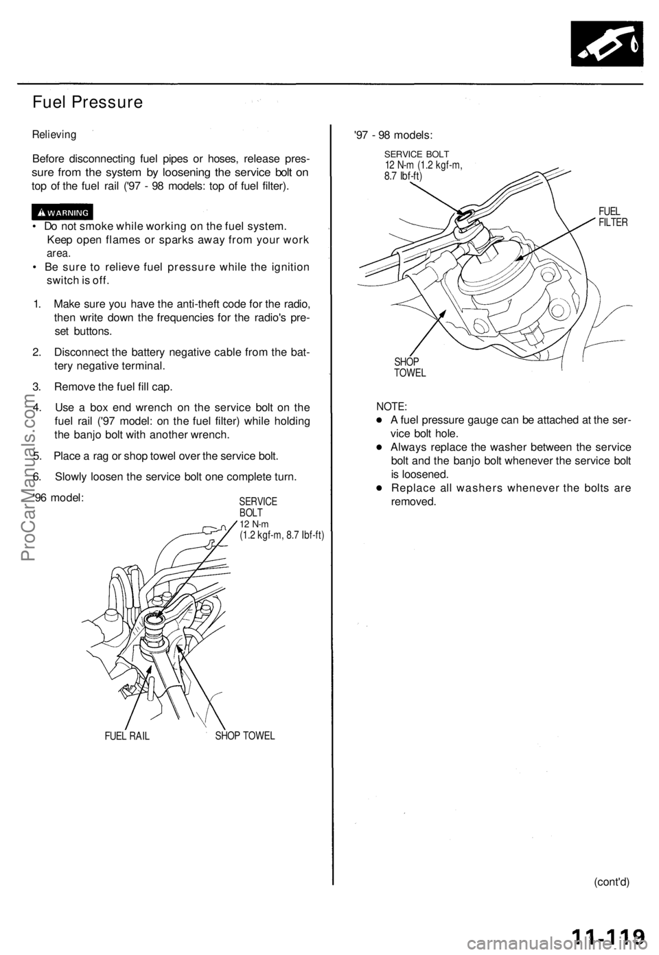
Relieving
Before disconnectin g fue l pipe s o r hoses , releas e pres -
sure fro m th e syste m b y loosenin g th e servic e bol t o n
top o f th e fue l rai l ('9 7 - 9 8 models : to p o f fue l filter) .
• D o no t smok e whil e workin g o n th e fue l system .
Kee p ope n flame s o r spark s awa y fro m you r wor k
area.
• B e sur e t o reliev e fue l pressur e whil e th e ignitio n
switc h is off .
1 . Mak e sur e yo u hav e th e anti-thef t cod e fo r th e radio ,
the n writ e dow n th e frequencie s fo r th e radio' s pre -
se t buttons .
2 . Disconnec t th e batter y negativ e cabl e fro m th e bat -
ter y negativ e terminal .
3 . Remov e th e fue l fil l cap .
4 . Us e a bo x en d wrenc h o n th e servic e bol t o n th e
fue l rai l ('9 7 model : o n th e fue l filter ) whil e holdin g
th e banj o bol t wit h anothe r wrench .
5 . Plac e a ra g o r sho p towe l ove r th e servic e bolt .
6 . Slowl y loose n th e servic e bol t on e complet e turn .
'9 6 model :
SERVIC EBOLT12 N- m(1.2 kgf-m , 8. 7 Ibf-ft )
FUE L RAI L SHO
P TOWE L
'97 - 9 8 models :
SERVICE BOL T12 N- m (1. 2 kgf-m ,8.7 Ibf-ft )
FUELFILTE R
SHOP
TOWE L
NOTE:
A fue l pressur e gaug e ca n b e attache d a t th e ser -
vic e bol t hole .
Alway s replac e th e washe r betwee n th e servic e
bol t an d th e banj o bol t wheneve r th e servic e bol t
i s loosened .
Replac e al l washer s wheneve r th e bolt s ar e
removed .
(cont'd)
ProCarManuals.com
Page 232 of 1771
Fuel Filte r
Replacemen t
• D o no t smok e whil e workin g o n fue l system .
Kee p ope n flam e awa y fro m you r wor k area .
• Whil e replacin g th e fue l filter , b e carefu l t o kee p a saf e
distanc e betwee n batter y terminal s an d an y tools .
Th e fue l filte r shoul d b e replace d wheneve r th e fue l pres -
sur e drop s belo w th e specifie d valu e [26 0 - 31 0 kP a
(2.6 5 - 3.1 5 kgf/cm
2, 37. 7 - 44. 8 psi ) wit h th e fue l pressur e
regulato r vacuu m hos e disconnecte d an d pinched ] afte r
makin g sur e tha t th e fue l pum p an d th e fue l pressur e
regulato r ar e OK .
1 . Mak e sur e yo u hav e th e anti-thef t cod e fo r th e radio ,
the n writ e dow n th e frequencie s fo r th e radio' s pre -
set buttons .
2. Disconnec t th e batter y negativ e cabl e fro m th e bat -
ter y negativ e terminal .
3 . Plac e a sho p towe l unde r an d aroun d th e fue l filter .
4 . Reliev e fue l pressur e (se e pag e 11-119 ).
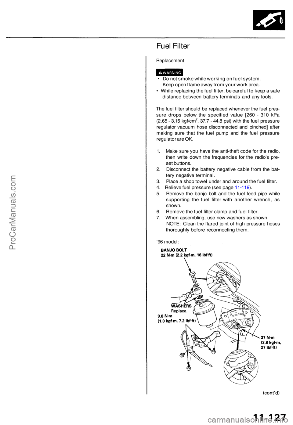
5 . Remov e th e banj o bol t an d th e fue l fee d pip e whil e
supportin g th e fue l filte r wit h anothe r wrench , a s
shown .
6 . Remov e th e fue l filte r clam p an d fue l filter .
7 . Whe n assembling , us e ne w washer s a s shown .
NOTE : Clea n th e flare d join t o f hig h pressur e hose s
thoroughl y befor e reconnectin g them .
'96 model :
ProCarManuals.com
Page 308 of 1771
PCM Reset Procedure
1. Make sure you have the anti-theft code for the radio, then write down the frequencies for the radio's preset buttons.
2. Turn the ignition switch OFF.
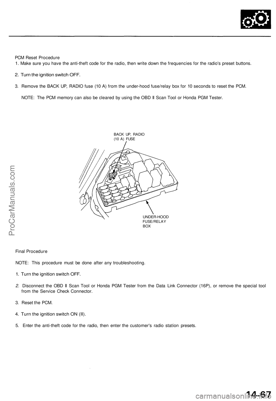
3. Remove the BACK UP, RADIO fuse (10 A) from the under-hood fuse/relay box for 10 seconds to reset the PCM.
NOTE: The PCM memory can also be cleared by using the OBD II Scan Tool or Honda PGM Tester.
BACK UP, RADIO
(10 A) FUSE
UNDER-HOOD
FUSE/RELAY
BOX
Final Procedure
NOTE: This procedure must be done after any troubleshooting.
1. Turn the ignition switch OFF.
2. Disconnect the OBD II Scan Tool or Honda PGM Tester from the Data Link Connector (16P), or remove the special tool
from the Service Check Connector.
3. Reset the PCM.
4. Turn the ignition switch ON (II).
5. Enter the anti-theft code for the radio, then enter the customer's radio station presets.ProCarManuals.com
Page 341 of 1771
Transmission
Removal
Make sur e lift s ar e place d properly , an d
hois t bracket s ar e attache d t o th e correc t positio n o n
th e engin e (se e sectio n 1 ).
CAUTION : Us e fende r cove r t o avoi d damagin g painte d
surfaces .
1. Befor e yo u disconnec t power , mak e sur e yo u hav e
th e anti-theft code fo r th e radio , the n writ e dow n
th e frequencie s fo r th e radio' s prese t buttons .
2 . Disconnec t th e batter y negativ e (- ) termina l fro m
th e battery , the n remov e th e positiv e (+ ) terminal .
3. Shif t th e transmissio n int o th e position .
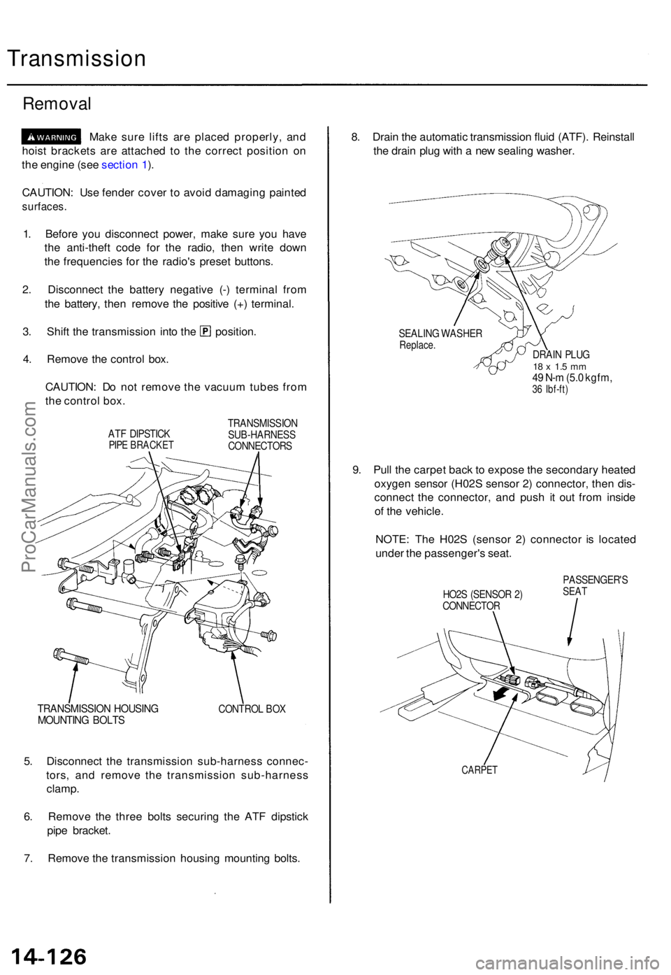
4 . Remov e th e contro l box .
CAUTION : D o no t remov e th e vacuu m tube s fro m
th e contro l box .
ATF DIPSTIC KPIPE BRACKE T
TRANSMISSIO N
SUB-HARNES S
CONNECTOR S
TRANSMISSIO N HOUSIN GMOUNTIN G BOLT SCONTRO L BO X
5. Disconnec t th e transmissio n sub-harnes s connec -
tors , an d remov e th e transmissio n sub-harnes s
clamp .
6 . Remov e th e thre e bolt s securin g th e AT F dipstic k
pip e bracket .
7 . Remov e th e transmissio n housin g mountin g bolts . 8
. Drai n th e automati c transmissio n flui d (ATF) . Reinstal l
th e drai n plu g wit h a ne w sealin g washer .
SEALIN G WASHE RReplace.DRAIN PLU G18 x 1. 5 m m49 N- m (5. 0 kgfm ,36 Ibf-ft )
9. Pul l th e carpe t bac k t o expos e th e secondar y heate d
oxyge n senso r (H02 S senso r 2 ) connector , the n dis -
connec t th e connector , an d pus h i t ou t fro m insid e
o f th e vehicle .
NOTE : Th e H02 S (senso r 2 ) connecto r i s locate d
unde r th e passenger' s seat .
HO2S (SENSO R 2 )
CONNECTO R PASSENGER'
SSEAT
CARPE T
ProCarManuals.com