Page 978 of 1771

4. Inspec t th e circui t o n th e TC M accordin g t o th e trou -
bleshootin g flowchar t wit h th e specia l tool s an d a
digita l multimete r a s shown .
How to us e th e Backprob e Se t
Connec t th e backprob e adapter s t o th e stackin g patc h
cords , an d connec t th e cord s t o a multimeter . Usin g
th e wir e insulatio n a s a guid e fo r th e contoure d ti p o f
the backprob e adapter , gentl y slid e th e ti p int o th e
connecto r fro m th e wir e sid e unti l i t come s i n contac t
with th e termina l en d o f th e wire .
BACKPROB E SE T07SAZ-001000 A
(tw o required )
BACKPROB EADAPTER
STACKIN GPATCH COR D
TCM
DIGITA L MULTIMETE R
(Commerciall y available )
KS-AHM-32-003 ,or equivalen t
TCM Rese t Procedur e
1 . Mak e sur e yo u hav e th e anti-thef t cod e fo r th e radio ,
the n writ e dow n th e frequencie s fo r th e radio' s pre -
set buttons .
2. Tur n th e ignitio n switc h OFF .
3 . Remov e th e No . 3 9 BAC K U P RADI O fus e (1 0 A )
fro m th e under-hoo d fuse/rela y bo x fo r 1 0 second s
t o rese t th e TCM .
NOTE : Th e TC M memor y canno t b e cleare d b y
usin g th e OB D II Sca n Too l o r Hond a PG M Tester ; b e
sur e to remov e th e BAC K U P RADI O fus e to rese t th e
TCM .
BACK U P RADI O
(1 0 A ) FUS E
UNDER-HOO D
FUSE/RELAYBOX
Fina l Procedur e
NOTE : Thi s procedur e mus t b e don e afte r an y trouble -
shooting.
1. Tur n th e ignitio n switc h OFF .
2 . Disconnec t th e OB D II Sca n Too l o r Hond a PG M
Teste r fro m th e Dat a Lin k Connector , o r remov e th e
specia l too l fro m th e Servic e Chec k Connector .
3. Rese t th e TCM .
4. Tur n th e ignitio n switc h O N (II) .
5 . Ente r th e anti-thef t cod e fo r th e radio , the n ente r th e
customer' s radi o statio n presets .
ProCarManuals.com
Page 1007 of 1771
Transmission
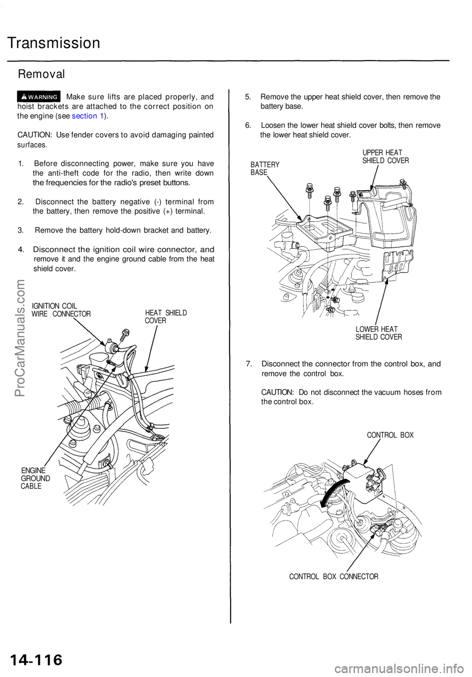
Removal
Make sur e lift s ar e place d properly , an d
hois t bracket s ar e attache d t o th e correc t positio n o n
th e engin e (se e sectio n 1 ).
CAUTION : Us e fende r cover s t o avoi d damagin g painte d
surfaces .
1. Befor e disconnectin g power , mak e sur e yo u hav e
th e anti-thef t cod e fo r th e radio , the n writ e dow n
the frequencie s fo r th e radio' s prese t buttons .
2. Disconnec t th e batter y negativ e (- ) termina l fro m
th e battery , the n remov e th e positiv e (+ ) terminal .
3 . Remov e th e batter y hold-dow n bracke t an d battery .
4. Disconnec t th e ignitio n coi l wir e connector , an d
remov e i t an d th e engin e groun d cabl e fro m th e hea t
shiel d cover .
IGNITIO N COI LWIRE CONNECTO R HEA
T SHIEL D
COVE R
ENGIN EGROUN DCABLE
5. Remov e th e uppe r hea t shiel d cover , the n remov e th e
batter y base .
6 . Loose n th e lowe r hea t shiel d cove r bolts , the n remov e
th e lowe r hea t shiel d cover .
BATTER YBASE
UPPE R HEA T
SHIEL D COVE R
LOWE R HEA T
SHIEL D COVE R
7. Disconnec t th e connecto r fro m th e contro l box , an d
remov e th e contro l box .
CAUTION : D o no t disconnec t th e vacuu m hose s fro m
th e contro l box .
CONTRO L BO X
CONTRO L BO X CONNECTO R
ProCarManuals.com
Page 1096 of 1771
Differential Assembl y
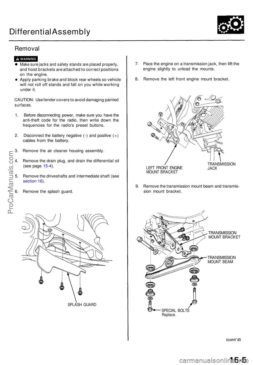
Removal
Make sur e jack s an d safet y stand s ar e place d properly ,
and hois t bracket s ar e attache d to correc t position s
o n th e engine .
• Apply parkin g brak e an d bloc k rea r wheel s s o vehicl e
wil l no t rol l of f stand s an d fal l o n yo u whil e workin g
unde r it .
CAUTION : Us e fende r cover s to avoi d damagin g painte d
surfaces .
1. Befor e disconnectin g power , mak e sur e yo u hav e th e
anti-thef t cod e fo r th e radio , the n writ e dow n th e
frequencie s fo r th e radio' s prese t buttons .
2 . Disconnec t th e batter y negativ e (- ) an d positiv e (+ )
cable s fro m th e battery .
3. Remov e th e ai r cleane r housin g assembly .
4 . Remov e th e drai n plug , an d drai n th e differentia l oi l
(se e pag e 1 5-4 ).
5 . Remov e th e driveshaft s an d intermediat e shaf t (se e
sectio n 16 ).
6 . Remov e th e splas h guard .
SPLAS H GUAR D
7. Plac e the engin e on a transmissio n jack , the n lift th e
engin e slightl y t o unloa d th e mounts .
8 . Remov e th e lef t fron t engin e moun t bracket .
LEFT FRON T ENGIN EMOUNT BRACKE T
TRANSMISSIO NJACK
9. Remov e th e transmissio n moun t bea m an d transmis -
sio n moun t bracket .
TRANSMISSIO NMOUNT BRACKE T
TRANSMISSIO NMOUNT BEA M
SPECIA L BOLT SReplace .
ProCarManuals.com
Page 1173 of 1771
Steering Whee l
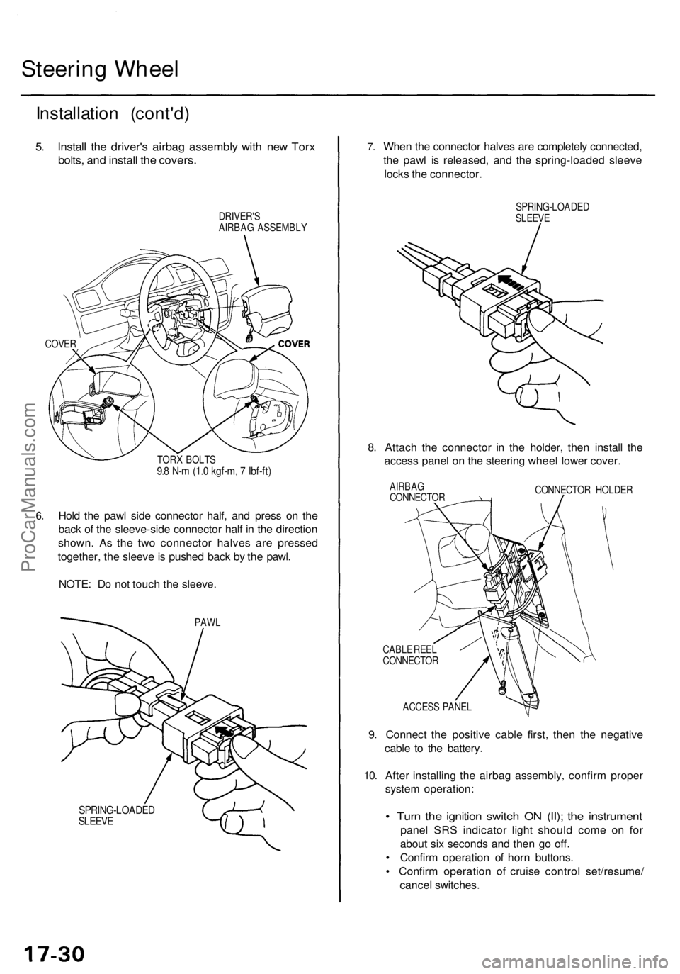
Installatio n (cont'd )
5. Instal l th e driver' s airba g assembl y wit h ne w Tor x
bolts , an d instal l th e covers .
DRIVER' S
AIRBA G ASSEMBL Y
COVER
6.
TOR X BOLT S9.8 N- m (1. 0 kgf-m , 7 Ibf-ft )
Hold th e paw l sid e connecto r half , an d pres s o n th e
bac k o f th e sleeve-sid e connecto r hal f i n th e directio n
shown . A s th e tw o connecto r halve s ar e presse d
together , th e sleev e is pushe d bac k b y th e pawl .
NOTE : D o no t touc h th e sleeve .
PAWL
SPRING-LOADE DSLEEVE
7.Whe n th e connecto r halve s ar e completel y connected ,
th e paw l i s released , an d th e spring-loade d sleev e
lock s th e connector .
SPRING-LOADE DSLEEVE
8. Attac h th e connecto r i n th e holder , the n instal l th e
acces s pane l o n th e steerin g whee l lowe r cover .
AIRBA GCONNECTO R CONNECTO
R HOLDE R
CABL E REE L
CONNECTO R
ACCES S PANE L
9. Connect the positiv e cabl e first , the n th e negativ e
cabl e t o th e battery .
10 . Afte r installin g th e airba g assembly , confir m prope r
syste m operation :
• Tur n th e ignitio n switc h O N (II) ; th e instrumen t
panel SR S indicato r ligh t shoul d com e o n fo r
abou t si x second s an d the n g o off .
• Confir m operatio n o f hor n buttons .
• Confir m operatio n o f cruis e contro l set/resume /
cance l switches .
ProCarManuals.com
Page 1417 of 1771
Dashboard
Component Removal/Installation (cont'd)
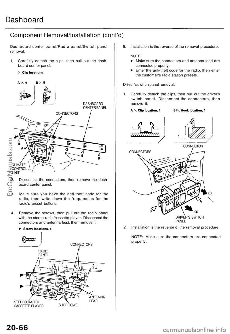
Dashboard center panel/Radio panel/Switch panel
removal:
1, Carefully detach the clips, then pull out the dash-
board center panel.
DASHBOARD
CENTER PANEL
CLIMATE
CONTROL
UNIT
2. Disconnect the connectors, then remove the dash-
board center panel.
3. Make sure you have the anti-theft code for the
radio, then write down the frequencies for the
radio's preset buttons.
4. Remove the screws, then pull out the radio panel
with the stereo radio/cassette player. Disconnect the
connectors and antenna lead, then remove it.
CONNECTORS
STEREO RADIO/
CASSETTE PLAYER
ANTENNA
LEAD
SHOP TOWEL
5. Installation is the reverse of the removal procedure.
NOTE:
Make sure the connectors and antenna lead are
connected properly.
Enter the anti-theft code for the radio, then enter
the customer's radio station presets.
Driver's switch panel removal:
1. Carefully detach the clips, then pull out the driver's
switch panel. Disconnect the connectors, then
remove it.
DRIVER'S SWITCH
PANEL
2. Installation is the reverse of the removal procedure.
NOTE: Make sure the connectors are connected
properly.
RADIO
PANEL
CONNECTOR
CONNECTORS
CONNECTORSProCarManuals.com
Page 1419 of 1771
Replacement
SRS component s ar e locate d in thi s area . Revie w th e SR S
componen t locations , precautions , an d procedure s i n th e
SR S sectio n 24 befor e preformin g repair s o r service .
NOTE:
• A n assistan t i s helpfu l whe n removin g an d installin g
th e dashboard .
• Tak e car e no t t o scratc h th e dashboard , bod y an d
relate d parts .
1 . Remove :
Dashboar d lowe r cove r (se e pag e 20-65 )
Kne e bolste r (se e pag e 20-65 )
Cente r consol e (se e pag e 20-64 )
Glov e bo x
Kic k panel s (se e pag e 20-63 )
2 . Remov e th e dashboar d cente r trim .
DASHBOAR DCENTER TRI M
3. Mak e sur e yo u hav e th e anti-thef t cod e fo r th e radio ,
the n writ e dow n th e frequencie s fo r th e radio' s prese t
buttons .
Clip location s
ProCarManuals.com
Page 1549 of 1771
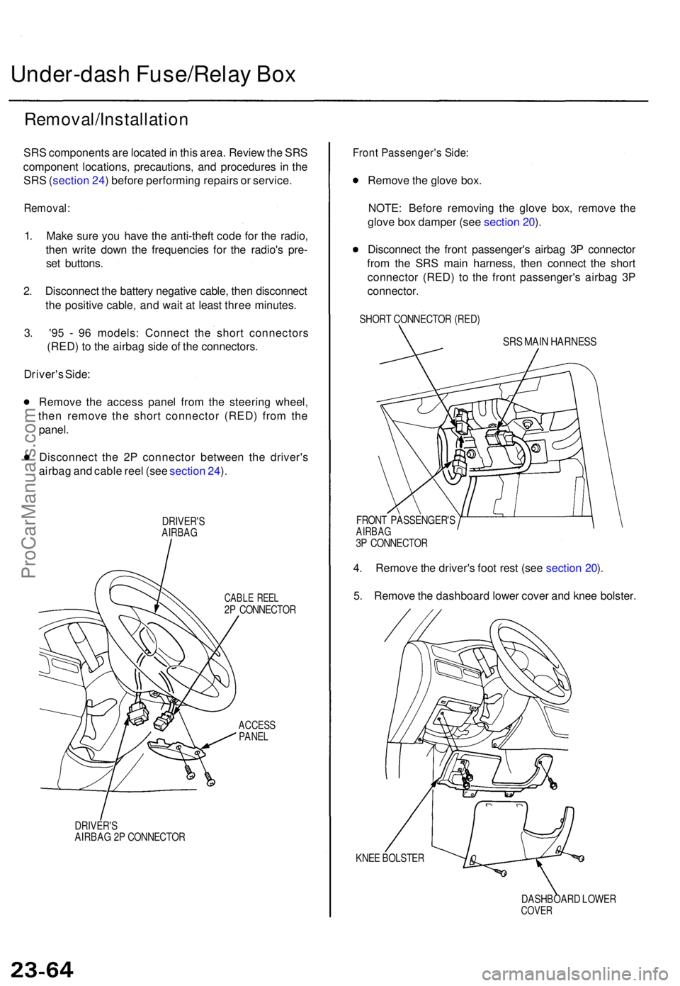
Under-dash Fuse/Rela y Bo x
Removal/Installatio n
SRS component s ar e locate d in thi s area . Revie w th e SR S
componen t locations , precautions , an d procedure s i n th e
SR S (sectio n 24 ) befor e performin g repair s o r service .
Removal :
1. Mak e sur e yo u hav e th e anti-thef t cod e fo r th e radio ,
the n writ e dow n th e frequencie s fo r th e radio' s pre -
se t buttons .
2 . Disconnec t th e batter y negativ e cable , the n disconnec t
th e positiv e cable , an d wai t a t leas t thre e minutes .
3 . '9 5 - 9 6 models : Connec t th e shor t connector s
(RED ) t o th e airba g sid e o f th e connectors .
Driver' s Side :
Remov e th e acces s pane l fro m th e steerin g wheel ,
the n remov e th e shor t connecto r (RED ) fro m th e
panel .
Disconnec t th e 2 P connecto r betwee n th e driver' s
airba g an d cabl e ree l (se e sectio n 24 ).
DRIVER' SAIRBAG
CABLE REE L2P CONNECTO R
ACCESSPANEL
DRIVER' SAIRBAG 2 P CONNECTO R
Front Passenger' s Side :
Remov e th e glov e box .
NOTE : Befor e removin g th e glov e box , remov e th e
glov e bo x dampe r (se e sectio n 20 ).
Disconnec t th e fron t passenger' s airba g 3 P connecto r
fro m th e SR S mai n harness , the n connec t th e shor t
connecto r (RED ) t o th e fron t passenger' s airba g 3 P
connector .
SHORT CONNECTO R (RED )
SRS MAI N HARNES S
FRONT PASSENGER' SAIRBAG3P CONNECTO R
4. Remov e th e driver' s foo t res t (se e sectio n 20 ).
5 . Remov e th e dashboar d lowe r cove r an d kne e bolster .
KNEE BOLSTE R
DASHBOARD LOWE R
COVER
ProCarManuals.com
Page 1552 of 1771
Steering Loc k Replacemen t
SRS component s ar e locate d in thi s area . Revie w th e SR S
componen t locations , precautions , an d procedure s i n th e
SR S (sectio n 24 ) befor e performin g repair s o r service .
Removal :
1 . Mak e sur e yo u hav e th e anti-thef t cod e fo r th e radio ,
then writ e dow n th e frequencie s fo r th e radio' s pre -
set buttons .
2. Disconnec t th e batter y negativ e cable , the n disconnec t
th e positiv e cable , an d wai t a t leas t thre e minutes .
3 . Remov e th e dashboar d lowe r cove r an d kne e bolster .
KNEEBOLSTE R
DASHBOARD LOWE R COVE R
4. Remov e th e steerin g colum n covers .
STEERIN G COLUM NUPPER COVE R
STEERIN GCOLUMNLOWERCOVER
5. Disconnec t th e connector s fro m th e switch .
SWITCH
HARNES S
IGNITIO N SWITC H
7 P CONNECTO R7
P CONNECTO R
ProCarManuals.com