1995 ACURA TL fog light
[x] Cancel search: fog lightPage 209 of 1771
Idle Contro l Syste m
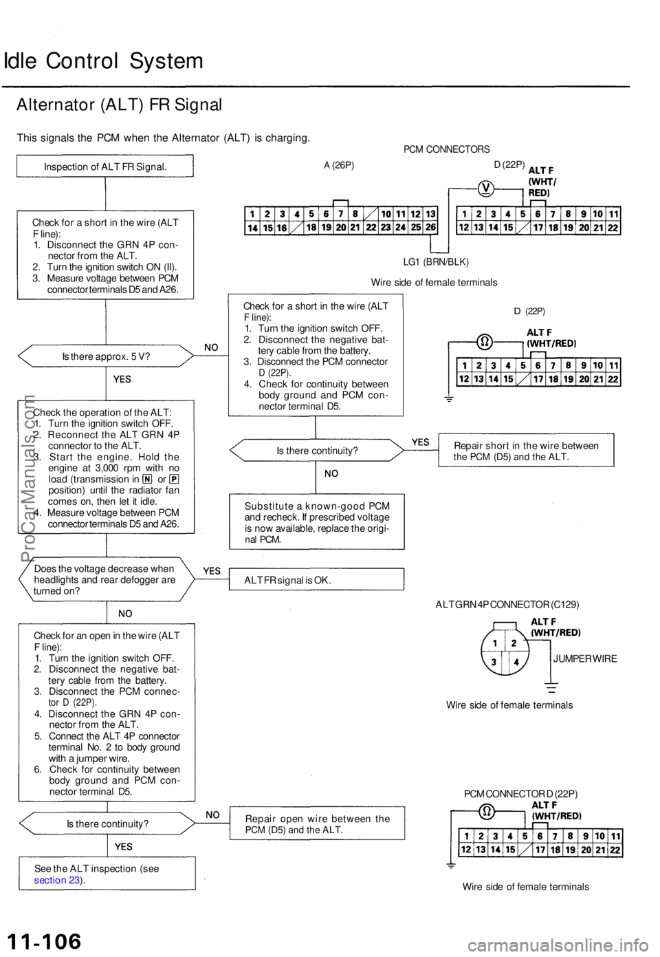
Alternato r (ALT ) F R Signa l
This signal s th e PC M whe n th e Alternato r (ALT ) i s charging .
Is ther e approx . 5 V ?
Chec k th e operatio n o f th e ALT :
1 . Tur n th e ignitio n switc h OFF .
2 . Reconnec t th e AL T GR N 4 P
connecto r t o th e ALT .
3 . Star t th e engine . Hol d th e
engin e a t 3,00 0 rp m wit h n o
loa d (transmissio n in o r
position ) unti l th e radiato r fa n
come s on , the n le t i t idle .
4 . Measur e voltag e betwee n PC M
connecto r terminal s D 5 an d A26 .
Doe s th e voltag e decreas e whe n
headlight s an d rea r defogge r ar e
turne d on ?
Chec k fo r a n ope n in th e wir e (AL T
F line) :
1 . Tur n th e ignitio n switc h OFF .
2 . Disconnec t th e negativ e bat -
ter y cabl e fro m th e battery .
3 . Disconnec t th e PC M connec -
tor D (22P) .4. Disconnec t th e GR N 4 P con -
necto r fro m th e ALT .
5 . Connec t th e AL T 4 P connecto r
termina l No . 2 to bod y groun d
with a jumpe r wire .6. Chec k fo r continuit y betwee n
bod y groun d an d PC M con -
necto r termina l D5 .
I s ther e continuity ?
Se e th e AL T inspectio n (se e
sectio n 23 ).
PC M CONNECTOR S
A (26P)D (22P )
LG1 (BRN/BLK )
Wire sid e o f femal e terminal s
Chec k fo r a shor t i n th e wir e (AL T
F line) :1. Tur n th e ignitio n switc h OFF .
2 . Disconnec t th e negativ e bat -
ter y cabl e fro m th e battery .
3 . Disconnec t th e PC M connecto r
D (22P) .4. Chec k fo r continuit y betwee n
bod y groun d an d PC M con -
necto r termina l D5 .
D (22P )
Is ther e continuity ? Repai
r shor t i n th e wir e betwee nthe PC M (D5 ) and th e ALT .
Substitut e a known-goo d PC M
an d recheck . I f prescribe d voltag e
i s no w available , replac e th e origi -
nal PCM .
ALT F R signa l i s OK .
ALT GR N 4P CONNECTO R (C129 )
JUMPE R WIR E
Wir e sid e o f femal e terminal s
Repai r ope n wir e betwee n th e
PC M (D5 ) and th e ALT .
Wire sid e o f femal e terminal s
PC
M CONNECTO R D (22P )
Chec
k fo r a shor t i n th e wir e (AL T
F line) :
1 . Disconnec t th e GR N 4 P con -
necto r fro m th e ALT .
2 . Tur n th e ignitio n switc h O N (II) .
3 . Measur e voltag e betwee n PC M
connecto r terminal s D 5 an d A26 .
Inspectio
n o f AL T F R Signal .
ProCarManuals.com
Page 217 of 1771

Idle Contro l Syste m
Idle Spee d Settin g
Inspection/Adjustmen t
NOTE:
Before settin g th e idl e speed , chec k th e followin g
items :
— Th e MI L ha s no t bee n reporte d on .
— Ignitio n timin g
— Spar k plug s
— Ai r cleane r (ACL )
— PC V syste m
(Canada ) Pul l th e parkin g brak e leve r up . Star t th e
engine , the n chec k tha t th e headlight s ar e off .
1 . Star t th e engine . Hol d th e engin e a t 3,00 0 rp m wit h
no loa d (transmissio n i n o r position ) unti l th e
radiato r fa n come s on , the n le t i t idle .
2 . Connec t a OBDI I sca n too l (se e pag e 11-32 ) o r
tachometer .
• Connec t a tachomete r t o th e ignitio n contro l
module (ICM ) secondary , or.. .
TACHOMETE R
ICM
Remov e th e rubbe r ca p fro m th e tachomete r
connecto r an d connec t a tachometer .
TACHOMETE R TACHOMETE R
CONNECTOR
RUBBERCAP
3. Disconnec t th e IA C valv e connector .
4.
5 .
IA C VALV E
Start th e engin e wit h th e accelerato r peda l slightl y
depressed . Stabiliz e th e rp m a t 1,000 , the n slowl y
releas e th e peda l unti l th e engin e idles .
Check idlin g in no-loa d conditions : headlights , blow -
er fan , rea r defogger , radiato r fan , an d ai r conditione r
ar e no t operating .
Idl e spee d shoul d be :
480 5 0 rp m
(in o r position )
Adjus t th e idl e speed , i f necessary , b y turnin g th e
idl e adjustin g screw .
NOTE : Afte r adjustin g th e idl e spee d i n thi s step ,
rechec k th e ignitio n timin g (se e sectio n 23 ).
I f i t i s ou t o f spec , g o bac k t o ste p 4 .
IDL E ADJUSTIN G SCRE W
ProCarManuals.com
Page 542 of 1771
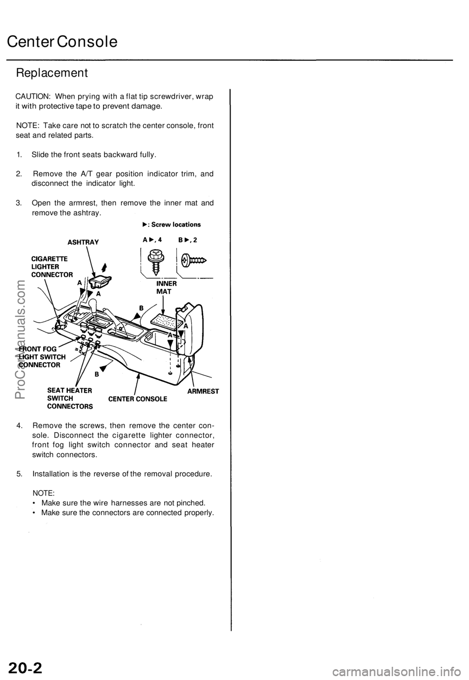
Center Console
Replacement
CAUTION: When prying with a flat tip screwdriver, wrap
it with protective tape to prevent damage.
NOTE: Take care not to scratch the center console, front
seat and related parts.
1. Slide the front seats backward fully.
2. Remove the A/T gear position indicator trim, and
disconnect the indicator light.
3. Open the armrest, then remove the inner mat and
remove the ashtray.
4. Remove the screws, then remove the center con-
sole. Disconnect the cigarette lighter connector,
front fog light switch connector and seat heater
switch connectors.
5. Installation is the reverse of the removal procedure.
NOTE:
• Make sure the wire harnesses are not pinched.
• Make sure the connectors are connected properly.ProCarManuals.com
Page 888 of 1771
Idle Contro l Syste m
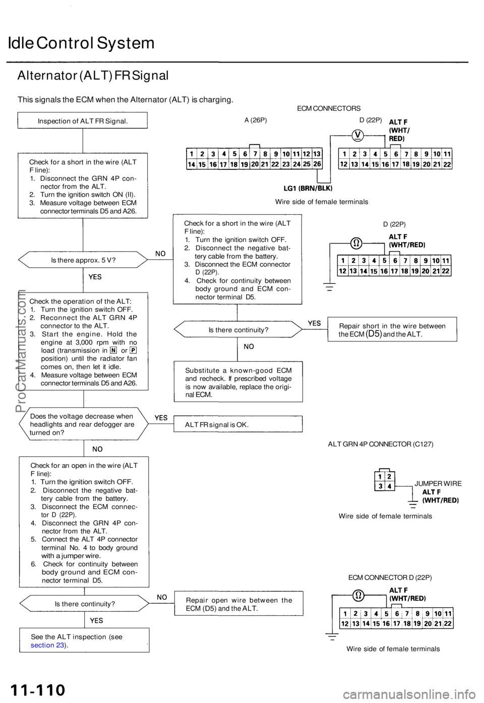
Alternato r (ALT ) F R Signa l
This signal s th e EC M whe n th e Alternato r (ALT ) i s charging .
Is ther e approx . 5 V ?
Chec k th e operatio n o f th e ALT :
1 . Tur n th e ignitio n switc h OFF .
2 . Reconnec t th e AL T GR N 4 P
connecto r t o th e ALT .
3 . Star t th e engine . Hol d th e
engin e a t 3,00 0 rp m wit h n o
loa d (transmissio n in o r
position ) unti l th e radiato r fa n
come s on , the n le t i t idle .
4 . Measur e voltag e betwee n EC M
connecto r terminal s D 5 an d A26 .
Doe s th e voltag e decreas e whe n
headlight s an d rea r defogge r ar e
turne d on ?
Chec k fo r a n ope n in th e wir e (AL T
F line) :
1. Tur n th e ignitio n switc h OFF .2. Disconnec t th e negativ e bat -
ter y cabl e fro m th e battery .
3 . Disconnec t th e EC M connec -
tor D (22P) .4. Disconnec t th e GR N 4 P con -
necto r fro m th e ALT .
5 . Connec t th e AL T 4 P connecto r
termina l No . 4 to bod y groun d
with a jumpe r wire .6. Chec k fo r continuit y betwee nbody groun d an d EC M con -necto r termina l D5 .
I s ther e continuity ?
Se e th e AL T inspectio n (se e
sectio n 23 ). EC
M CONNECTOR S
A (26P)D (22P)
Wire sid e o f femal e terminal s
D (22P)
Repai r shor t i n th e wir e betwee nthe EC M (D5 ) and th e ALT .
ALT F R signa l i s OK .
ALT GR N 4P CONNECTO R (C127 )
JUMPE R WIR E
Wir e sid e o f femal e terminal s
Repai r ope n wir e betwee n th e
ECM (D5 ) and th e ALT .
ECM CONNECTO R D (22P )
Wir e sid e o f femal e terminal s
Substitut
e a known-goo d EC M
an d recheck . I f prescribe d voltag e
i s no w available , replac e th e origi -
nal ECM .
Is ther e continuity ?
Chec
k fo r a shor t i n th e wir e (AL T
F line) :
1 . Tur n th e ignitio n switc h OFF .
2 . Disconnec t th e negativ e bat -
ter y cabl e fro m th e battery .
3 . Disconnec t th e EC M connecto r
D (22P) .4. Chec k fo r continuit y betwee n
bod y groun d an d EC M con -
necto r termina l D5 .
Chec
k fo r a shor t i n th e wir e (AL T
F line) :
1 . Disconnec t th e GR N 4 P con -
necto r fro m th e ALT .
2 . Tur n th e ignitio n switc h O N (II) .
3 . Measur e voltag e betwee n EC M
connecto r terminal s D 5 an d A26 .
Inspectio
n o f AL T F R Signal .
ProCarManuals.com
Page 895 of 1771
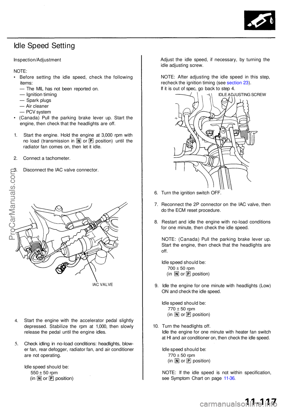
Idle Spee d Settin g
Inspection/Adjustmen t
NOTE:
• Befor e settin g th e idl e speed , chec k th e followin g
items:
— Th e MI L ha s no t bee n reporte d on .
— Ignitio n timin g
— Spar k plug s
— Ai r cleane r
— PC V syste m
• (Canada ) Pul l th e parkin g brak e leve r up . Star t th e
engine , the n chec k tha t th e headlight s ar e off .
1 . Star t th e engine . Hol d th e engine at 3,00 0 rp m wit h
no loa d (transmissio n i n o r position ) unti l th e
radiato r fa n come s on , the n le t i t idle .
2 . Connec t a tachometer .
3 . Disconnec t th e IA C valv e connector .
IAC VALV E
4.
5.
Star t th e engin e wit h th e accelerato r peda l slightl y
depressed . Stabiliz e th e rp m a t 1,000 , the n slowl y
releas e th e peda l unti l th e engin e idles .
Check idlin g in no-loa d conditions : headlights , blow -
er fan , rea r defogger , radiato r fan , an d ai r conditione r
ar e no t operating .
Idl e spee d shoul d be :
550 ± 5 0 rp m
(in o r position )
Adjust th e idl e speed , i f necessary, by turnin g th e
idl e adjustin g screw .
NOTE : Afte r adjustin g th e idl e spee d i n thi s step ,
rechec k th e ignitio n timin g (se e sectio n 23 ).
I f i t i s ou t o f spec , g o bac k t o ste p 4 .
IDL E ADJUSTIN G SCRE W
6. Tur n th e ignitio n switc h OFF .
7 . Reconnec t th e 2 P connecto r o n th e IA C valve , the n
d o th e EC M rese t procedure .
8 . Restar t an d idl e th e engine with no-loa d condition s
fo r on e minute , the n chec k th e idl e speed .
NOTE : (Canada ) Pul l th e parkin g brak e leve r up .
Star t th e engine , the n chec k tha t th e headlight s ar e
off.
Idle spee d shoul d be :
700 ± 5 0 rp m
(in o r position )
9 . Idl e th e engin e fo r on e minut e wit h headlight s (Low )
O N an d chec k th e idl e speed .
Idl e spee d shoul d be :
770 ± 5 0 rp m
(in o r position )
10 . Tur n th e headlight s off .
Idl e th e engin e fo r on e minut e wit h heate r fa n switc h
a t H I an d ai r conditione r on , the n chec k th e idl e speed .
Idl e spee d shoul d be :
770 ± 5 0 rp m
(in o r position )
NOTE : I f th e idl e spee d i s no t withi n specification ,
se e Sympto m Char t o n pag e 11-36 .
ProCarManuals.com
Page 926 of 1771
Intake Ai r Syste m Emissio
n Contro l Syste m
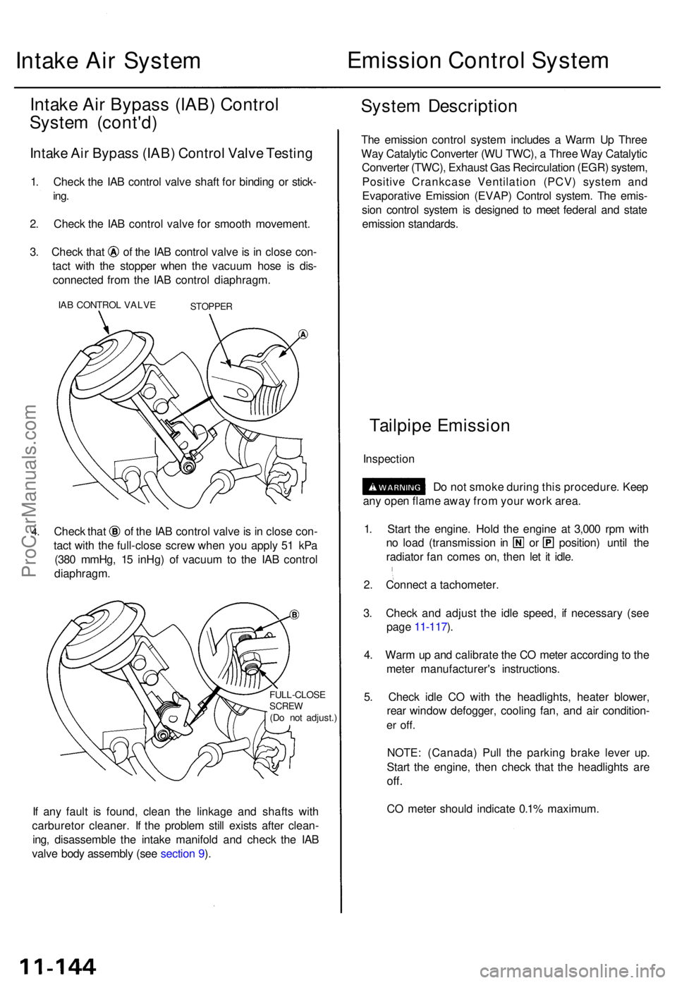
Intake Ai r Bypas s (IAB ) Contro l
Syste m (cont'd )
Intake Ai r Bypas s (IAB ) Contro l Valv e Testin g
1. Chec k th e IA B contro l valv e shaf t fo r bindin g o r stick -
ing.
2. Chec k th e IA B contro l valv e fo r smoot h movement .
3. Chec k tha t o f th e IA B contro l valv e is i n clos e con -
tac t wit h th e stoppe r whe n th e vacuu m hos e i s dis -
connecte d fro m th e IA B contro l diaphragm .
IAB CONTRO L VALV ESTOPPE R
4.Chec k tha t o f th e IA B contro l valv e is in clos e con -
tac t wit h th e full-clos e scre w whe n yo u appl y 5 1 kP a
(38 0 mmHg , 1 5 inHg ) o f vacuu m to th e IA B contro l
diaphragm .
FULL-CLOS ESCREW(Do no t adjust. )
If an y faul t i s found , clea n th e linkag e an d shaft s wit h
carbureto r cleaner . I f th e proble m stil l exist s afte r clean -
ing , disassembl e th e intak e manifol d an d chec k th e IA B
valv e bod y assembl y (se e sectio n 9 ).
Syste m Descriptio n
The emissio n contro l syste m include s a War m U p Thre e
Wa y Catalyti c Converte r (W U TWC) , a Thre e Wa y Catalyti c
Converte r (TWC) , Exhaus t Ga s Recirculatio n (EGR ) system ,
Positiv e Crankcas e Ventilatio n (PCV ) syste m an d
Evaporativ e Emissio n (EVAP ) Contro l system . Th e emis -
sio n contro l syste m is designe d t o mee t federa l an d stat e
emissio n standards .
Tailpipe Emissio n
Inspectio n
Do no t smok e durin g thi s procedure . Kee p
an y ope n flam e awa y fro m you r wor k area .
1 . Star t th e engine . Hol d th e engin e a t 3,00 0 rp m wit h
no loa d (transmissio n i n o r position ) unti l th e
radiato r fa n come s on , the n le t i t idle .
2 . Connec t a tachometer .
3 . Chec k an d adjus t th e idl e speed , i f necessar y (se e
pag e 11-117 ).
4 . War m u p an d calibrat e th e C O mete r accordin g to th e
mete r manufacturer' s instructions .
5 . Chec k idl e C O wit h th e headlights , heate r blower ,
rea r windo w defogger , coolin g fan , an d ai r condition -
er off .
NOTE : (Canada ) Pul l th e parkin g brak e leve r up .
Star t th e engine , the n chec k tha t th e headlight s ar e
off.
CO mete r shoul d indicat e 0.1 % maximum .
ProCarManuals.com
Page 1541 of 1771
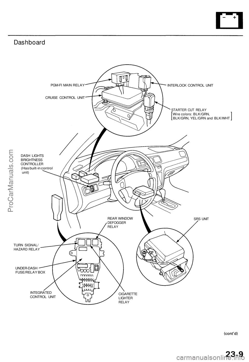
Dashboard
PGM-FI MAI N RELA Y
CRUIS E CONTRO L UNI T
DAS H LIGHT S
BRIGHTNES S
CONTROLLE R(Has built-i n contro lunit)
TUR N SIGNAL /HAZARD RELA Y
UNDER-DAS H
FUSE/RELA Y BO X INTERLOC
K CONTRO L UNI T
STARTE R CU T RELA YWire colors : BLK/GRN ,BLK/GRN, YEL/GR N an d BLK/WH T
SRS UNI T
INTEGRATE D
CONTRO L UNI TCIGARETT ELIGHTERRELAY
REAR WINDO WDEFOGGE RRELAY
ProCarManuals.com
Page 1542 of 1771
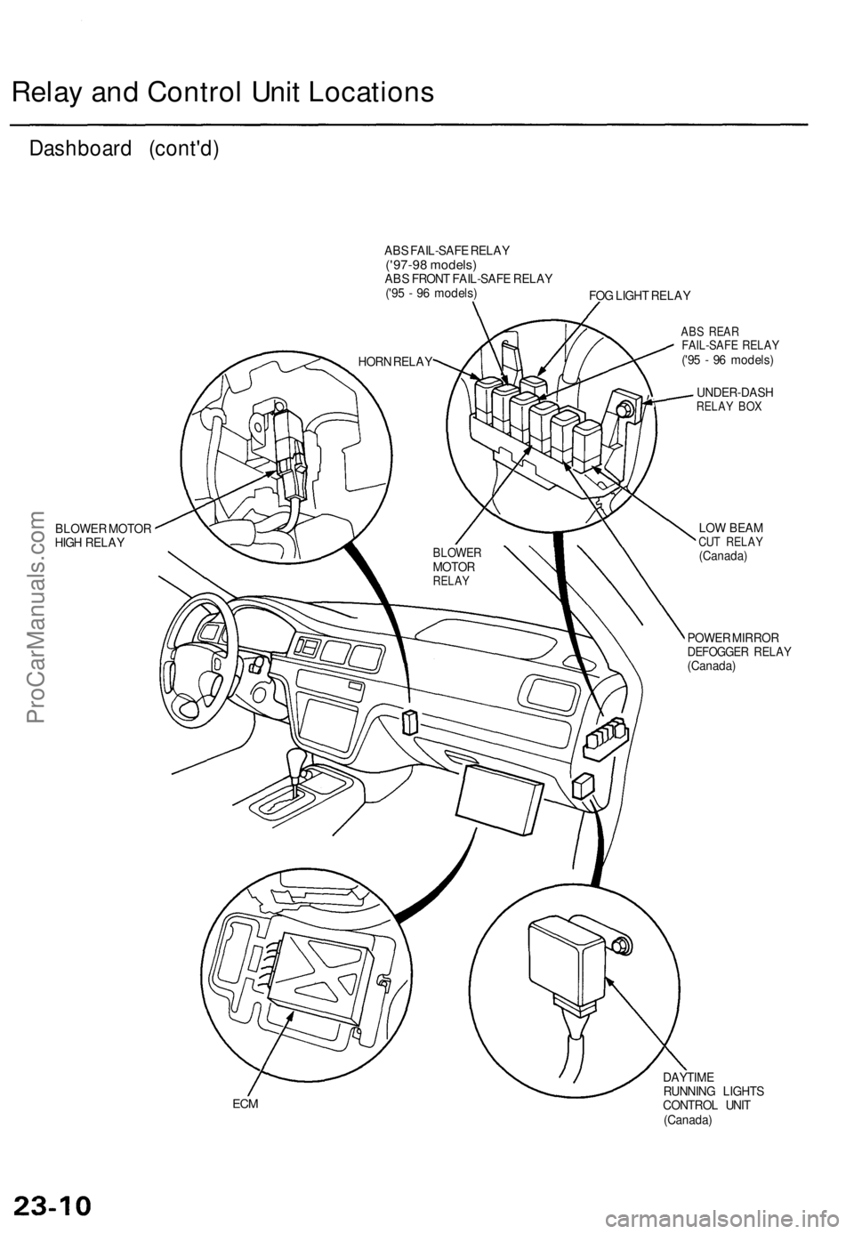
Relay and Control Unit Locations
Dashboard (cont'd)
ABS FAIL-SAFE RELAY
('97-98 models)
ABS FRONT FAIL-SAFE RELAY
('95 - 96 models)
FOG LIGHT RELAY
BLOWER MOTOR
HIGH RELAY
ABS REAR
FAIL-SAFE RELAY
('95 - 96 models)
UNDER-DASH
RELAY BOX
LOW BEAM
CUT RELAY
(Canada)
POWER MIRROR
DEFOGGER RELAY
(Canada)
ECM
DAYTIME
RUNNING LIGHTS
CONTROL UNIT
(Canada)
BLOWER
MOTOR
RELAY
HORN RELAYProCarManuals.com