Page 1547 of 1771
Power Relay s
Relay Tes t
NOTE : Se e pag e 23-18 9 fo r tur n signal/hazar d rela y inpu t
test .
Normally-ope n type :
1 . Chec k fo r continuit y betwee n th e terminals .
Ther e shoul d b e continuit y betwee n th e No . 1 an d
No . 3 terminal s whe n powe r an d groun d ar e con -
necte d to th e No . 2 an d No . 4 terminals .
Ther e shoul d b e n o continuit y betwee n th e No . 1
an d No . 3 terminal s whe n powe r i s disconnected .
('95-96 models )
Cigarett e lighte r rela y
Fog ligh t rela y
Horn rela y
AB S fron t fail-saf e rela y
AB S rea r fail-saf e rela y
AB S fail-saf e rela y ('9 7 - 9 8 models )
Blowe r moto r rela y
Powe r mirro r defogge r rela y (Canad a an d '9 8 USA )
Tailligh t rela y
Powe r windo w rela y AB
S pum p moto r rela y
Radiato r fa n rela y
Condense r fa n rela y
A/C compresso r clutc h rela y
• Blowe r moto r hig h rela y
Starte r cu t rela y
ProCarManuals.com
Page 1548 of 1771
Headlight relay
Rear window defogger relay
Normally-closed Type:
1. Check for continuity between the terminals.
There should be no continuity between the No. 1
and No. 3 terminals when power and ground are
connected to the No. 2 and No. 4 terminals.
There should be continuity between the No. 1 and
No. 3 terminals when power is disconnected.
Low beam cut relay (Canada)
Five-terminal type:
1. Check for continuity between the terminals.
There should be continuity between the No. 1 and
No. 2 terminals when power and ground are con-
nected to the No. 3 and No. 5 terminals.
There should be continuity between the No. 2 and
No. 4 terminals when power is disconnected.
Dimmer relay
Intermittent wiper relay
Moonroof open relay
Moonroof close relayProCarManuals.com
Page 1631 of 1771
FOG LIGH T RELA YTest, pag e 23-6 2
DR L INDICATO R LIGH T (Canada )
LOW BEA M CU T RELA Y
(Canada )Test, pag e 23-6 2
FO G LIGH T
SWITC H
Replacement , pag e 23-26 9
Test , pag e 23-17 0
COMBINATIO N LIGH T SWITC H
Test , pag e 23-16 2
Replacement , pag e 23-16 6
DAYTIM E RUNNIN G LIGHT S
CONTRO L UNI T (Canada )
Inpu t Test , pag e 23-16 4
A/
T GEA R POSITIO N
INDICATO R PANE L LIGH T
Replacement , pag e 23-17 3
HIG
H BEA M INDICATO R LIGH T
Bul b Locations , pag e 23-11 5
ProCarManuals.com
Page 1640 of 1771

Fog Ligh t
Switc h Tes t
SRS component s ar e locate d i n thi s area . Revie w th e
SR S componen t locations , precautions , an d procedure s
i n th e SR S (sectio n 24 ) befor e performin g repair s o r ser -
vice .
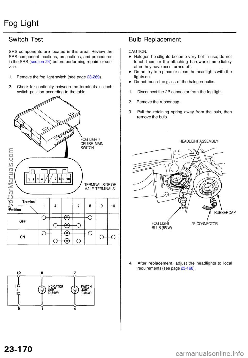
1 . Remov e th e fo g ligh t switc h (se e pag e 23-269 ).
2 . Chec k fo r continuit y betwee n th e terminal s i n eac h
switc h positio n accordin g t o th e table .
Bulb Replacemen t
FOG LIGHT /
CRUIS E MAI N
SWITC H
TERMINA L SID E O FMAL E TERMINAL S
CAUTION:
Halogen headlight s becom e ver y ho t i n use ; d o no t
touc h the m o r th e attachin g hardwar e immediatel y
afte r the y hav e bee n turne d off .
D o no t tr y to replac e o r clea n th e headlight s wit h th e
light s on .
D o no t touc h th e glas s o f th e haloge n bulbs .
1 . Disconnec t th e 2 P connecto r fro m th e fo g light .
2 . Remov e th e rubbe r cap .
3 . Pul l th e retainin g sprin g awa y fro m th e bulb , the n
remov e th e bulb .
HEADLIGH T ASSEMBL Y
FO G LIGH T
BUL B (5 5 W ) RUBBE
R CA P
2 P CONNECTO R
4. Afte r replacement , adjus t th e headlight s t o loca l
requirement s (se e pag e 23-168 ).
ProCarManuals.com
Page 1673 of 1771

Rear Windo w Defogge r
Function Tes t
CAUTION : B e carefu l no t t o scratc h o r damag e th e defog -
ger wire s wit h th e teste r probe .
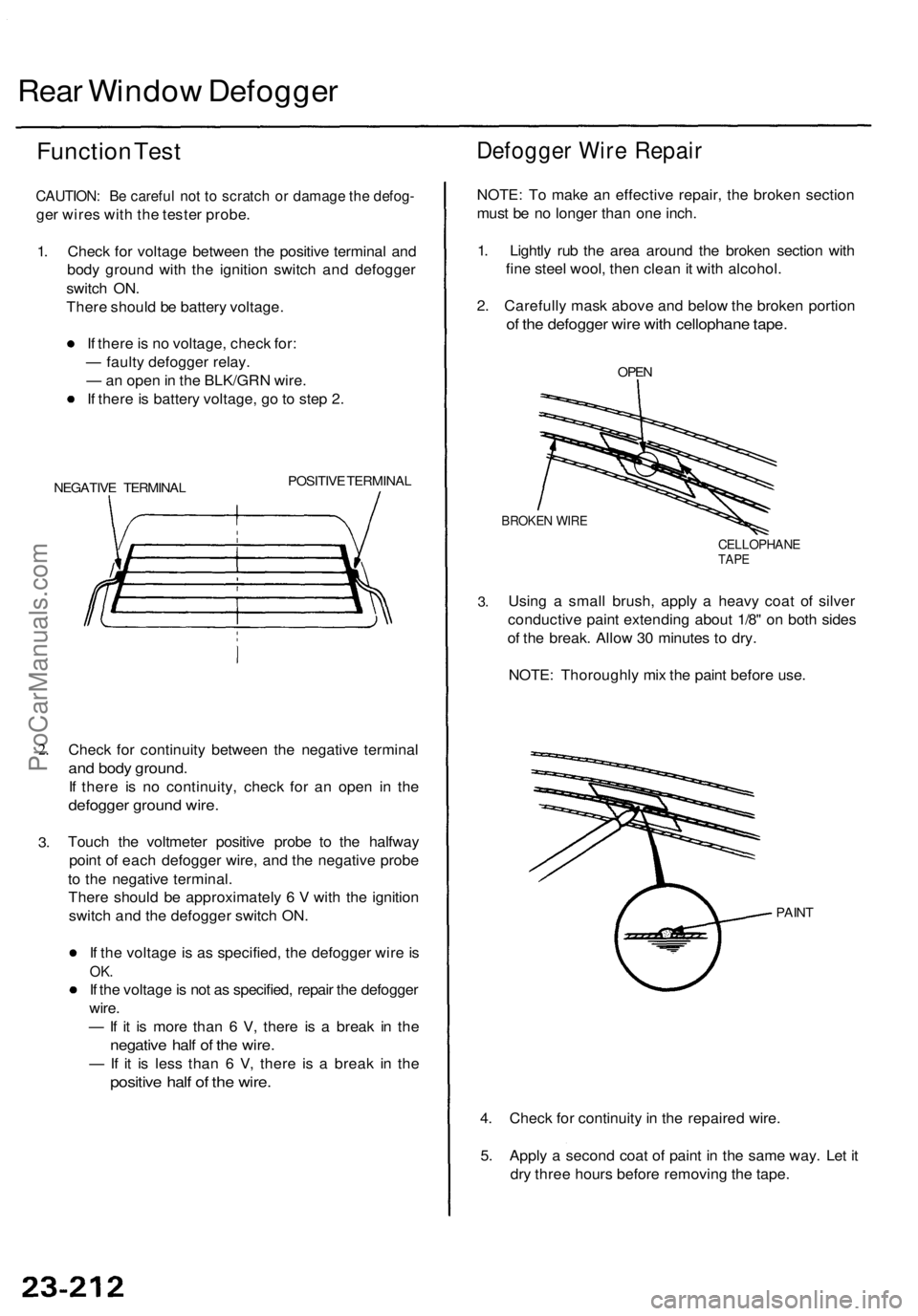
1 . Chec k fo r voltag e betwee n th e positiv e termina l an d
bod y groun d wit h th e ignitio n switc h an d defogge r
switc h ON .
Ther e shoul d b e batter y voltage .
I f ther e is n o voltage , chec k for :
— fault y defogge r relay .
— an ope n in th e BLK/GR N wire .
I f ther e is batter y voltage , g o to ste p 2 .
NEGATIV E TERMINA L POSITIV
E TERMINA L
2.
3 .
Chec k fo r continuit y betwee n th e negativ e termina l
and bod y ground .
If ther e i s n o continuity , chec k fo r a n ope n i n th e
defogge r groun d wire .
Touc h th e voltmete r positiv e prob e t o th e halfwa y
poin t o f eac h defogge r wire , an d th e negativ e prob e
t o th e negativ e terminal .
Ther e shoul d b e approximatel y 6 V with th e ignitio n
switc h an d th e defogge r switc h ON .
I f th e voltag e is a s specified , th e defogge r wir e is
OK .
If th e voltag e is no t a s specified , repai r th e defogge r
wire .
— If i t i s mor e tha n 6 V , ther e i s a brea k i n th e
negativ e hal f o f th e wire .
— If i t i s les s tha n 6 V , ther e i s a brea k i n th e
positiv e hal f o f th e wire .
Defogge r Wir e Repai r
NOTE: T o mak e a n effectiv e repair , th e broke n sectio n
mus t b e n o longe r tha n on e inch .
1 . Lightl y ru b th e are a aroun d th e broke n sectio n wit h
fin e stee l wool , the n clea n it wit h alcohol .
2 . Carefull y mas k abov e an d belo w th e broke n portio n
of th e defogge r wir e wit h cellophan e tape .
OPEN
BROKE N WIR E
CELLOPHAN ETAPE
3.Usin g a smal l brush , apply a heav y coa t o f silve r
conductiv e pain t extendin g abou t 1/8 " o n bot h side s
o f th e break . Allo w 3 0 minute s t o dry .
NOTE : Thoroughl y mi x th e pain t befor e use .
PAIN T
4. Chec k fo r continuit y in th e repaire d wire .
5 . Appl y a secon d coa t o f pain t i n th e sam e way . Le t i t
dr y thre e hour s befor e removin g th e tape .
ProCarManuals.com
Page 1681 of 1771
Switch Tes t
1. Remov e th e switc h a s describe d i n Functio n Tes t
(see pag e 23-222 ).
2 . Chec k fo r continuit y betwee n th e terminal s i n eac h
switc h positio n accordin g t o th e table .
Mirro r Switch :
Defogge r Switc h (Canad a an d '9 8 USA) :
Switc h Light : US
A model :
POWERMIRRO RSWITCH
Canada an d '9 8 US A models :
TERMINA L SID E
O F MAL E TERMINAL S
ProCarManuals.com
Page 1721 of 1771
Main Switc h Tes t
SRS component s ar e locate d in thi s area . Revie w th e SR S
componen t locations , precautions , an d procedure s i n th e
SR S (sectio n 24 ) befor e performin g repair s o r service .
1 . Carefull y pr y th e switche s ou t o f th e dashboard .
2 . Disconnec t th e connector s fro m th e switches .
MAINSWITC H
DRIVER' S SWITC H
PANEL
FOG LIGHT/CRUIS E MAI NSWITC H
TERMINA L SID E O F MAL E TERMINAL S
3. Chec k fo r continuit y betwee n th e terminal s i n eac h
switc h positio n accordin g t o th e table .
I f ther e i s n o continuity , replac e th e switch .
ProCarManuals.com