1995 ACURA TL oil temperature
[x] Cancel search: oil temperaturePage 28 of 1771

Lubrication Points
For the details of lubrication points and types of lubricants to be applied, refer to the illustrated index and various work
procedures (such as Assembly/Reassembly, Replacement, Overhaul, Installation, etc.) contained in each section.
No.
1
2
3
4
5
6
7
8
9
10
11
12
13
14
15
16
17
18
19
20
21
LUBRICATION POINTS
Engine
Transmission
Brake Line (Includes Anti-lock brake line)
Power steering gearbox
Steering boots
Throttle cable end
Steering ball joints
Shift lever (Automatic transmission)
Pedal linkage
Intermediate shaft
Brake master cylinder pushrod
Fuel
fill
lid
Trunk hinges
Door hinges upper and lower
Door opening detents
Hood hinges and hood latch
Brake pipe joint (Front and rear wheel house)
Caliper Piston seal, Dust seal,
Caliper pin, Piston
Power steering system
Differential
A/C compressor
LUBRICANT
API Service Grade: Use SH "Energy Conserving II" or SJ
"Energy Conserving" grade oil.
The oil container may also display the API Certification
mark shown below. Make sure it says "For Gasoline
Engines."
SAE Viscosity: See chart below.
Genuine Honda Premium Formula Automatic
Transmission Fluid (ATF)*1
Genuine Honda DOT3 Brake Fluid*2
Steering grease P/N 08733 - B070E
Multi-purpose grease
Honda White Lithium Grease
Rust preventives
Silicone grease
Genuine Honda Power Steering Fluid-V or S*3
Hypoid gear Oil API service GL4 or GL5
Viscosity:
at above -18°C (0°F): SAE 90
at less than -18°C (0°F): SAE 80 W-90
Compressor oil:
DENSO: ND-OIL8 (P/N 38897 - PR7 - A01 AH or 38899 -
PR7-A01)
(For Refrigerant: HFC-134a (R-134a))
API SERVICE LABEL
API CERTIFICATION MARK
Recommended Engine Oil
Engine oil viscosity for ambient temperature ranges
NOTE: The following information as marked *1, *2 and *3 on above chart details for 1997 model:
*1: Always use Genuine Honda Premium Formula Automatic Transmission Fluid (ATF). Using a non-Honda ATF can affect
shift quality.
*2: Always use Genuine Honda DOT3 Brake Fluid. Using a non-Honda brake fluid can cause corrosion and decrease the
life of the system.
*3: Always use Genuine Honda Power Steering Fluid-V or S. Using any other type of power steering fluid or automatic
transmission fluid can cause increase wear and poor steering in cold weather.ProCarManuals.com
Page 75 of 1771

22. Remove the positive crankcase ventilation (PCV)
hose.
23. Remove the bolt securing the automatic transmis-
sion fluid (ATF) dipstick tube bracket.
6 x 1.0 mm
12 N-m (1.2 kgf-m,
8.7 Ibf-ft)
ATF BRACKET
DIPSTICK TUBE
BRACKET
PCV HOSE
24.
Remove the engine wire harness connectors and
wire harness clamps from the cylinder heads and
intake manifold.
Six injector connectors
Six ignition coil connectors
Throttle position sensor connector
CKP/CYP sensor connector
Intake air temperature (IAT) sensor connector
Exhaust gas recirculation (EGR) valve lift sensor
connector
Idle air control (IAC) valve connector
Engine coolant temperature (ECT) sensor con-
nector
ECT gauge sending unit connector
Engine oil temperature sensor connector
Left primary heated oxygen sensor (left primary
HO2S) connector
Right primary heated oxygen sensor (right pri-
mary HO2S) connector
Evaporative emission (EVAP) purge control
solenoid valve connector ('97 - '98)
25. Remove the inlet pipe mounting bolts from the right
cylinder head cover.
26. Remove the vacuum hoses and breather hose.
6 x 1.0 mm
12 N-m (1.2 kgf-m, 8.7 Ibf-ft)
BREATHER
HOSE
VACUUM
HOSES
27. Remove the six ignition coils from the left and right
cylinder head covers.
6 x 1.0 mm
12 N-m (1.2 kgf-m, 8.7 Ibf-ft)
IGNITION
COILProCarManuals.com
Page 120 of 1771
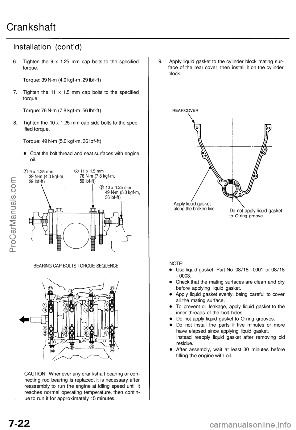
Crankshaft
BEARING CAP BOLTS TORQUE SEQUENCE
CAUTION: Whenever any crankshaft bearing or con-
necting rod bearing is replaced, it is necessary after
reassembly to run the engine at idling speed until it
reaches normal operating temperature, then contin-
ue to run it for approximately 15 minutes.
9. Apply liquid gasket to the cylinder block mating sur-
face of the rear cover, then install it on the cylinder
block.
REAR COVER
Apply liquid gasket
along the broken line.
Do not apply liquid gasket
to O-ring groove.
NOTE:
Use liquid gasket, Part No. 08718 - 0001 or 08718
- 0003.
Check that the mating surfaces are clean and dry
before applying liquid gasket.
Apply liquid gasket evenly, being careful to cover
all the mating surface.
To prevent oil leakage, apply liquid gasket to the
inner threads of the bolt holes.
Do not apply liquid gasket to O-ring grooves.
Do not install the parts if five minutes or more
have elapsed since applying liquid gasket.
Instead reapply liquid gasket after removing old
residue.
After assembly, wait at least 30 minutes before
filling the engine with oil.
Installation (cont'd)
6. Tighten the 9 x 1.25 mm cap bolts to the specified
torque.
Torque: 39 N-m (4.0 kgf-m, 29 Ibf-ft)
7. Tighten the 11 x 1.5 mm cap bolts to the specified
torque.
Torque: 76 N-m (7.8 kgf-m, 56 Ibf-ft)
8. Tighten the 10 x 1.25 mm cap side bolts to the spec-
ified torque.
Torque: 49 N-m (5.0 kgf-m, 36 Ibf-ft)
Coat the bolt thread and seat surfaces with engine
oil.
9 x
1.25
mm
39 N-m (4.0 kgf-m,
29 Ibf-ft)
11 x 1.5 mm
76 N-m (7.8 kgf-m,
56 Ibf-ft)
10 x
1.25
mm
49 N-m (5.0 kgf-m,
36 Ibf-ft)ProCarManuals.com
Page 128 of 1771
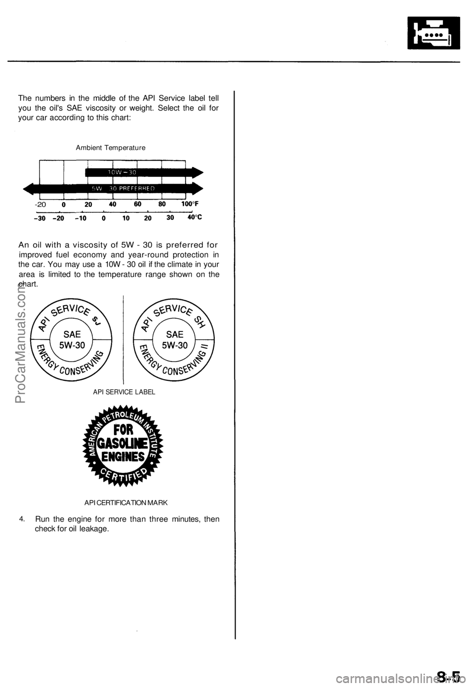
The numbers in the middle of the API Service label tell
you the oil's SAE viscosity or weight. Select the oil for
your car according to this chart:
Ambient Temperature
-20
An oil with a viscosity of 5W - 30 is preferred for
improved fuel economy and year-round protection in
the car. You may use a 10W - 30 oil if the climate in your
area is limited to the temperature range shown on the
chart.
API SERVICE LABEL
4.
API CERTIFICATION MARK
Run the engine for more than three minutes, then
check for oil leakage.ProCarManuals.com
Page 130 of 1771
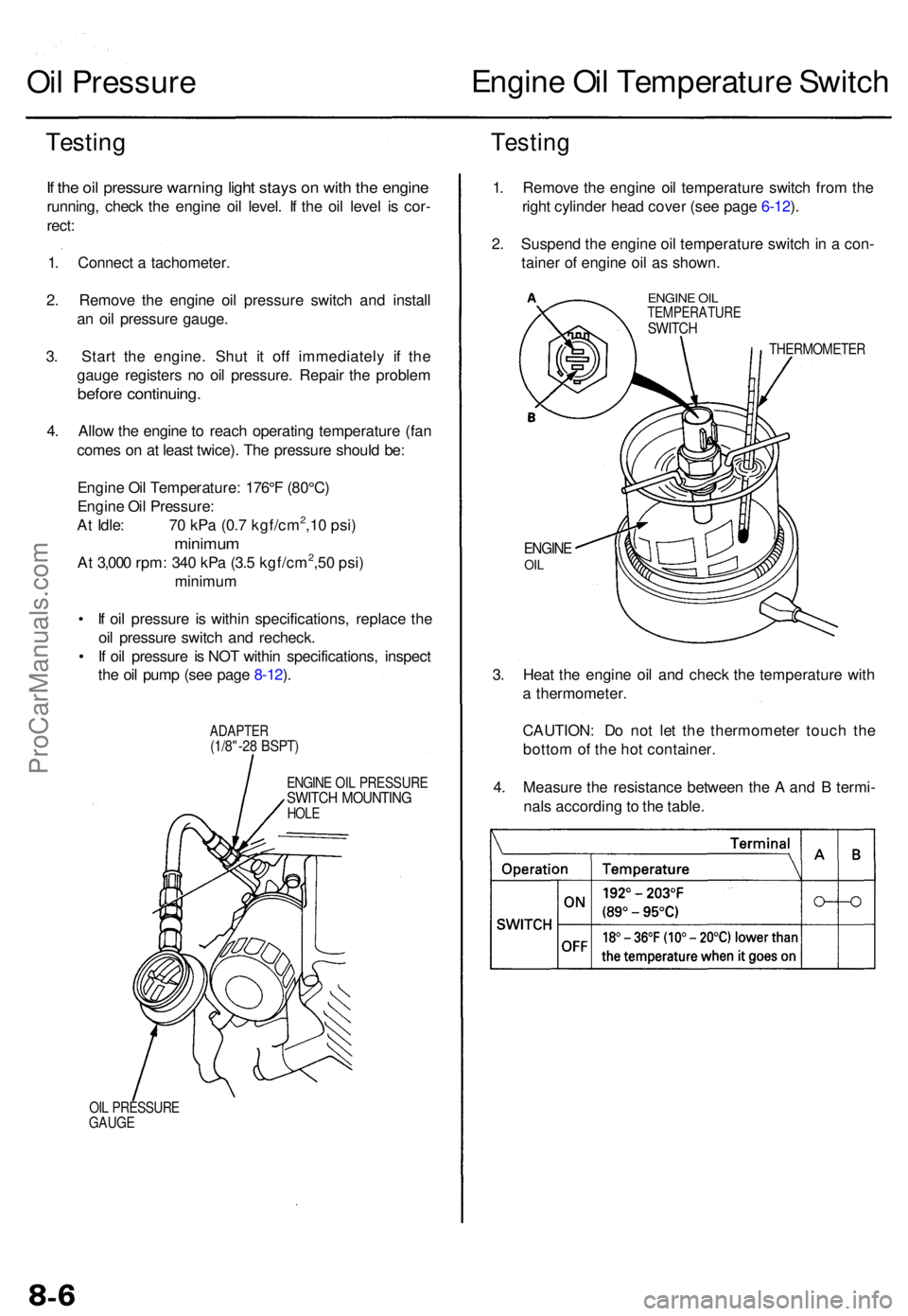
Oil Pressur e Engin
e Oi l Temperatur e Switc h
Testin gTestin g
If th e oi l pressur e warnin g ligh t stay s o n wit h th e engin e
running , chec k th e engin e oi l level . I f th e oi l leve l i s cor -
rect :
1 . Connec t a tachometer .
2 . Remov e th e engin e oi l pressur e switc h an d instal l
a n oi l pressur e gauge .
3 . Star t th e engine . Shu t i t of f immediatel y i f th e
gaug e register s n o oi l pressure . Repai r th e proble m
before continuing .
4. Allo w th e engin e to reac h operatin g temperatur e (fa n
come s o n a t leas t twice) . Th e pressur e shoul d be :
Engin e Oi l Temperature : 176° F (80°C )
Engin e Oi l Pressure :
A t Idle : 7 0 kP a (0. 7 kgf/cm
2,1 0 psi )
minimu m
At 3,00 0 rpm : 34 0 kP a (3. 5 kgf/cm2,5 0 psi )
minimu m
• I f oi l pressur e i s withi n specifications , replac e th e
oi l pressur e switc h an d recheck .
• I f oi l pressur e i s NO T withi n specifications , inspec t
th e oi l pum p (se e pag e 8-12 ).
ADAPTE R(1/8"-28 BSPT )
ENGIN E OI L PRESSUR ESWITCH MOUNTIN GHOLE
OIL PRESSUR E
GAUG E
1. Remov e th e engin e oi l temperatur e switc h fro m th e
righ t cylinde r hea d cove r (se e pag e 6-12 ).
2 . Suspen d th e engin e oi l temperatur e switc h in a con -
taine r o f engin e oi l a s shown .
ENGINE OI LTEMPERATUR ESWITCH
THERMOMETE R
ENGINEOIL
3. Hea t th e engin e oi l an d chec k th e temperatur e wit h
a thermometer .
CAUTION : D o no t le t th e thermomete r touc h th e
botto m of th e ho t container .
4 . Measur e th e resistanc e betwee n th e A an d B termi -
nal s accordin g to th e table .
ProCarManuals.com
Page 440 of 1771
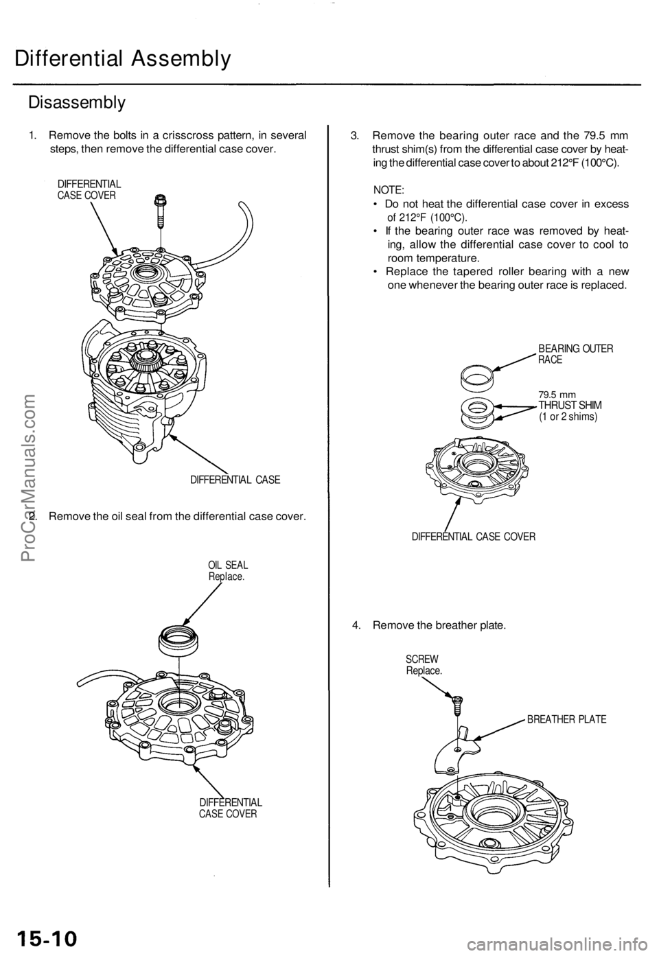
Differential Assembly
Disassembly
1. Remove the bolts in a crisscross pattern, in several
steps, then remove the differential case cover.
DIFFERENTIAL
CASE COVER
DIFFERENTIAL CASE
2. Remove the oil seal from the differential case cover.
OIL SEAL
Replace.
DIFFERENTIAL
CASE COVER
3. Remove the bearing outer race and the 79.5 mm
thrust shim(s) from the differential case cover by heat-
ing the differential case cover to about 212°F (100°C).
NOTE:
• Do not heat the differential case cover in excess
of 212°F (100°C).
• If the bearing outer race was removed by heat-
ing, allow the differential case cover to cool to
room temperature.
• Replace the tapered roller bearing with a new
one whenever the bearing outer race is replaced.
BEARING OUTER
RACE
79.5
mm
THRUST SHIM
(1 or 2 shims)
DIFFERENTIAL CASE COVER
4. Remove the breather plate.
SCREW
Replace.
BREATHER PLATEProCarManuals.com
Page 562 of 1771
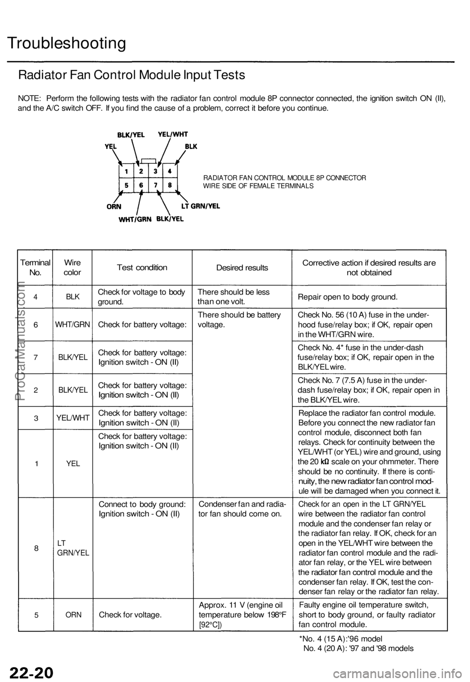
Troubleshooting
Radiator Fan Control Module Input Tests
NOTE: Perform the following tests with the radiator fan control module 8P connector connected, the ignition switch ON (II),
and the A/C switch OFF. If you find the cause of a problem, correct it before you continue.
RADIATOR FAN CONTROL MODULE 8P CONNECTOR
WIRE SIDE OF FEMALE TERMINALS
Terminal
No.
4
6
7
2
3
1
8
5
Wire
color
BLK
WHT/GRN
BLK/YEL
BLK/YEL
YEL/WHT
YEL
LT
GRN/YEL
ORN
Test condition
Check for voltage to body
ground.
Check for battery voltage:
Check for battery voltage:
Ignition switch - ON (II)
Check for battery voltage:
Ignition switch - ON (II)
Check for battery voltage:
Ignition switch - ON (II)
Check for battery voltage:
Ignition switch - ON (II)
Connect to body ground:
Ignition switch - ON (II)
Check for voltage.
Desired results
There should be less
than one volt.
There should be battery
voltage.
Condenser fan and radia-
tor fan should come on.
Approx. 11 V (engine oil
temperature below 198°F
[92°C])
Corrective action if desired results are
not obtained
Repair open to body ground.
Check No. 56 (10 A) fuse in the under-
hood fuse/relay box; if OK, repair open
in the WHT/GRN wire.
Check No. 4* fuse in the under-dash
fuse/relay box; if OK, repair open in the
BLK/YEL wire.
Check No. 7 (7.5 A) fuse in the under-
dash fuse/relay box; if OK, repair open in
the BLK/YEL wire.
Replace the radiator fan control module.
Before you connect the new radiator fan
control module, disconnect both fan
relays. Check for continuity between the
YEL/WHT (or YEL) wire and ground, using
the 20 scale on your ohmmeter. There
should be no continuity. If there is conti-
nuity, the new radiator fan control mod-
ule will be damaged when you connect it.
Check for an open in the LT GRN/YEL
wire between the radiator fan control
module and the condenser fan relay or
the radiator fan relay. If OK, check for an
open in the YEL/WHT wire between the
radiator fan control module and the radi-
ator fan relay, or the YEL wire between
the radiator fan control module and the
condenser fan relay. If OK, test the con-
denser fan relay or the radiator fan relay.
Faulty engine oil temperature switch,
short to body ground, or faulty radiator
fan control module.
*No. 4 (15 A):'96 model
No. 4 (20 A): '97 and '98 modelsProCarManuals.com
Page 800 of 1771
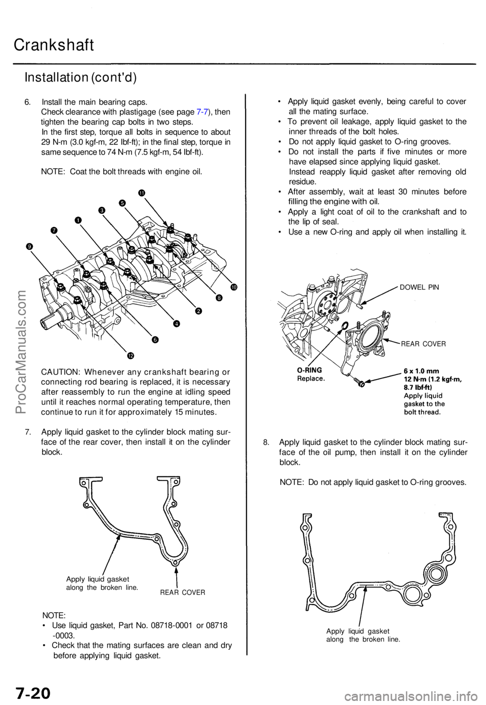
Crankshaft
Installation (cont'd )
6. Instal l th e mai n bearin g caps .
Chec k clearanc e wit h plastigag e (se e pag e 7-7 ), the n
tighte n th e bearin g ca p bolt s i n tw o steps .
I n th e firs t step , torqu e al l bolt s i n sequenc e t o abou t
2 9 N- m (3. 0 kgf-m , 2 2 Ibf-ft) ; i n th e fina l step , torqu e in
sam e sequenc e to 7 4 N- m (7. 5 kgf-m , 5 4 Ibf-ft) .
NOTE : Coa t th e bol t thread s wit h engin e oil .
7.
CAUTION : Wheneve r an y crankshaf t bearin g o r
connectin g ro d bearin g is replaced , i t i s necessar y
afte r reassembl y t o ru n th e engin e a t idlin g spee d
unti l i t reache s norma l operatin g temperature , the n
continu e to ru n it fo r approximatel y 1 5 minutes .
Appl y liqui d gaske t t o th e cylinde r bloc k matin g sur -
fac e o f th e rea r cover , the n instal l i t o n th e cylinde r
block .
Apply liqui d gaske talong th e broke n line .REA R COVE R
NOTE:
• Us e liqui d gasket , Par t No . 0871 8-000 1 o r 0871 8
- 0003 .
• Chec k tha t th e matin g surface s ar e clea n an d dr y
befor e applyin g liqui d gasket .
8.
• Appl y liqui d gaske t evenly , bein g carefu l t o cove r
al l th e matin g surface .
• T o preven t oi l leakage , appl y liqui d gaske t t o th e
inne r thread s o f th e bol t holes .
• D o no t appl y liqui d gaske t t o O-rin g grooves .
• D o no t instal l th e part s i f fiv e minute s o r mor e
hav e elapse d sinc e applyin g liqui d gasket .
Instea d reappl y liqui d gaske t afte r removin g ol d
residue .
• Afte r assembly , wai t a t leas t 3 0 minute s befor e
filling th e engin e wit h oil .
• Appl y a ligh t coa t o f oi l t o th e crankshaf t an d t o
th e li p o f seal .
• Us e a ne w O-rin g an d appl y oi l whe n installin g it .
DOWE L PI N
REA R COVE R
Apply liqui d gaske t t o th e cylinde r bloc k matin g sur -
fac e o f th e oi l pump , the n instal l i t o n th e cylinde r
block .
NOTE : D o no t appl y liqui d gaske t t o O-rin g grooves .
Apply liqui d gaske t
alon g th e broke n line .
ProCarManuals.com