1995 ACURA TL torque
[x] Cancel search: torquePage 54 of 1771
Engine Removal/Installation
Installation
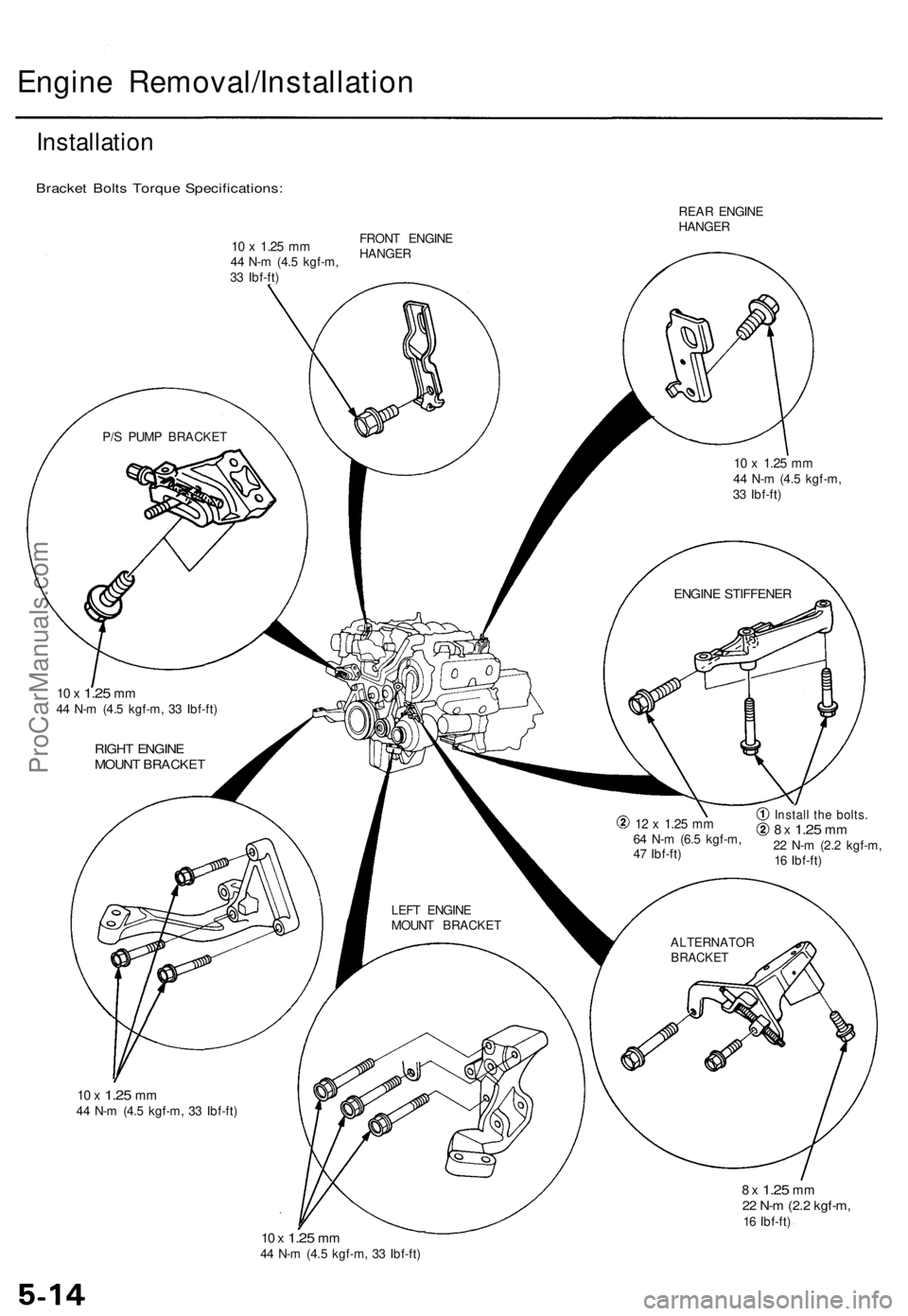
Bracket Bolts Torque Specifications:
REAR ENGINE
HANGER
P/S PUMP BRACKET
10 x
1.25
mm
44 N-m (4.5 kgf-m,
33 Ibf-ft)
ENGINE STIFFENER
10 x
1.25
mm
44 N-m (4.5 kgf-m, 33 Ibf-ft)
RIGHT ENGINE
MOUNT BRACKET
LEFT ENGINE
MOUNT BRACKET
12 x
1.25
mm
64 N-m (6.5 kgf-m,
47 Ibf-ft)
Install the bolts.
8 x
1.25
mm
22 N-m (2.2 kgf-m,
16 Ibf-ft)
ALTERNATOR
BRACKET
10 x
1.25
mm
44 N-m (4.5 kgf-m, 33 Ibf-ft)
8 x
1.25
mm
22 N-m (2.2 kgf-m,
16 Ibf-ft)
10 x
1.25
mm
44 N-m (4.5 kgf-m, 33 Ibf-ft)
10 x
1.25
mm
44 N-m (4.5 kgf-m,
33 Ibf-ft)
FRONT ENGINE
HANGERProCarManuals.com
Page 58 of 1771
Engine Removal/Installation
Installation (cont'd)
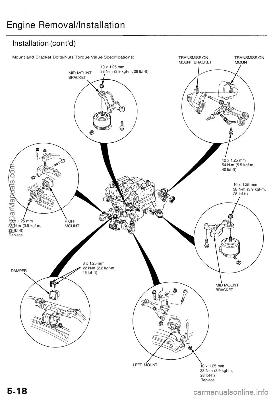
Mount and Bracket Bolts/Nuts Torque Value Specifications:
TRANSMISSION
MOUNT BRACKET
TRANSMISSION
MOUNT
12 x
1.25
mm
54 N-m (5.5 kgf-m,
40 Ibf-ft)
10 x
1.25
mm
38 N-m (3.9 kgf-m,
28 Ibf-ft)
10 x
1.25
mm
38 N-m (3.9 kgf-m,
28 Ibf-ft)
Replace.
RIGHT
MOUNT
DAMPER
8 x
1.25
mm
' 22 N-m (2.2 kgf-m,
16 Ibf-ft)
MID MOUNT
BRACKET
LEFT MOUNT
10 x
1.25
mm
38 N-m (3.9 kgf-m,
28 Ibf-ft)
Replace.
MID MOUNT
BRACKET
10 x
1.25
mm
38 N-m (3.9 kgf-m, 28 Ibf-ft)ProCarManuals.com
Page 82 of 1771
Camshaft
Inspection
NOTE:
Do not rotate the camshaft during inspection.
Remove the rocker arms and rocker shafts.
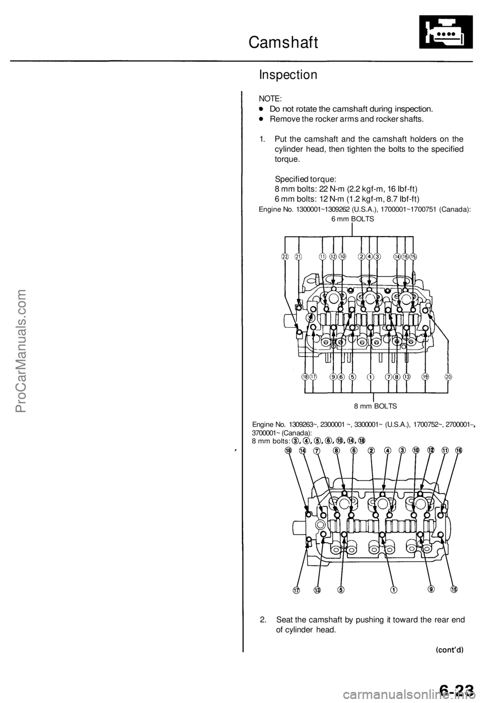
1. Put the camshaft and the camshaft holders on the
cylinder head, then tighten the bolts to the specified
torque.
Specified torque:
8 mm bolts: 22 N-m (2.2 kgf-m, 16 Ibf-ft)
6 mm bolts: 12 N-m (1.2 kgf-m, 8.7 Ibf-ft)
Engine No. 1300001~1309262 (U.S.A.), 1700001~1700751 (Canada):
6 mm BOLTS
8 mm BOLTS
Engine No. 1309263~, 2300001 ~, 3300001~ (U.S.A.), 1700752~, 2700001-
3700001~ (Canada):
8 mm bolts:
2. Seat the camshaft by pushing it toward the rear end
of cylinder head.ProCarManuals.com
Page 83 of 1771
Camshaft
Inspection (cont'd)
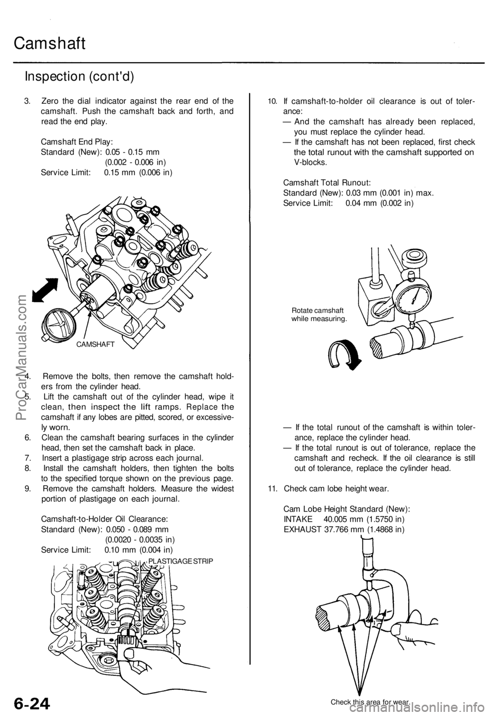
3. Zero the dial indicator against the rear end of the
camshaft. Push the camshaft back and forth, and
read the end play.
Camshaft End Play:
Standard (New): 0.05 - 0.15 mm
(0.002 - 0.006 in)
Service Limit: 0.15 mm (0.006 in)
4. Remove the bolts, then remove the camshaft hold-
ers from the cylinder head.
5. Lift the camshaft out of the cylinder head, wipe it
clean,
then
inspect
the
lift
ramps.
Replace
the
camshaft if any lobes are pitted, scored, or excessive-
ly worn.
6. Clean the camshaft bearing surfaces in the cylinder
head, then set the camshaft back in place.
7. Insert a plastigage strip across each journal.
8. Install the camshaft holders, then tighten the bolts
to the specified torque shown on the previous page.
9. Remove the camshaft holders. Measure the widest
portion of plastigage on each journal.
Camshaft-to-Holder Oil Clearance:
Standard (New): 0.050 - 0.089 mm
(0.0020 - 0.0035 in)
Service Limit: 0.10 mm (0.004 in)
PLASTIGAGE STRIP
10.
If camshaft-to-holder oil clearance is out of toler-
ance:
— And the camshaft has already been replaced,
you must replace the cylinder head.
— If the camshaft has not been replaced, first check
the total runout with the camshaft supported on
V-blocks.
Camshaft Total Runout:
Standard (New): 0.03 mm (0.001 in) max.
Service Limit: 0.04 mm (0.002 in)
Rotate camshaft
while measuring.
— If the total runout of the camshaft is within toler-
ance, replace the cylinder head.
— If the total runout is out of tolerance, replace the
camshaft and recheck. If the oil clearance is still
out of tolerance, replace the cylinder head.
11. Check cam lobe height wear.
Cam Lobe Height Standard (New):
INTAKE 40.005 mm (1.5750 in)
EXHAUST 37.766 mm (1.4868 in)
Check this area for wear.
CAMSHAFTProCarManuals.com
Page 95 of 1771
Camshafts/Rocker Arms and Camshaft Seals
Installation
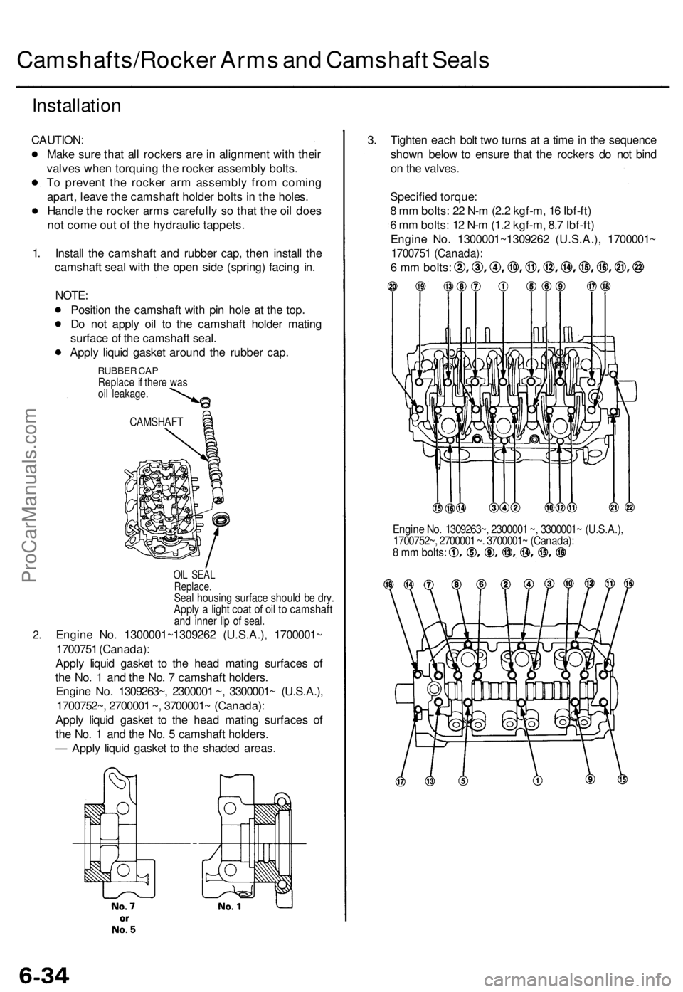
CAUTION:
Make sure that all rockers are in alignment with their
valves when torquing the rocker assembly bolts.
To prevent the rocker arm assembly from coming
apart, leave the camshaft holder bolts in the holes.
Handle the rocker arms carefully so that the oil does
not come out of the hydraulic tappets.
1.
2.
Install the camshaft and rubber cap, then install the
camshaft seal with the open side (spring) facing in.
NOTE:
Position the camshaft with pin hole at the top.
Do not apply oil to the camshaft holder mating
surface of the camshaft seal.
Apply liquid gasket around the rubber cap.
RUBBER CAP
Replace if there was
oil leakage.
CAMSHAFT
OIL SEAL
Replace.
Seal housing surface should be dry.
Apply a light coat of oil to camshaft
and inner lip of seal.
Engine No. 1300001~1309262 (U.S.A.), 1700001~
1700751 (Canada):
Apply liquid gasket to the head mating surfaces of
the No. 1 and the No. 7 camshaft holders.
Engine No. 1309263~, 2300001 ~, 3300001~ (U.S.A.),
1700752~, 2700001 ~, 3700001~ (Canada):
Apply liquid gasket to the head mating surfaces of
the No. 1 and the No. 5 camshaft holders.
— Apply liquid gasket to the shaded areas.
3. Tighten each bolt two turns at a time in the sequence
shown below to ensure that the rockers do not bind
on the valves.
Specified torque:
8 mm bolts: 22 N-m (2.2 kgf-m, 16 Ibf-ft)
6 mm bolts: 12 N-m (1.2 kgf-m, 8.7 Ibf-ft)
Engine No. 1300001~1309262 (U.S.A.), 1700001~
1700751 (Canada):
6 mm bolts:
Engine No. 1309263~, 2300001 ~, 3300001~ (U.S.A.),
1700752~, 2700001 ~. 3700001~ (Canada):
8 mm bolts:ProCarManuals.com
Page 96 of 1771
Cylinder Heads
Installation
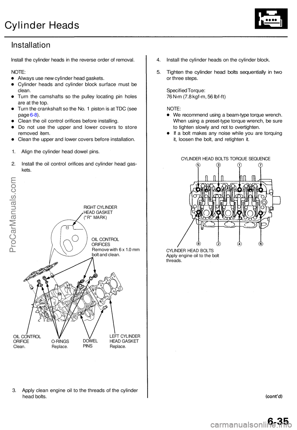
Install th e cylinde r head s in th e revers e orde r o f removal .
NOTE:
Alway s us e ne w cylinde r hea d gaskets .
Cylinde r head s an d cylinde r bloc k surfac e mus t b e
clean .
Turn th e camshaft s s o th e pulle y locatin g pi n hole s
are a t th e top .
Turn th e crankshaf t s o th e No . 1 pisto n is a t TD C (se e
pag e 6-8 ).
Clea n th e oi l contro l orifice s befor e installing .
D o no t us e th e uppe r an d lowe r cover s t o stor e
remove d item .
Clea n th e uppe r an d lowe r cover s befor e installation .
1 . Alig n th e cylinde r hea d dowe l pins .
2 . Instal l th e oi l contro l orifice s an d cylinde r hea d gas -
kets.
RIGH T CYLINDE RHEAD GASKE T("R" MARK )
OIL CONTRO LORIFICESRemove wit h 6 x 1. 0 m m
bol t an d clean .
OIL CONTRO LORIFICEClean.O-RING SReplace .
DOWELPINS
LEF T CYLINDE RHEAD GASKE TReplace.
3. Appl y clea n engin e oi l t o th e thread s o f th e cylinde r
hea d bolts . 4
. Instal l th e cylinde r head s o n th e cylinde r block .
5. Tighte n th e cylinde r hea d bolt s sequentiall y in tw o
or thre e steps .
Specifie d Torque :
7 6 N- m (7. 8 kgf-m , 5 6 Ibf-ft )
NOTE :
We recommen d usin g a beam-typ e torqu e wrench .
Whe n usin g a preset-typ e torqu e wrench , b e sur e
t o tighte n slowl y an d no t t o overtighten .
I f a bol t make s an y nois e whil e yo u ar e torquin g
it , loose n th e bolt , an d retighte n it .
CYLINDE R HEA D BOLT S TORQU E SEQUENC E
CYLINDER HEA D BOLT SApply engin e oi l t o th e bol tthreads .
ProCarManuals.com
Page 105 of 1771
Connecting Rod Bearings
Clearance
Selection
1. Remove the connecting rod cap and bearing half.
2. Clean the crankshaft rod journal and bearing half
with a clean shop towel.
3. Place a plastigage strip across the rod journal.
4. Reinstall the bearing half and cap, and torque the
nuts to 44 N-m (4.5 kgf-m, 33 Ibf-ft).
NOTE: Do not rotate the crankshaft during inspec-
tion.
5. Remove the rod cap and bearing half and measure
the widest part of the plastigage.
Connecting Rod Bearing-to-Journal Oil Clearance:
Standard (New): 0.022 - 0.046 mm
(0.0009 - 0.0018 in)
Service Limit: 0.05 mm (0.002 in)
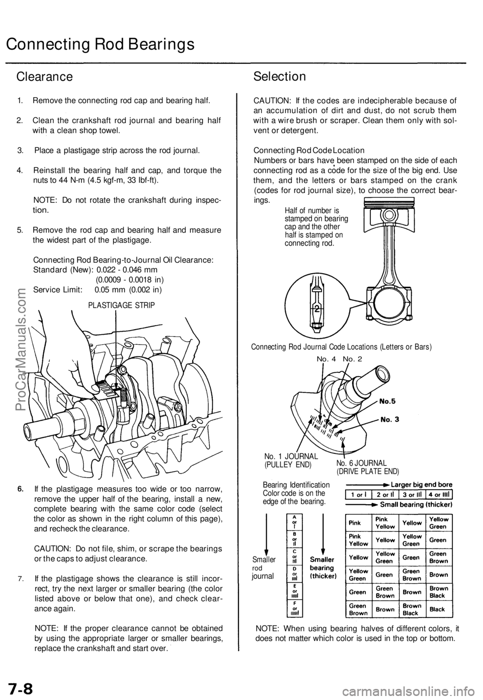
PLASTIGAGE STRIP
7.
If the plastigage measures too wide or too narrow,
remove the upper half of the bearing, install a new,
complete bearing with the same color code (select
the color as shown in the right column of this page),
and recheck the clearance.
CAUTION: Do not file, shim, or scrape the bearings
or the caps to adjust clearance.
If the plastigage shows the clearance is still incor-
rect, try the next larger or smaller bearing (the color
listed above or below that one), and check clear-
ance again.
NOTE: If the proper clearance cannot be obtained
by using the appropriate larger or smaller bearings,
replace the crankshaft and start over.
CAUTION: If the codes are indecipherable because of
an accumulation of dirt and dust, do not scrub them
with a wire brush or scraper. Clean them only with sol-
vent or detergent.
Connecting Rod Code Location
Numbers or bars have been stamped on the side of each
connecting rod as a code for the size of the big end. Use
them, and the letters or bars stamped on the crank
(codes for rod journal size), to choose the correct bear-
ings.
Half of number is
stamped on bearing
cap and the other
half is stamped on
connecting rod.
Connecting Rod Journal Code Locations (Letters or Bars)
No. 4 No. 2
No. 1 JOURNAL
(PULLEY END)
Bearing Identification
Color code is on the
edge of the bearing.
No. 6 JOURNAL
(DRIVE PLATE END)
Smaller
rod
journal
NOTE: When using bearing halves of different colors, it
does not matter which color is used in the top or bottom.ProCarManuals.com
Page 116 of 1771
Pistons
Installation
Before installing the piston, apply a coat of engine
oil to the ring grooves and cylinder bores.
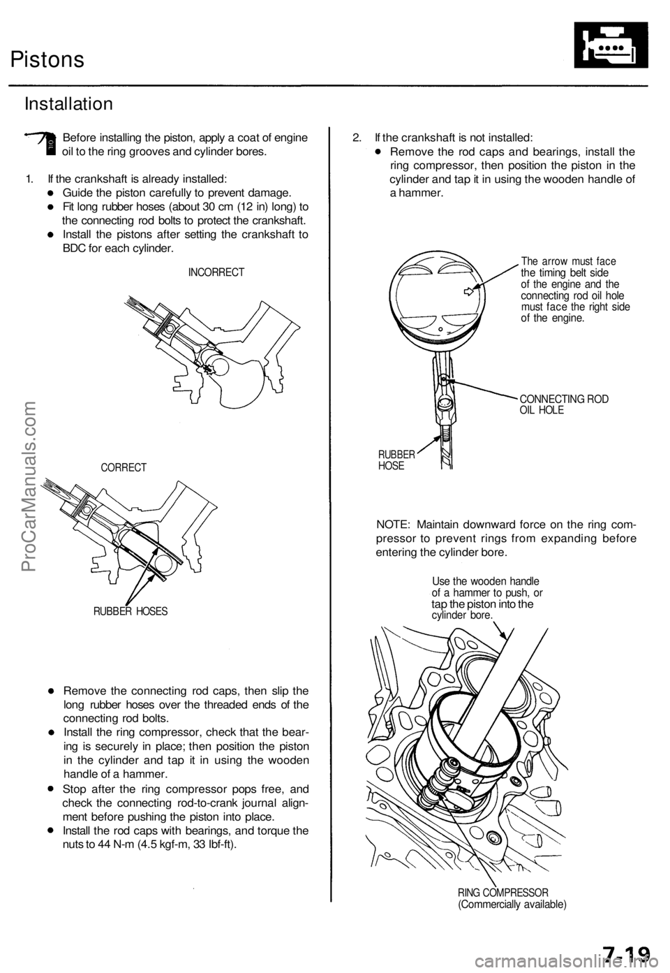
1. If the crankshaft is already installed:
Guide the piston carefully to prevent damage.
Fit long rubber hoses (about 30 cm (12 in) long) to
the connecting rod bolts to protect the crankshaft.
Install the pistons after setting the crankshaft to
BDC for each cylinder.
INCORRECT
CORRECT
RUBBER HOSES
Remove the connecting rod caps, then slip the
long rubber hoses over the threaded ends of the
connecting rod bolts.
Install the ring compressor, check that the bear-
ing is securely in place; then position the piston
in the cylinder and tap it in using the wooden
handle of a hammer.
Stop after the ring compressor pops free, and
check the connecting rod-to-crank journal align-
ment before pushing the piston into place.
Install the rod caps with bearings, and torque the
nuts to 44 N-m (4.5 kgf-m, 33 Ibf-ft).
2. If the crankshaft is not installed:
Remove the rod caps and bearings, install the
ring compressor, then position the piston in the
cylinder and tap it in using the wooden handle of
a hammer.
The arrow must face
the timing belt side
of the engine and the
connecting rod oil hole
must face the right side
of the engine.
CONNECTING ROD
OIL HOLE
RUBBER
HOSE
NOTE: Maintain downward force on the ring com-
pressor to prevent rings from expanding before
entering the cylinder bore.
Use the wooden handle
of a hammer to push, or
tap the piston into the
cylinder bore.
RING COMPRESSOR
(Commercially available)ProCarManuals.com