1995 ACURA TL torque
[x] Cancel search: torquePage 120 of 1771
Crankshaft
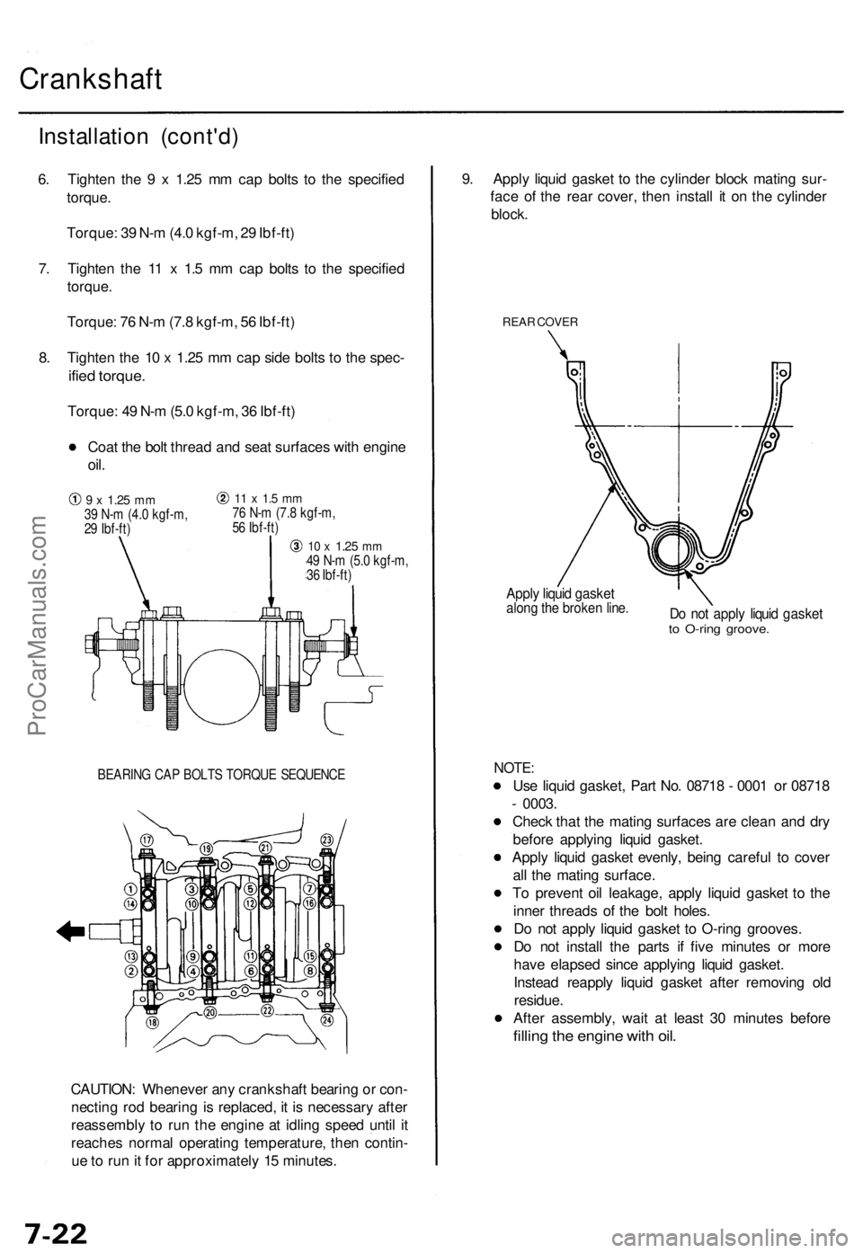
BEARING CAP BOLTS TORQUE SEQUENCE
CAUTION: Whenever any crankshaft bearing or con-
necting rod bearing is replaced, it is necessary after
reassembly to run the engine at idling speed until it
reaches normal operating temperature, then contin-
ue to run it for approximately 15 minutes.
9. Apply liquid gasket to the cylinder block mating sur-
face of the rear cover, then install it on the cylinder
block.
REAR COVER
Apply liquid gasket
along the broken line.
Do not apply liquid gasket
to O-ring groove.
NOTE:
Use liquid gasket, Part No. 08718 - 0001 or 08718
- 0003.
Check that the mating surfaces are clean and dry
before applying liquid gasket.
Apply liquid gasket evenly, being careful to cover
all the mating surface.
To prevent oil leakage, apply liquid gasket to the
inner threads of the bolt holes.
Do not apply liquid gasket to O-ring grooves.
Do not install the parts if five minutes or more
have elapsed since applying liquid gasket.
Instead reapply liquid gasket after removing old
residue.
After assembly, wait at least 30 minutes before
filling the engine with oil.
Installation (cont'd)
6. Tighten the 9 x 1.25 mm cap bolts to the specified
torque.
Torque: 39 N-m (4.0 kgf-m, 29 Ibf-ft)
7. Tighten the 11 x 1.5 mm cap bolts to the specified
torque.
Torque: 76 N-m (7.8 kgf-m, 56 Ibf-ft)
8. Tighten the 10 x 1.25 mm cap side bolts to the spec-
ified torque.
Torque: 49 N-m (5.0 kgf-m, 36 Ibf-ft)
Coat the bolt thread and seat surfaces with engine
oil.
9 x
1.25
mm
39 N-m (4.0 kgf-m,
29 Ibf-ft)
11 x 1.5 mm
76 N-m (7.8 kgf-m,
56 Ibf-ft)
10 x
1.25
mm
49 N-m (5.0 kgf-m,
36 Ibf-ft)ProCarManuals.com
Page 129 of 1771
Oil Filte r
Replacemen t
CAUTION: Loose n th e engin e oi l filte r carefull y whil e
th e engin e is hot , th e ho t oi l ma y caus e scalding .
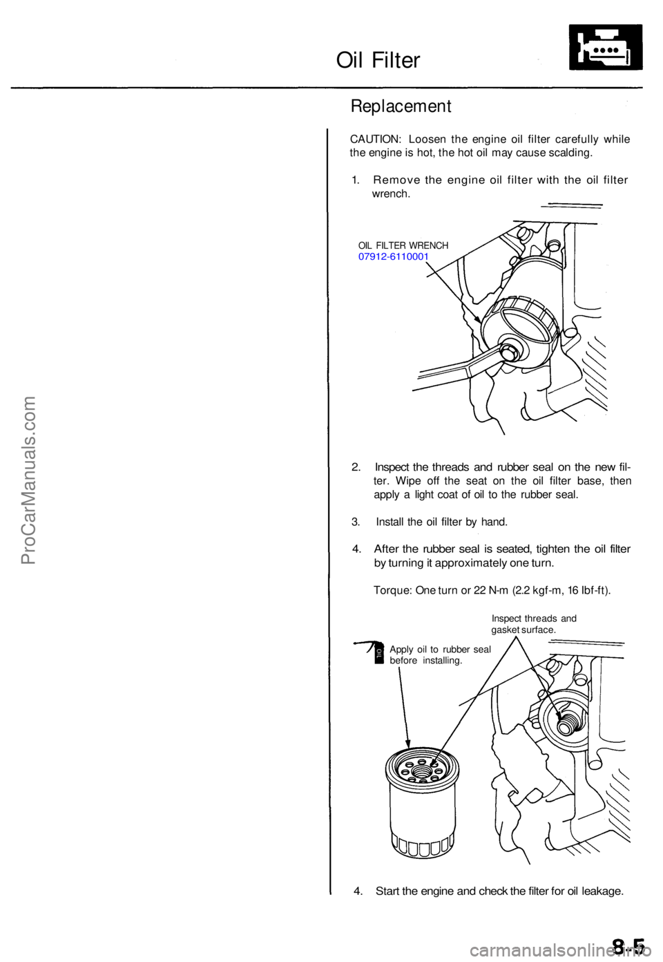
1. Remov e th e engin e oi l filte r wit h th e oi l filte r
wrench .
OIL FILTE R WRENC H07912-611000 1
2. Inspec t th e thread s an d rubbe r sea l o n th e ne w fil -
ter . Wip e of f th e sea t o n th e oi l filte r base , the n
appl y a ligh t coa t o f oi l t o th e rubbe r seal .
3 . Instal l th e oi l filte r b y hand .
4. Afte r th e rubbe r sea l i s seated , tighte n th e oi l filte r
by turnin g it approximatel y on e turn .
Torque : On e tur n o r 2 2 N- m (2. 2 kgf-m , 1 6 Ibf-ft) .
Inspec t thread s an d
gaske t surface .
Appl y oi l t o rubbe r sea l
befor e installing .
4. Star t th e engin e an d chec k th e filte r fo r oi l leakage .
ProCarManuals.com
Page 200 of 1771
PGM-FI System
System Description (cont'd)
3. Fuel Cut-off Control
During deceleration with the throttle valve closed, current to the fuel injectors is cut off to improve fuel economy at
speeds over 1,000 rpm.
Fuel cut-off action also takes place when engine speed exceeds 6,500 rpm, regardless of the position of the throttle
valve, to protect the engine from over-revving.
4. A/C Compressor Clutch Relay .
When the PCM receives a demand for cooling from the air conditioning system, it delays the compressor from being
energized, and enriches the mixture to assure a smooth transition to the A/C mode.
5. Evaporative Emission (EVAP) Purge Control Solenoid Valve
'96 model: When the engine coolant temperature is below 158°F (70°C), the PCM controls the EVAP purge control
solenoid valve which cuts vacuum to the EVAP purge control canister diaphragm.
'97 - 98 models: When the engine coolant temperature is above 99°F (37°C), the PCM controls the EVAP purge control
solenoid valve which controls vacuum to the EVAP purge control canister.
6. Intake Air Bypass (IAB) Low Control Solenoid Valve, Intake Air Bypass (IAB) High Control Solenoid Valve
When engine speed is below 3,350 rpm, the IAB High Control Solenoid Valve and IAB Low Control Solenoid Valve are
activated by a signal from the PCM. Intake air flows through a long chamber path, increasing torque at low RPM.
When engine speed is 3,350 - 3,950 rpm, the IAB Low Control Solenoid Valve is deactivated by the PCM. Intake air
flows through a short chamber path, increasing mid-range torque.
When the engine rpm is above 3,950 rpm, the IAB Low Control Solenoid Valve and IAB High Control Solenoid Valve are
deactivated by the PCM. This creates a very short intake path and increases high-speed torque.
7. Exhaust Gas Recirculation (EGR) Control Solenoid Valve
When the EGR is required for control of oxides of nitrogen (NOx) emissions, the PCM controls the EGR control solenoid
valve which supplies regulated vacuum to the EGR valve.
ECM Fail-safe/Back-up Functions
1. Fail-safe Function
When an abnormality occurs in a signal from a sensor, the PCM ignores that signal and assumes a pre-programmed
value for that sensor that allows the engine to continue to run.
2. Back-up Function
When an abnormality occurs in the PCM itself, the fuel injectors are controlled by a back-up circuit independent of the
system in order to permit minimal driving.
3. Self-diagnosis Function [Malfunction Indicator Lamp (MIL)]
When an abnormality occurs in a signal from a sensor, the PCM supplies ground for the MIL and stores the DTC in
erasable memory. When the ignition is initially turned on, the PCM supplies ground for the MIL for two seconds to
check the MIL bulb condition.
4. Two Driving Cycle Detection Method
To prevent false indications, the two driving cycle detection method is used for the H02S, fuel metering-related, idle
control system, ECT sensor, EGR system, TWC, EVAP control system and other self-diagnostic functions. When an
abnormality occurs, the PCM stores it in its memory. When the same abnormality recurs after the ignition switch is
turned OFF and ON (II) again, the PCM informs the driver by lighting the MIL.
However, to ease troubleshooting, this function is cancelled when you short the service check connector. The MIL will
then blink immediately when an abnormality occurs.ProCarManuals.com
Page 257 of 1771
Description
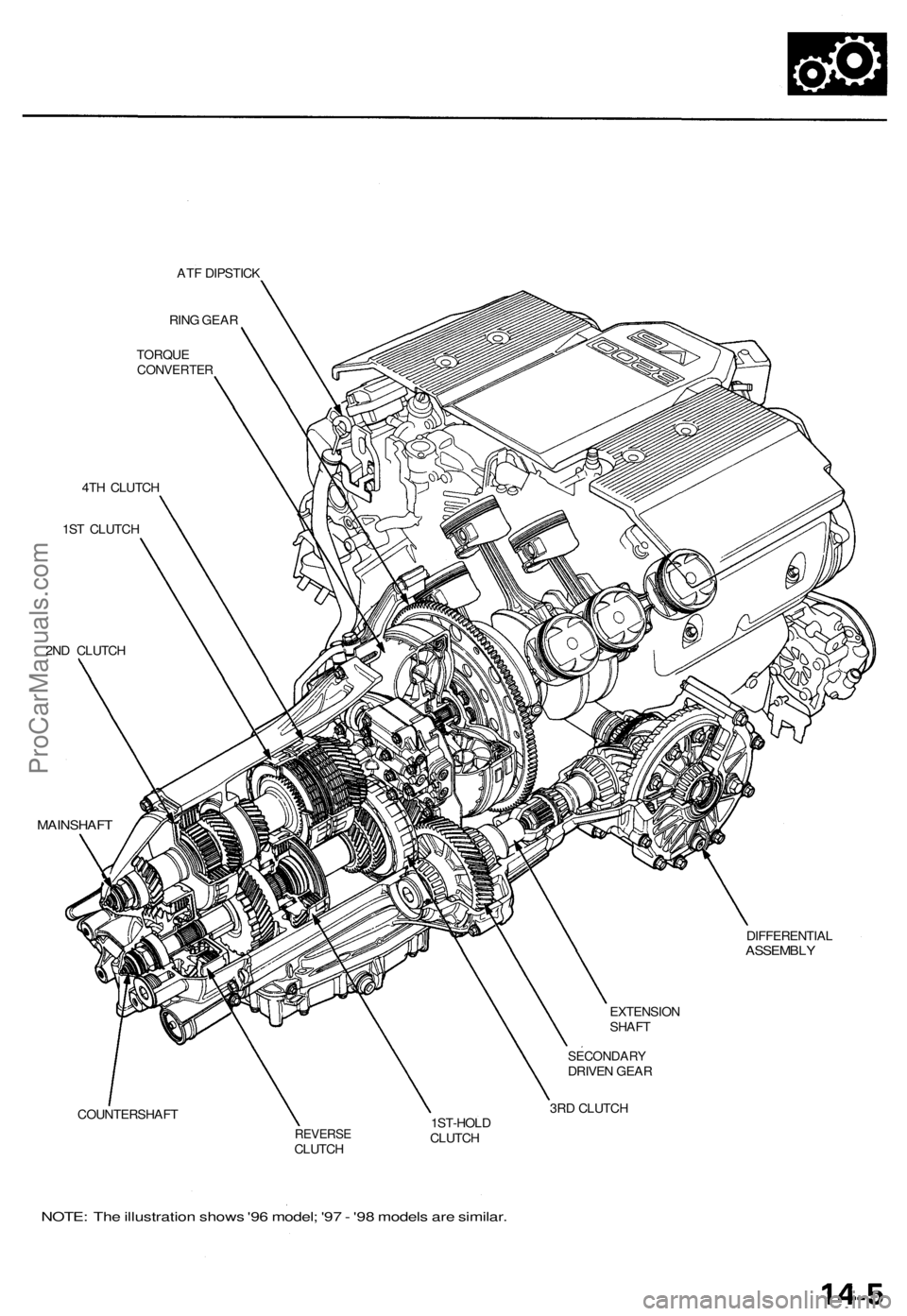
The automatic transmission is a combination of a 3-element torque converter and a dual-shaft electronically controlled
automatic transmission which provides 4 speeds forward and 1 reverse. The entire unit is positioned in line with the engine.
Torque Converter, Gears and Clutches
The torque converter consists of a pump, turbine, and stator, assembled in a single unit. They are connected to the engine
crankshaft so they turn together as a unit as the engine turns. Around the outside of the drive plate is a ring gear which
meshes with the starter pinion when the engine is being started.
The entire torque converter assembly serves as a flywheel while transmitting power to the transmission mainshaft.
The transmission has two parallel shafts: the mainshaft and the countershaft. The mainshaft is in line with the engine
crankshaft. The mainshaft includes the 1st, 4th and 2nd clutches and gears for 4th, 1st, 2nd and reverse (3rd gear is integral
with the mainshaft). The countershaft includes the 3rd, 1st-hold and reverse clutches, and gears for 3rd, 4th, 1st, 2nd,
reverse and parking. The secondary drive gear is integrated with the countershaft. The gears on the mainshaft are in con-
stant mesh with those on the countershaft. When certain combinations of gears in the transmission are engaged by clutch-
positions.
and
es, power is transmitted from the mainshaft to the countershaft to provide
Electronic Control
The electronic control system consists of a Powertrain Control Module (PCM), sensors, a linear solenoid and four solenoid
valves. Shifting and lock-up are electronically controlled for comfortable driving under all conditions.
The PCM is located below the dashboard, under the front lower panel on the passenger's side.
Hydraulic Control
The lower valve body assembly includes the main valve body, the secondary valve body, the throttle valve body, the lin-
ear solenoid, the shift control solenoid valves and the ATF passage body. They are bolted on the lower part of the trans-
mission housing. The regulator valve body, the ATF pump body, and the accumulator body are bolted to the torque con-
verter housing.
The main valve body on '96 model contains the manual valve, the 1-2 shift valve, the 2-3 shift valve, the 3-4 shift valve, the
4-3 kick-down valve and the Clutch Pressure Control (CPC) valve. The main valve body on '97 model contains the manual
valve, the 1-2 shift valve, the 2-3 shift valve, the 3-4 shift valve, the 4-3 kick-down valve and the main orifice control valve.
The secondary valve body on '96 model contains the 3-4 orifice control valve, the 4-3 shift timing valve, the modulator valve
and the accumulator pistons.The secondary valve body on '97 model contains the 3-4 orifice control valve, the 4-3 shift tim-
ing valve, the line pressure control valve, the modulator valve and the accumulator pistons. The throttle valve body
includes the throttle valve which is bolted onto the secondary valve body. The linear solenoid is joined to the throttle valve
body. The regulator valve body contains the regulator valve, the lock-up shift valve and the cooler relief valve. Fluid from
the regulator passes through the manual valve to the various control valves. The ATF pump body contains the lock-up tim-
ing valve, the lock-up control valve and the relief valve. The torque converter check valve is located in the torque converter
housing under the ATF pump body. The accumulator body contains the accumulator pistons. The reverse accumulator and
the 1st-hold accumulator pistons are assembled in the rear cover.
The 1st, 1st-hold, 2nd and reverse clutches receive fluid from their respective feed pipes, and the 3rd and 4th clutches
receive fluid from the internal hydraulic circuit.
Shift Control Mechanism
Input from various sensors located throughout the vehicle determines which shift control solenoid valve the PCM will acti-
vate. Activating a shift control solenoid valve changes modulator pressure, causing a shift valve to move. This pressurizes a
line to one of the clutches, engaging the clutch and its corresponding gear.
er through a fluid passage, causing the lock-up piston to be held against the torque converter cover. As this takes place, the
mainshaft rotates at the same speed as the engine crankshaft. Together with hydraulic control, the PCM optimizes the tim-
ing of the lock-up mechanism. The lock-up valves control the range of lock-up according to lock-up control solenoid valves
A and B, and throttle valve. When lock-up control solenoid valves A and B activate, modulator pressure changes. The lock-
up control solenoid valves A and B are mounted on the torque converter housing, and are controlled by the PCM.
(cont'd)
Lock-up Mechanism
In
position, in 2nd, 3rd, and 4th, and
position in 3rd, pressurized fluid is drained from the back of the torque convert-ProCarManuals.com
Page 259 of 1771
ATF DIPSTICK
RING GEAR
TORQUE
CONVERTER
4TH CLUTCH
1ST CLUTCH
2ND CLUTCH
MAINSHAFT
COUNTERSHAFT
EXTENSION
SHAFT
SECONDARY
DRIVEN GEAR
3RD CLUTCH
REVERSE
CLUTCH
1ST-HOLD
CLUTCH
DIFFERENTIAL
ASSEMBLY
NOTE: The illustration shows '96 model; '97 - '98 models are similar.ProCarManuals.com
Page 264 of 1771
Description
Power Flow (cont'd)
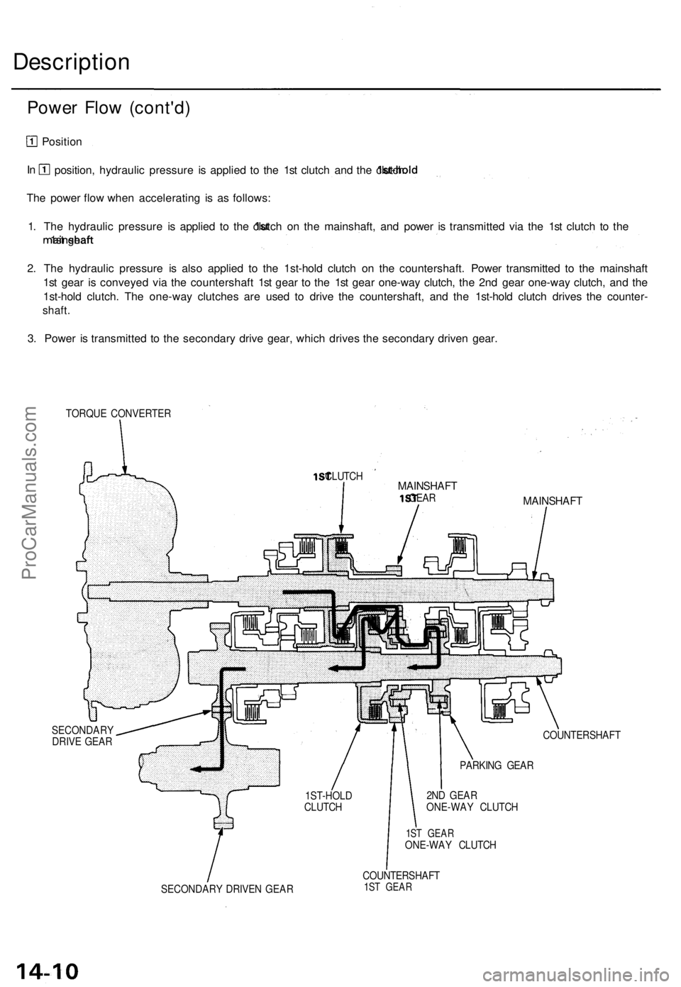
Position
position, hydraulic pressure is applied to the 1st clutch and the
1st-hold
clutch.
The power flow when accelerating is as follows:
1. The hydraulic pressure is applied to the
1st
clutch on the mainshaft, and power is transmitted via the 1st clutch to the
mainshaft
1st gear.
2. The hydraulic pressure is also applied to the 1st-hold clutch on the countershaft. Power transmitted to the mainshaft
1st gear is conveyed via the countershaft 1st gear to the 1st gear one-way clutch, the 2nd gear one-way clutch, and the
1st-hold clutch. The one-way clutches are used to drive the countershaft, and the 1st-hold clutch drives the counter-
shaft.
3. Power is transmitted to the secondary drive gear, which drives the secondary driven gear.
TORQUE CONVERTER
1ST
CLUTCH
MAINSHAFT
1ST
GEAR
SECONDARY
DRIVE GEAR
MAINSHAFT
COUNTERSHAFT
2ND GEAR
ONE-WAY CLUTCH
1ST GEAR
ONE-WAY CLUTCH
SECONDARY DRIVEN GEAR
COUNTERSHAFT
1ST GEAR
In
1ST-HOLD
CLUTCH
PARKING GEARProCarManuals.com
Page 265 of 1771
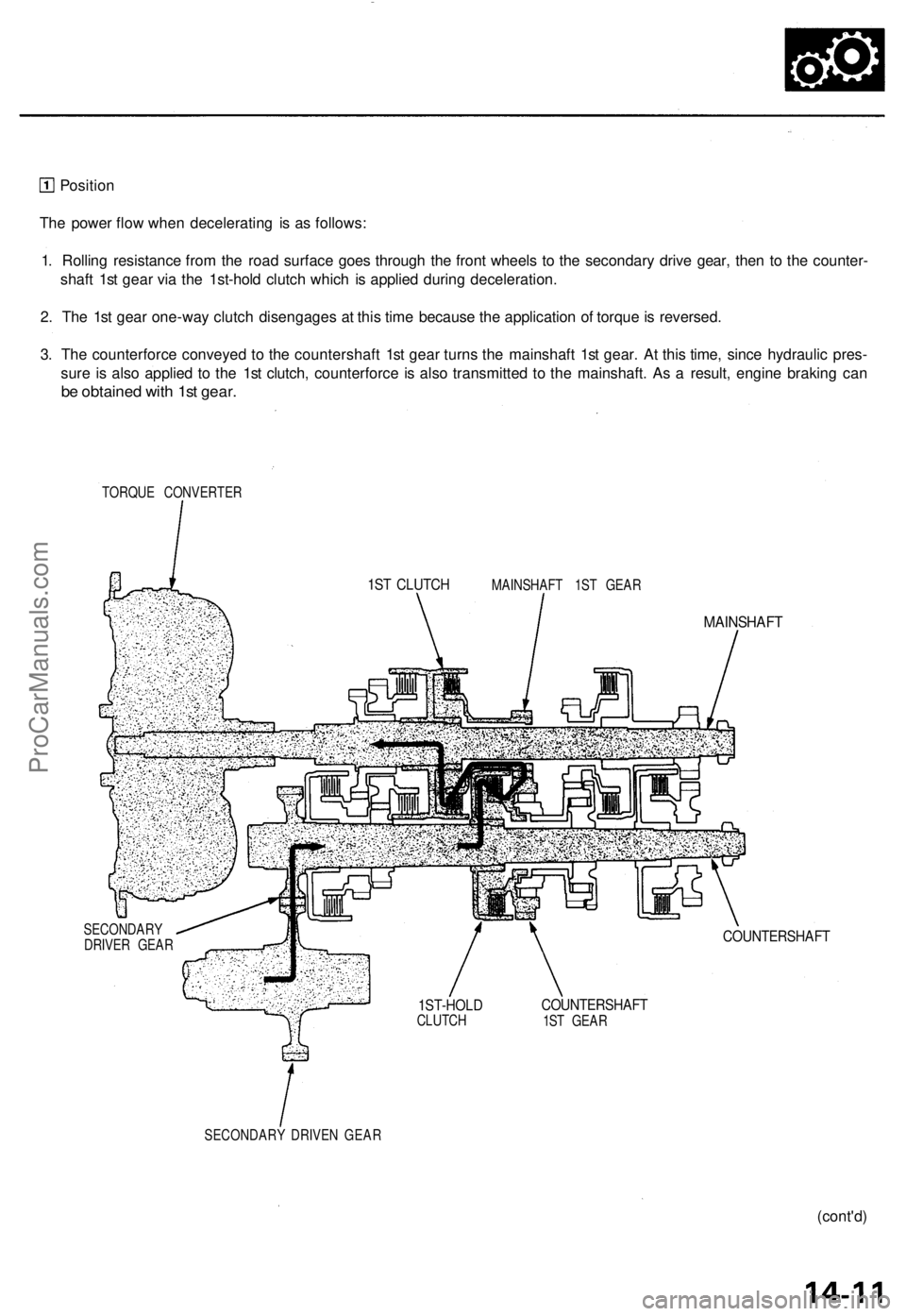
Position
The power flow when decelerating is as follows:
1. Rolling resistance from the road surface goes through the front wheels to the secondary drive gear, then to the counter-
shaft 1st gear via the 1st-hold clutch which is applied during deceleration.
2. The 1st gear one-way clutch disengages at this time because the application of torque is reversed.
3. The counterforce conveyed to the countershaft 1st gear turns the mainshaft 1st gear. At this time, since hydraulic pres-
sure is also applied to the 1st clutch, counterforce is also transmitted to the mainshaft. As a result, engine braking can
be obtained with 1st gear.
TORQUE CONVERTER
MAINSHAFT 1ST GEAR
MAINSHAFT
SECONDARY
DRIVER GEAR
COUNTERSHAFT
COUNTERSHAFT
1ST GEAR
SECONDARY DRIVEN GEAR
(cont'd)
1ST CLUTCH
1ST-HOLD
CLUTCHProCarManuals.com
Page 266 of 1771
Description
Power Flow (cont'd)
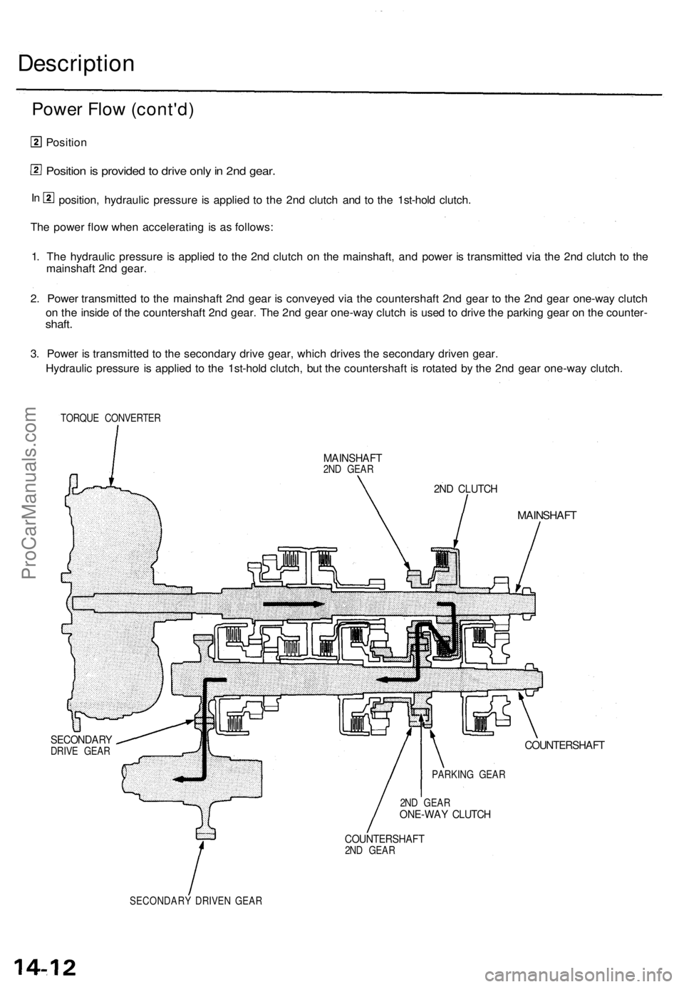
Position
Position is provided to drive only in 2nd gear.
position, hydraulic pressure is applied to the 2nd clutch and to the 1st-hold clutch.
The power flow when accelerating is as follows:
1. The hydraulic pressure is applied to the 2nd clutch on the mainshaft, and power is transmitted via the 2nd clutch to the
mainshaft 2nd gear.
2. Power transmitted to the mainshaft 2nd gear is conveyed via the countershaft 2nd gear to the 2nd gear one-way clutch
on the inside of the countershaft 2nd gear. The 2nd gear one-way clutch is used to drive the parking gear on the counter-
shaft.
3. Power is transmitted to the secondary drive gear, which drives the secondary driven gear.
Hydraulic pressure is applied to the 1st-hold clutch, but the countershaft is rotated by the 2nd gear one-way clutch.
TORQUE CONVERTER
MAINSHAFT
2ND GEAR
SECONDARY
DRIVE GEAR
2ND CLUTCH
MAINSHAFT
COUNTERSHAFT
2ND GEAR
ONE-WAY CLUTCH
COUNTERSHAFT
2ND GEAR
SECONDARY DRIVEN GEAR
In
PARKING GEARProCarManuals.com