1995 ACURA TL park assist
[x] Cancel search: park assistPage 468 of 1771
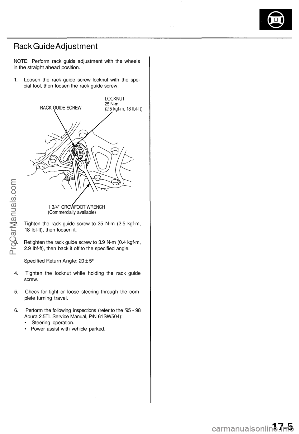
Rack Guide Adjustment
NOTE: Perform rack guide adjustment with the wheels
in the straight ahead position.
1. Loosen the rack guide screw locknut with the spe-
cial tool, then loosen the rack guide screw.
RACK GUIDE SCREW
LOCKNUT
25 N-m
(2.5 kgf-m, 18 Ibf-ft)
1 3/4" CROWFOOT WRENCH
(Commercially available)
2. Tighten the rack guide screw to 25 N-m (2.5 kgf-m,
18 Ibf-ft), then loosen it.
3. Retighten the rack guide screw to 3.9 N-m (0.4 kgf-m,
2.9 Ibf-ft), then back it off to the specified angle.
Specified Return Angle: 20 ± 5°
4. Tighten the locknut while holding the rack guide
screw.
5. Check for tight or loose steering through the com-
plete turning travel.
6. Perform the following inspections (refer to the '95 - 98
Acura 2.5TL Service Manual, P/N 61SW504):
• Steering operation.
• Power assist with vehicle parked.ProCarManuals.com
Page 514 of 1771
ABS Functio n Tes t
1. Rais e th e ca r of f th e ground , an d suppor t i t wit h safet y
stands .
2. Chec k tha t ther e is n o brak e drag .
3 . Tur n th e ignitio n switc h O N (II) , an d confir m tha t th e
AB S indicato r ligh t come s on .
• I f th e AB S indicato r ligh t doe s no t com e on , follo w
th e troubleshootin g o n pag e 19-16 .
4 . Hond a PG M Tester : Connec t th e PG M Teste r a s
describe d i n th e PG M Teste r Anti-Loc k Brak e
Syste m (ABS ) Vehicl e Syste m Supplement . Follo w
th e tester' s prompt s instea d o f step s 5 throug h 1 1
o f thi s procedure .
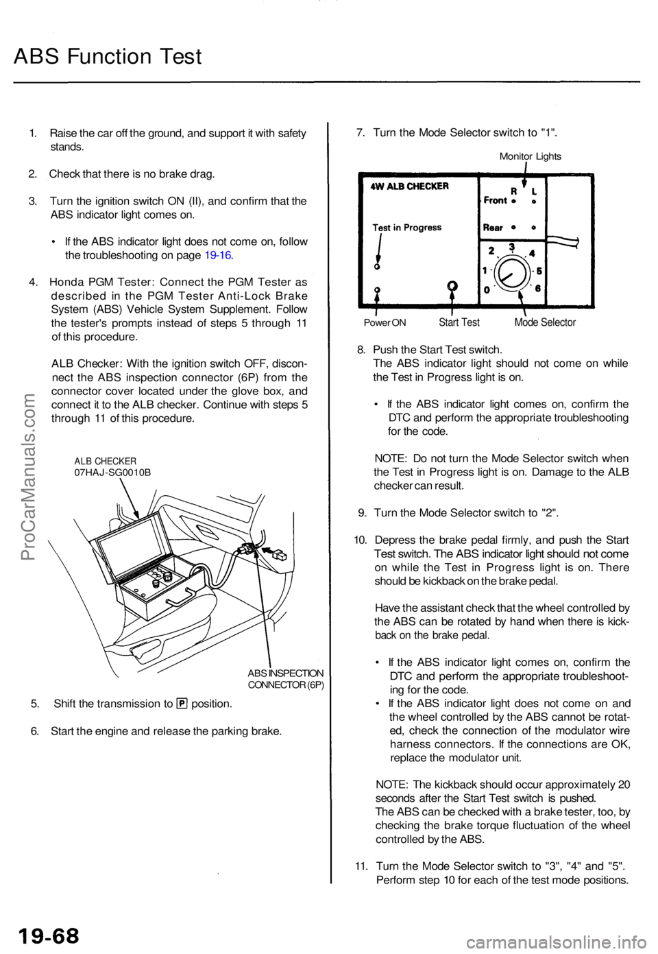
AL B Checker : Wit h th e ignitio n switc h OFF , discon -
nec t th e AB S inspectio n connecto r (6P ) fro m th e
connecto r cove r locate d unde r th e glov e box , an d
connec t i t t o th e AL B checker . Continu e wit h step s 5
throug h 1 1 o f thi s procedure .
ALB CHECKE R07HAJ-SG0010 B
ABS
INSPECTIO NCONNECTO R (6P )
5. Shif t th e transmissio n t o position .
6 . Star t th e engin e an d releas e th e parkin g brake . 7
. Tur n th e Mod e Selecto r switc h t o "1" .
Monito r Light s
Powe r O NStar t Tes t
8. Pus h th e Star t Tes t switch .
Th e AB S indicato r ligh t shoul d no t com e o n whil e
th e Tes t i n Progres s ligh t i s on .
• I f th e AB S indicato r ligh t come s on , confir m th e
DT C an d perfor m th e appropriat e troubleshootin g
fo r th e code .
NOTE : D o no t tur n th e Mod e Selecto r switc h whe n
th e Tes t i n Progres s ligh t i s on . Damag e to th e AL B
checke r ca n result .
9 . Tur n th e Mod e Selecto r switc h t o "2" .
10 . Depres s th e brak e peda l firmly , an d pus h th e Star t
Test switch . Th e AB S indicato r ligh t shoul d no t com e
on whil e th e Tes t i n Progres s ligh t i s on . Ther e
shoul d b e kickbac k o n th e brak e pedal .
Hav e th e assistan t chec k tha t th e whee l controlle d b y
th e AB S ca n b e rotate d b y han d whe n ther e is kick -
back o n th e brak e pedal .
• I f th e AB S indicato r ligh t come s on , confir m th e
DT C an d perfor m th e appropriat e troubleshoot -
ing fo r th e code .
• I f th e AB S indicato r ligh t doe s no t com e o n an d
th e whee l controlle d b y th e AB S canno t b e rotat -
ed , chec k th e connectio n o f th e modulato r wir e
harnes s connectors . I f th e connection s ar e OK ,
replac e th e modulato r unit .
NOTE : Th e kickbac k shoul d occu r approximatel y 2 0
second s afte r th e Star t Tes t switc h i s pushed .
Th e AB S can be checke d wit h a brak e tester , too , b y
checkin g th e brak e torqu e fluctuatio n o f th e whee l
controlle d b y th e ABS .
11 . Tur n th e Mod e Selecto r switc h t o "3" , "4 " an d "5" .
Perfor m ste p 1 0 fo r eac h o f th e tes t mod e positions .
Mode Selecto r
ProCarManuals.com
Page 1145 of 1771
System Descriptio n
This powe r steerin g syste m is speed-sensitive . It s mai n component s ar e a mechanica l spee d sensor , a rotar y valve-typ e
gearbox, an d a constan t volume , vane-typ e pump . Th e syste m regulate s th e powe r assis t accordin g to vehicl e speed , roa d
conditions , an d drivin g style . Th e amoun t o f powe r assis t change s linearl y fro m hig h assist , whe n drivin g a t lo w speed s o r
parking , t o lo w assist , whe n drivin g a t hig h speeds .
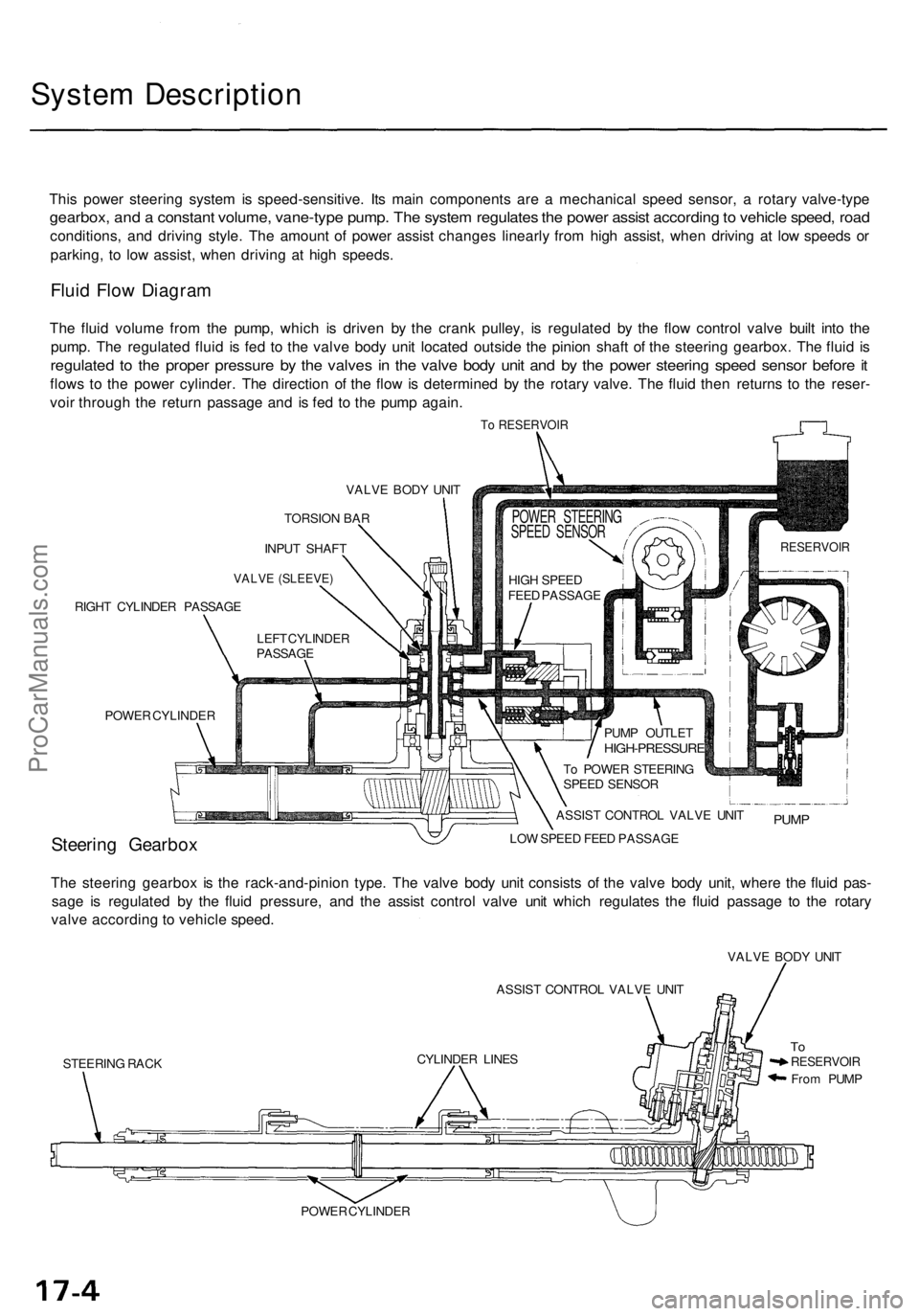
Fluid Flo w Diagra m
The flui d volum e fro m th e pump , whic h i s drive n b y th e cran k pulley , i s regulate d b y th e flo w contro l valv e buil t int o th e
pump . Th e regulate d flui d i s fe d t o th e valv e bod y uni t locate d outsid e th e pinio n shaf t o f th e steerin g gearbox . Th e flui d i s
regulate d t o th e prope r pressur e b y th e valve s i n th e valv e bod y uni t an d b y th e powe r steerin g spee d senso r befor e it
flow s t o th e powe r cylinder . Th e directio n o f th e flo w is determine d b y th e rotar y valve . Th e flui d the n returns to th e reser -
voi r throug h th e retur n passag e an d i s fe d t o th e pum p again .
To RESERVOI R
VALVE BOD Y UNI T
TORSIO N BA R
INPU T SHAF T
VALVE (SLEEVE )
RIGHT CYLINDE R PASSAG E
POWE R CYLINDE R
Steering Gearbo xLOW SPEE D FEE D PASSAG E
The steerin g gearbo x i s th e rack-and-pinio n type . Th e valv e bod y uni t consist s o f th e valv e bod y unit , wher e th e flui d pas -
sag e i s regulate d b y th e flui d pressure , an d th e assis t contro l valv e uni t whic h regulate s th e flui d passag e t o th e rotar y
valv e accordin g t o vehicl e speed .
ASSIST CONTRO L VALV E UNI T
STEERIN G RAC K VALV
E BOD Y UNI T
ToRESERVOI R
From PUM P
POWE R CYLINDE RCYLINDE
R LINE S ASSIS
T CONTRO L VALV E UNI T
PUM P
To POWE R STEERIN G
SPEE D SENSO R
PUM
P OUTLE T
HIGH-PRESSUR E
HIGH SPEE D
FEE D PASSAG E
POWER STEERIN G
SPEE D SENSO R
RESERVOI R
LEFT CYLINDE R
PASSAG E
ProCarManuals.com
Page 1152 of 1771
System Description
System Operation (cont'd)
Hydraulic Control at Each Speed Range
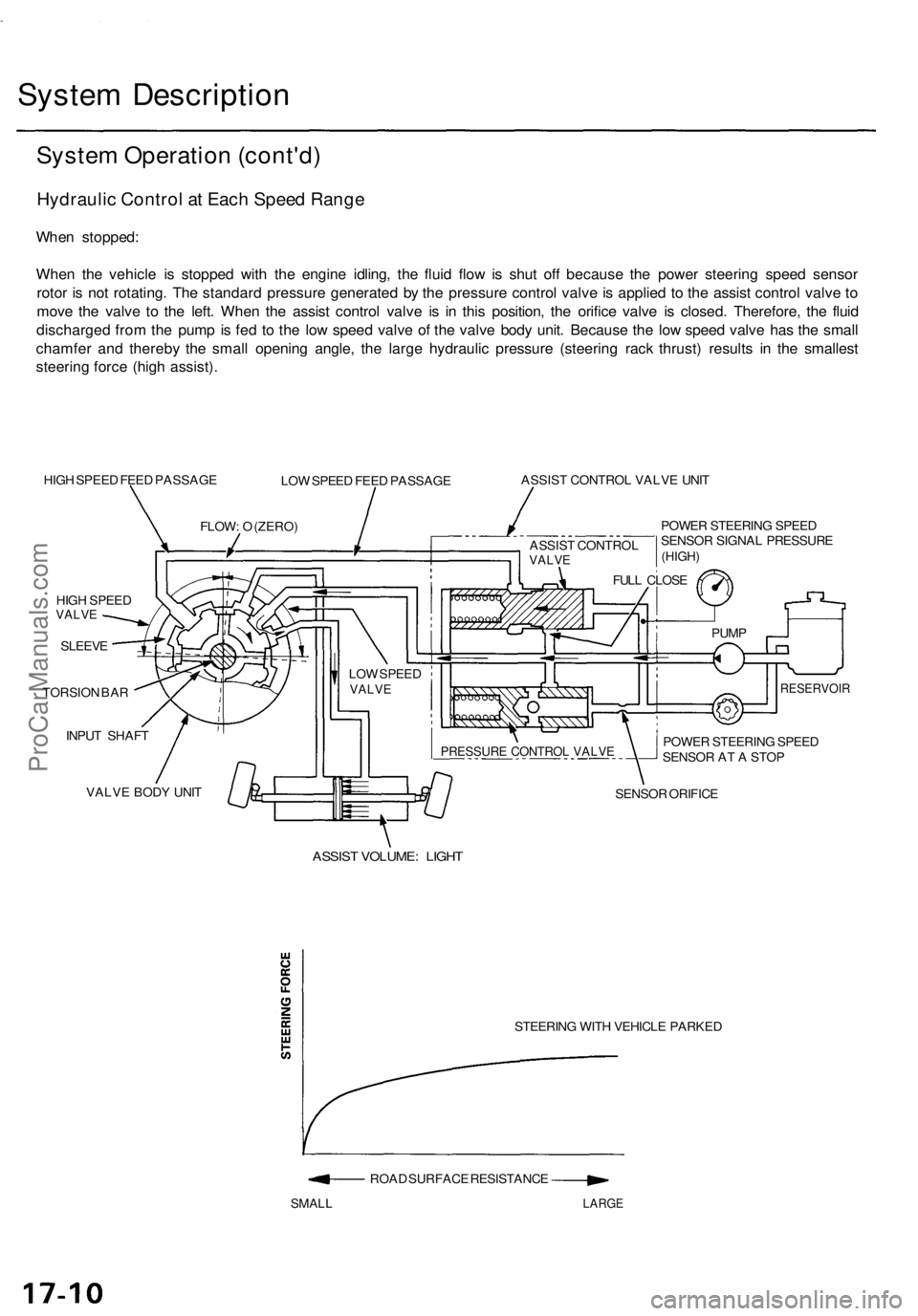
When stopped:
When the vehicle is stopped with the engine idling, the fluid flow is shut off because the power steering speed sensor
rotor is not rotating. The standard pressure generated by the pressure control valve is applied to the assist control valve to
move the valve to the left. When the assist control valve is in this position, the orifice valve is closed. Therefore, the fluid
discharged from the pump is fed to the low speed valve of the valve body unit. Because the low speed valve has the small
chamfer and thereby the small opening angle, the large hydraulic pressure (steering rack thrust) results in the smallest
steering force (high assist).
HIGH SPEED FEED PASSAGE
LOW SPEED FEED PASSAGE
ASSIST CONTROL VALVE UNIT
POWER STEERING SPEED
SENSOR SIGNAL PRESSURE
HIGH SPEED
VALVE
SLEEVE
TORSION BAR
INPUT SHAFT
VALVE BODY UNIT
SENSOR ORIFICE
ASSIST VOLUME: LIGHT
STEERING WITH VEHICLE PARKED
ROAD SURFACE RESISTANCE
SMALL
LARGE
FLOW: O (ZERO)
LOW SPEED
VALVE
POWER STEERING SPEED
SENSOR AT A STOP
RESERVOIR
PUMP
FULL CLOSE
PRESSURE CONTROL VALVE
(HIGH)
ASSIST CONTROL
VALVEProCarManuals.com
Page 1156 of 1771
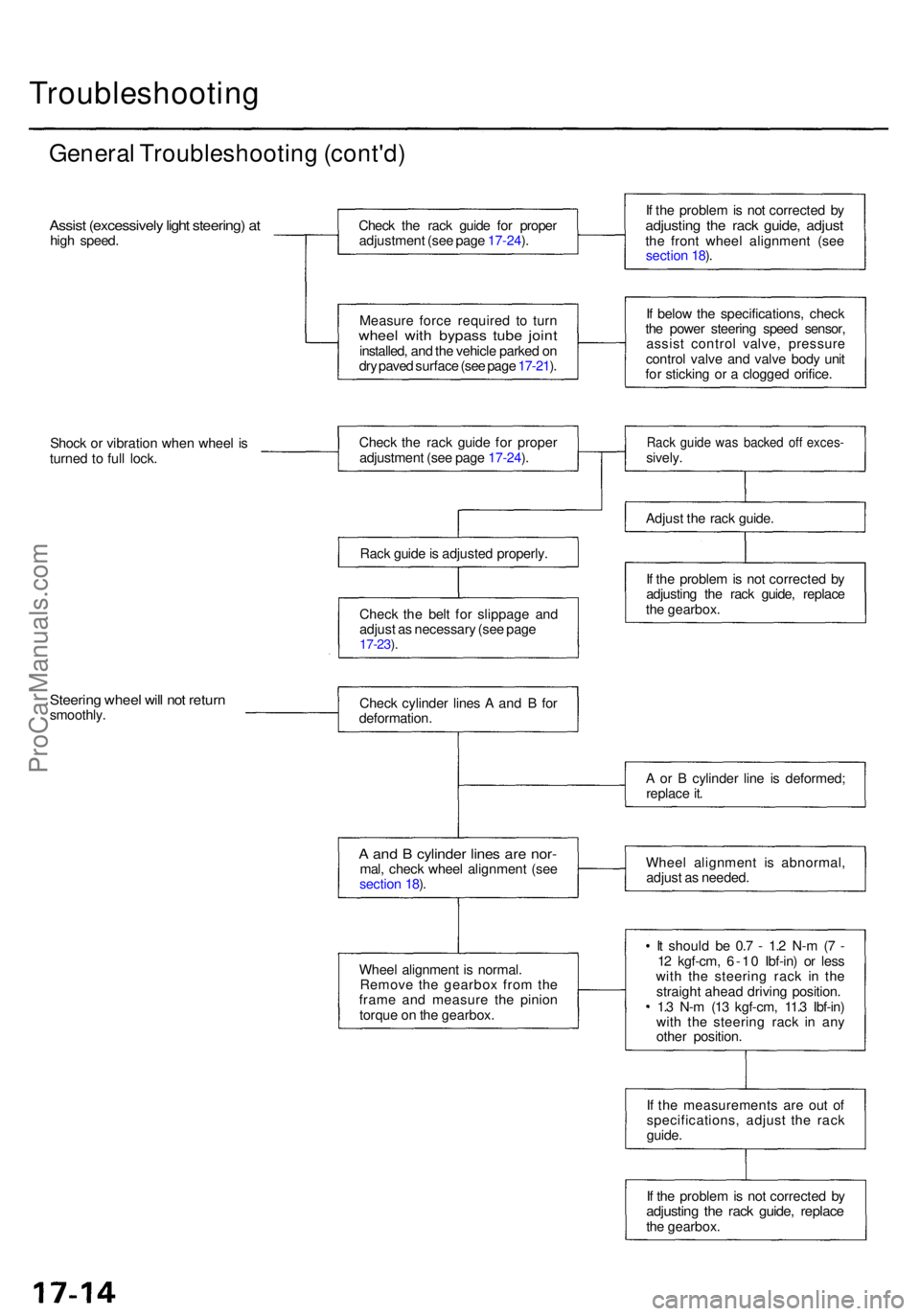
Troubleshooting
General Troubleshootin g (cont'd )
Assist (excessivel y ligh t steering ) a thig h speed . Chec
k th e rac k guid e fo r prope r
adjustmen t (se e pag e 17-24 ).
Measur e forc e require d t o tur n
whee l wit h bypas s tub e join tinstalled , an d th e vehicl e parke d o n
dr y pave d surfac e (se e pag e 17-21 ). I
f th e proble m is no t correcte d b y
adjustin g th e rac k guide , adjus tthe fron t whee l alignmen t (se e
sectio n 18 ).
I f belo w th e specifications , chec k
th e powe r steerin g spee d sensor ,
assis t contro l valve , pressur e
contro l valv e an d valv e bod y uni t
fo r stickin g o r a clogge d orifice .
Shoc k o r vibratio n whe n whee l i s
turne d t o ful l lock . Chec
k th e rac k guid e fo r prope r
adjustmen t (se e pag e 17-24 ).
Rac k guid e is adjuste d properly .
Chec k th e bel t fo r slippag e an d
adjus t a s necessar y (se e pag e
17-23 ).
Rac k guid e wa s backe d of f exces -sively.
Adjus t th e rac k guide .
I f th e proble m is no t correcte d b y
adjustin g th e rac k guide , replac e
th e gearbox .
Steering whee l wil l no t retur nsmoothly . Chec
k cylinde r line s A an d B fo r
deformation .
A an d B cylinde r line s ar e nor -mal, chec k whee l alignmen t (se e
sectio n 18 ).
Whee l alignmen t i s normal .
Remov e th e gearbo x fro m th e
fram e an d measur e th e pinio n
torqu e o n th e gearbox . A
o r B cylinde r lin e i s deformed ;
replac e it .
Whee l alignmen t i s abnormal ,
adjus t a s needed .
I t shoul d b e 0. 7 - 1. 2 N- m (7 -
1 2 kgf-cm , 6-1 0 Ibf-in ) o r les s
wit h th e steerin g rac k i n th e
straigh t ahea d drivin g position .
1. 3 N- m (1 3 kgf-cm , 11. 3 Ibf-in )
wit h th e steerin g rac k i n an y
othe r position .
I f th e measurement s ar e ou t o f
specifications , adjus t th e rac k
guide .
I f th e proble m is no t correcte d b y
adjustin g th e rac k guide , replac ethe gearbox .
ProCarManuals.com
Page 1305 of 1771
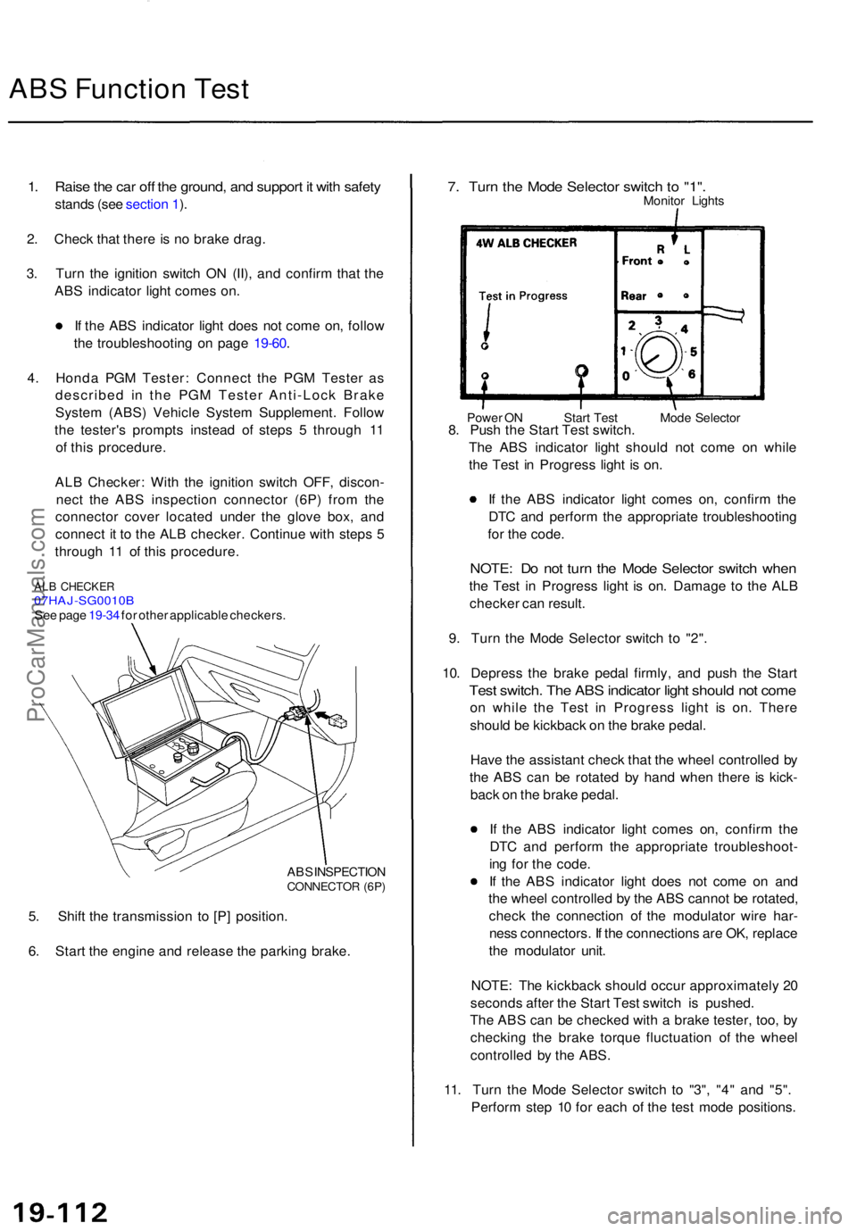
ABS Functio n Tes t
1. Rais e th e ca r of f th e ground , an d suppor t i t wit h safet y
stand s (se e sectio n 1 ).
2 . Chec k tha t ther e is n o brak e drag .
3 . Tur n th e ignitio n switc h O N (II) , an d confir m tha t th e
AB S indicato r ligh t come s on .
I f th e AB S indicato r ligh t doe s no t com e on , follo w
th e troubleshootin g o n pag e 19-60 .
4 . Hond a PG M Tester : Connec t th e PG M Teste r a s
describe d i n th e PG M Teste r Anti-Loc k Brak e
Syste m (ABS ) Vehicl e Syste m Supplement . Follo w
th e tester' s prompt s instea d o f step s 5 throug h 1 1
o f thi s procedure .
AL B Checker : Wit h th e ignitio n switc h OFF , discon -
nec t th e AB S inspectio n connecto r (6P ) fro m th e
connecto r cove r locate d unde r th e glov e box , an d
connec t i t t o th e AL B checker . Continu e wit h step s 5
throug h 1 1 o f thi s procedure .
ALB CHECKE R07HAJ-SG0010 BSee pag e 19-34 for othe r applicabl e checkers .
AB S INSPECTIO N
CONNECTO R (6P )
5. Shif t th e transmissio n t o [P ] position .
6 . Star t th e engin e an d releas e th e parkin g brake .
7. Tur n th e Mod e Selecto r switc h t o "1" .Monito r Light s
Power O N Star t Tes t Mod e Selecto r8. Pus h th e Star t Tes t switch .
Th e AB S indicato r ligh t shoul d no t com e o n whil e
th e Tes t i n Progres s ligh t i s on .
I f th e AB S indicato r ligh t come s on , confir m th e
DT C an d perfor m th e appropriat e troubleshootin g
fo r th e code .
NOTE : D o no t tur n th e Mod e Selecto r switc h whe n
the Tes t i n Progres s ligh t i s on . Damag e t o th e AL B
checke r ca n result .
9 . Tur n th e Mod e Selecto r switc h t o "2" .
10 . Depres s th e brak e peda l firmly , an d pus h th e Star t
Test switch . Th e AB S indicato r ligh t shoul d no t com e
on whil e th e Tes t i n Progres s ligh t i s on . Ther e
shoul d b e kickbac k o n th e brak e pedal .
Hav e th e assistan t chec k tha t th e whee l controlle d b y
th e AB S ca n b e rotate d b y han d whe n ther e i s kick -
bac k o n th e brak e pedal .
I f th e AB S indicato r ligh t come s on , confir m th e
DT C an d perfor m th e appropriat e troubleshoot -
in g fo r th e code .
I f th e AB S indicato r ligh t doe s no t com e o n an d
th e whee l controlle d b y th e AB S canno t b e rotated ,
chec k th e connectio n o f th e modulato r wir e har -
nes s connectors . I f th e connection s ar e OK , replac e
th e modulato r unit .
NOTE : Th e kickbac k shoul d occu r approximatel y 2 0
second s afte r th e Star t Tes t switc h is pushed .
Th e AB S ca n b e checke d wit h a brak e tester , too , b y
checkin g th e brak e torqu e fluctuatio n o f th e whee l
controlle d b y th e ABS .
11 . Tur n th e Mod e Selecto r switc h t o "3" , "4 " an d "5" .
Perfor m ste p 1 0 fo r eac h o f th e tes t mod e positions .
ProCarManuals.com