1995 ACURA TL torque
[x] Cancel search: torquePage 298 of 1771
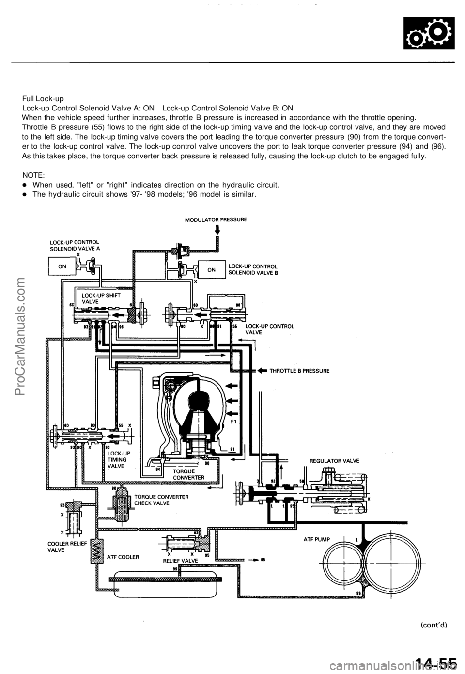
Full Lock-up
Lock-up Control Solenoid Valve A: ON Lock-up Control Solenoid Valve B: ON
When the vehicle speed further increases, throttle B pressure is increased in accordance with the throttle opening.
Throttle B pressure (55) flows to the right side of the lock-up timing valve and the lock-up control valve, and they are moved
to the left side. The lock-up timing valve covers the port leading the torque converter pressure (90) from the torque convert-
er to the lock-up control valve. The lock-up control valve uncovers the port to leak torque converter pressure (94) and (96).
As this takes place, the torque converter back pressure is released fully, causing the lock-up clutch to be engaged fully.
NOTE:
When used, "left" or "right" indicates direction on the hydraulic circuit.
The hydraulic circuit shows '97- '98 models; '96 model is similar.ProCarManuals.com
Page 299 of 1771
Description
Lock-up System (cont'd)
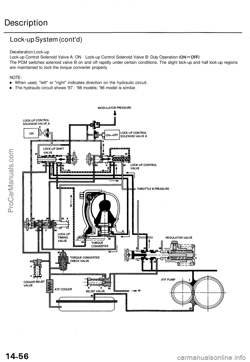
Deceleration Lock-up
Lock-up Control Solenoid Valve A: ON Lock-up Control Solenoid Valve B: Duty Operation
The PCM switches solenoid valve B on and off rapidly under certain conditions. The slight lock-up and half lock-up regions
are maintained to lock the torque converter properly.
NOTE:
When used, "left" or "right" indicates direction on the hydraulic circuit.
The hydraulic circuit shows '97 - '98 models; '96 model is similar.ProCarManuals.com
Page 316 of 1771
Mainshaft/Countershaft Speed Sensors
Replacement (cont'd)
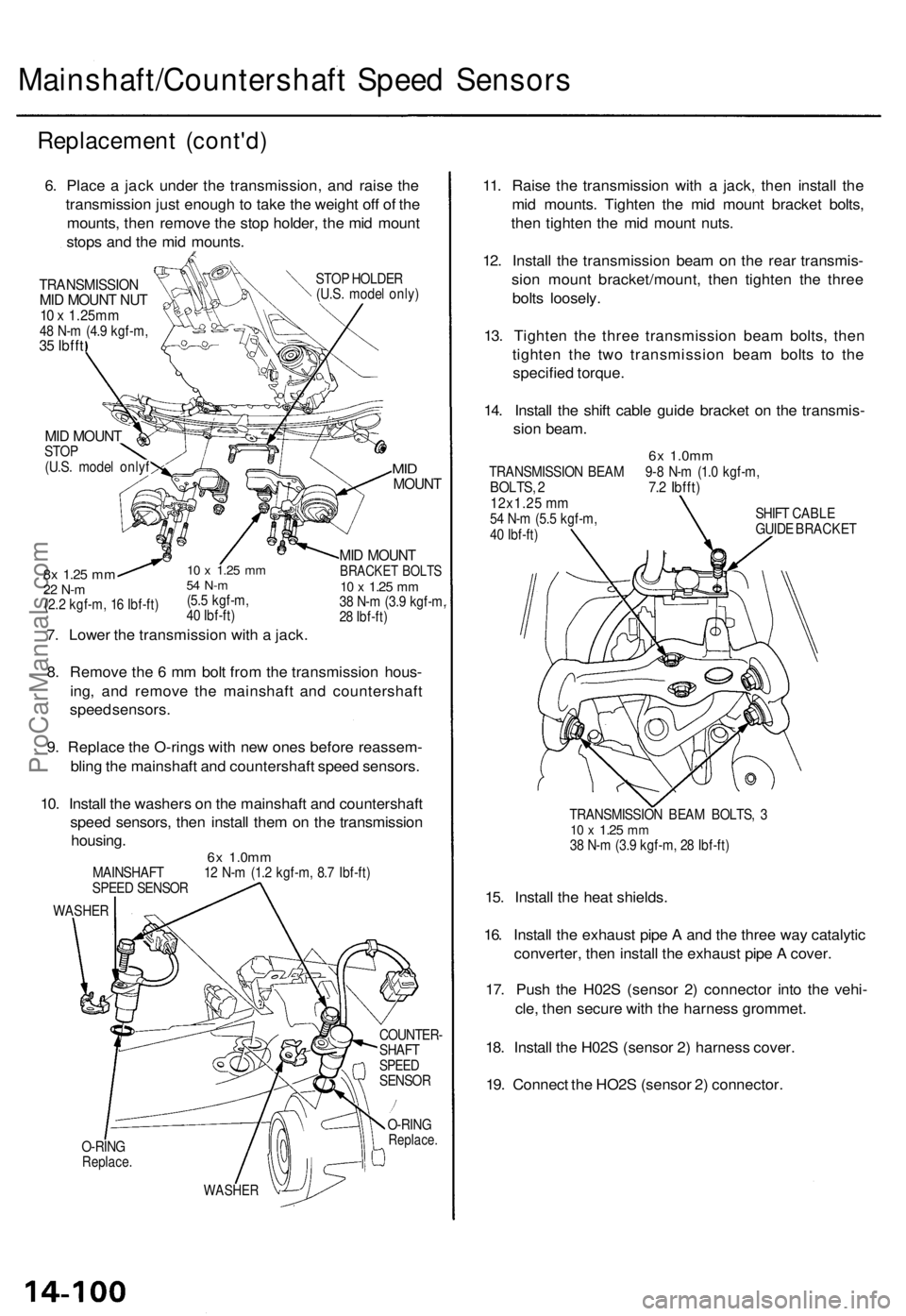
6. Place a jack under the transmission, and raise the
transmission just enough to take the weight off of the
mounts, then remove the stop holder, the mid mount
stops and the mid mounts.
TRANSMISSION
MID MOUNT NUT
10 x 1.25mm
48 N-m (4.9 kgf-m,
35 Ibfft
STOP HOLDER
(U.S. model only)
MID MOUNT
STOP
(U.S. model onlyf
10 x
1.25
mm
54 N-m
(5.5 kgf-m,
40 Ibf-ft)
7. Lower the transmission with a jack.
8x
1.25
mm
22 N-m
(2.2 kgf-m, 16 Ibf-ft)
MID
MOUNT
MID MOUNT
BRACKET BOLTS
10 x
1.25
mm
38 N-m (3.9 kgf-m,
28 Ibf-ft)
8. Remove the 6 mm bolt from the transmission hous-
ing, and remove the mainshaft and countershaft
speed sensors.
9. Replace the O-rings with new ones before reassem-
bling the mainshaft and countershaft speed sensors.
10. Install the washers on the mainshaft and countershaft
speed sensors, then install them on the transmission
housing.
6x
1.0mm
MAINSHAFT 12 N-m (1.2 kgf-m, 8.7 Ibf-ft)
SPEED SENSOR
WASHER
O-RING
Replace.
COUNTER-
SHAFT
SPEED
SENSOR
O-RING
Replace.
WASHER
11. Raise the transmission with a jack, then install the
mid mounts. Tighten the mid mount bracket bolts,
then tighten the mid mount nuts.
12. Install the transmission beam on the rear transmis-
sion mount bracket/mount, then tighten the three
bolts loosely.
13. Tighten the three transmission beam bolts, then
tighten the two transmission beam bolts to the
specified torque.
14. Install the shift cable guide bracket on the transmis-
sion beam.
6x
1.0mm
TRANSMISSION BEAM 9-8 N-m (1.0 kgf-m,
BOLTS, 2 7.2 Ibfft)
12x1.25 mm
54 N-m (5.5 kgf-m,
40 Ibf-ft)
SHIFT CABLE
GUIDE BRACKET
TRANSMISSION BEAM BOLTS, 3
10 x
1.25
mm
38 N-m (3.9 kgf-m, 28 Ibf-ft)
15. Install the heat shields.
16. Install the exhaust pipe A and the three way catalytic
converter, then install the exhaust pipe A cover.
17. Push the H02S (sensor 2) connector into the vehi-
cle, then secure with the harness grommet.
18. Install the H02S (sensor 2) harness cover.
19. Connect the HO2S (sensor 2) connector.ProCarManuals.com
Page 318 of 1771
A/T Gea r Positio n Switc h
Replacemen t (cont'd )
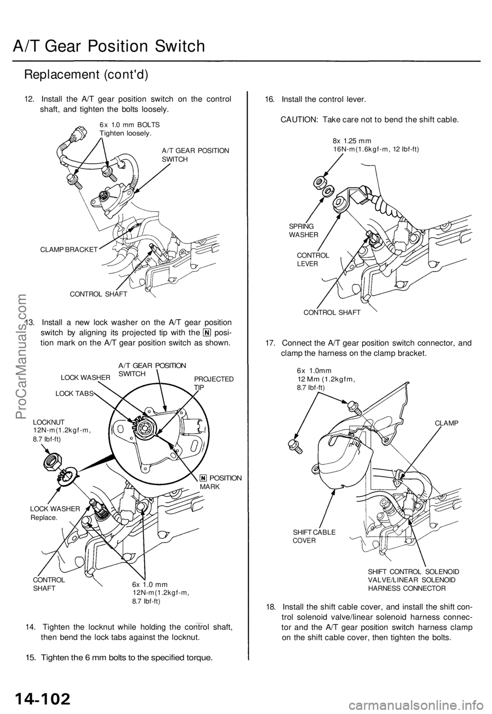
12. Instal l th e A/ T gea r positio n switc h o n th e contro l
shaft , an d tighte n th e bolt s loosely .
6x 1. 0 m m BOLT STighten loosely .
A/T GEA R POSITIO N
SWITC H
CLAM P BRACKE T
CONTRO L SHAF T
13. Instal l a ne w loc k washe r o n th e A/ T gea r positio n
switch b y alignin g it s projecte d ti p wit h th e posi -
tio n mar k o n th e A/ T gea r positio n switc h a s shown .
LOCK WASHE R
LOC K TAB S
LOCKNU T
12N-m(1.2kgf-m ,
8. 7 Ibf-ft )
A/T GEA R POSITIO NSWITCHPROJECTE DTIP
LOC K WASHE RReplace.
CONTRO L
SHAF T6x 1. 0 m m12N-m(1.2kgf-m ,
8. 7 Ibf-ft )
14. Tighte n th e locknu t whil e holdin g th e contro l shaft ,
the n ben d th e loc k tab s agains t th e locknut .
15. Tighte n th e 6 m m bolt s to th e specifie d torque .
16. Instal l th e contro l lever .
CAUTION : Tak e car e no t t o ben d th e shif t cable .
8x 1.2 5 mm16N-m(1.6kgf-m , 1 2 Ibf-ft )
SPRIN G
WASHE R
CONTRO LLEVER
CONTRO L SHAF T
17. Connec t th e A/ T gea r positio n switc h connector , an d
clam p th e harnes s o n th e clam p bracket .
6x 1.0m m12 M m (1.2kgfm ,8.7 Ibf-ft )
CLAMP
SHIF T CABL E
COVER
SHIFT CONTRO L SOLENOI D
VALVE/LINEA R SOLENOI D
HARNES S CONNECTO R
18. Instal l th e shif t cabl e cover , an d instal l th e shif t con -
tro l solenoi d valve/linea r solenoi d harnes s connec -
to r an d th e A/ T gea r positio n switc h harnes s clam p
o n th e shif t cabl e cover , the n tighte n th e bolts .
MARKPOSITIO N
ProCarManuals.com
Page 321 of 1771
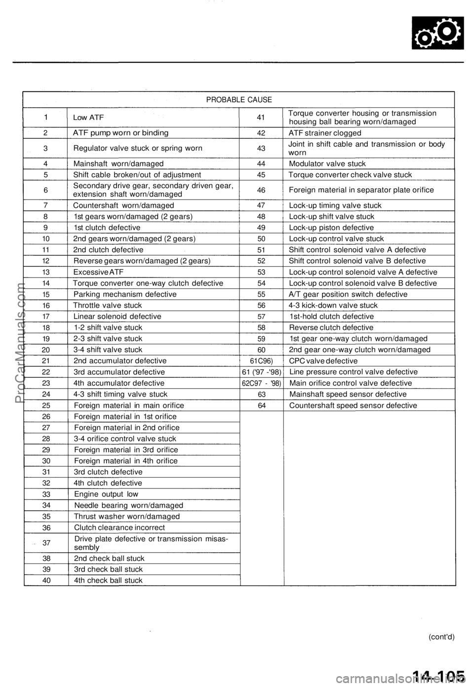
PROBABLE CAUSE
1
2
3
4
5
6
7
8
9
10
11
12
13
14
15
16
17
18
19
20
21
22
23
24
25
26
27
28
29
30
31
32
33
34
35
36
37
38
39
40
Low ATF
ATF pump worn or binding
Regulator valve stuck or spring worn
Mainshaft worn/damaged
Shift cable broken/out of adjustment
Secondary drive gear, secondary driven gear,
extension shaft worn/damaged
Countershaft worn/damaged
1st gears worn/damaged (2 gears)
1st clutch defective
2nd gears worn/damaged (2 gears)
2nd clutch defective
Reverse gears worn/damaged (2 gears)
Excessive ATF
Torque converter one-way clutch defective
Parking mechanism defective
Throttle valve stuck
Linear solenoid defective
1-2 shift valve stuck
2-3 shift valve stuck
3-4 shift valve stuck
2nd accumulator defective
3rd accumulator defective
4th accumulator defective
4-3 shift timing valve stuck
Foreign material in main orifice
Foreign material in 1st orifice
Foreign material in 2nd orifice
3-4 orifice control valve stuck
Foreign material in 3rd orifice
Foreign material in 4th orifice
3rd clutch defective
4th clutch defective
Engine output low
Needle bearing worn/damaged
Thrust washer worn/damaged
Clutch clearance incorrect
Drive plate defective or transmission misas-
sembly
2nd check ball stuck
3rd check ball stuck
4th check ball stuck
41
42
43
44
45
46
47
48
49
50
51
52
53
54
55
56
57
58
59
60
61C96)
61
('97 -'98)
62C97 - '98)
63
64
Torque converter housing or transmission
housing ball bearing worn/damaged
ATF strainer clogged
Joint in shift cable and transmission or body
worn
Modulator valve stuck
Torque converter check valve stuck
Foreign material in separator plate orifice
Lock-up timing valve stuck
Lock-up shift valve stuck
Lock-up piston defective
Lock-up control valve stuck
Shift control solenoid valve A defective
Shift control solenoid valve B defective
Lock-up control solenoid valve A defective
Lock-up control solenoid valve B defective
A/T gear position switch defective
4-3 kick-down valve stuck
1st-hold clutch defective
Reverse clutch defective
1st gear one-way clutch worn/damaged
2nd gear one-way clutch worn/damaged
CPC valve defective
Line pressure control valve defective
Main orifice control valve defective
Mainshaft speed sensor defective
Countershaft speed sensor defective
(cont'd)ProCarManuals.com
Page 322 of 1771
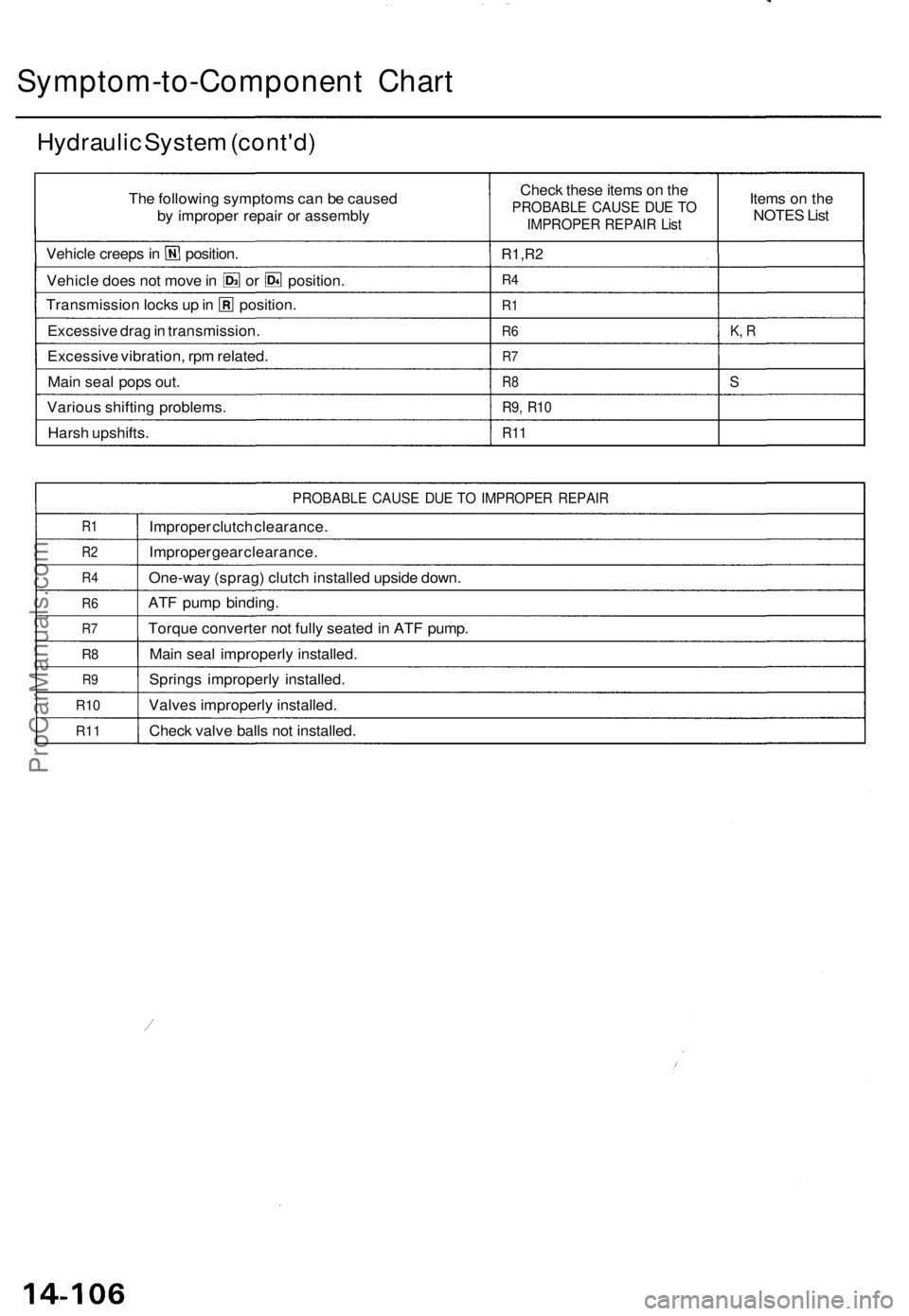
Symptom-to-Component Chart
Hydraulic System (cont'd)
The following symptoms can be caused
by improper repair or assembly
Vehicle creeps in position.
Vehicle does not move in or position.
Transmission locks up in position.
Excessive drag in transmission.
Excessive vibration, rpm related.
Main seal pops out.
Various shifting problems.
Harsh upshifts.
Check these items on the
PROBABLE CAUSE DUE TO
IMPROPER REPAIR List
R1,R2
R4
R1
R6
R7
R8
R9, R10
R11
Items on the
NOTES List
K, R
S
PROBABLE CAUSE DUE TO IMPROPER REPAIR
R1
R2
R4
R6
R7
R8
R9
R10
R11
Improper clutch clearance.
Improper gear clearance.
One-way (sprag) clutch installed upside down.
ATF pump binding.
Torque converter not fully seated in ATF pump.
Main seal improperly installed.
Springs improperly installed.
Valves improperly installed.
Check valve balls not installed.ProCarManuals.com
Page 329 of 1771
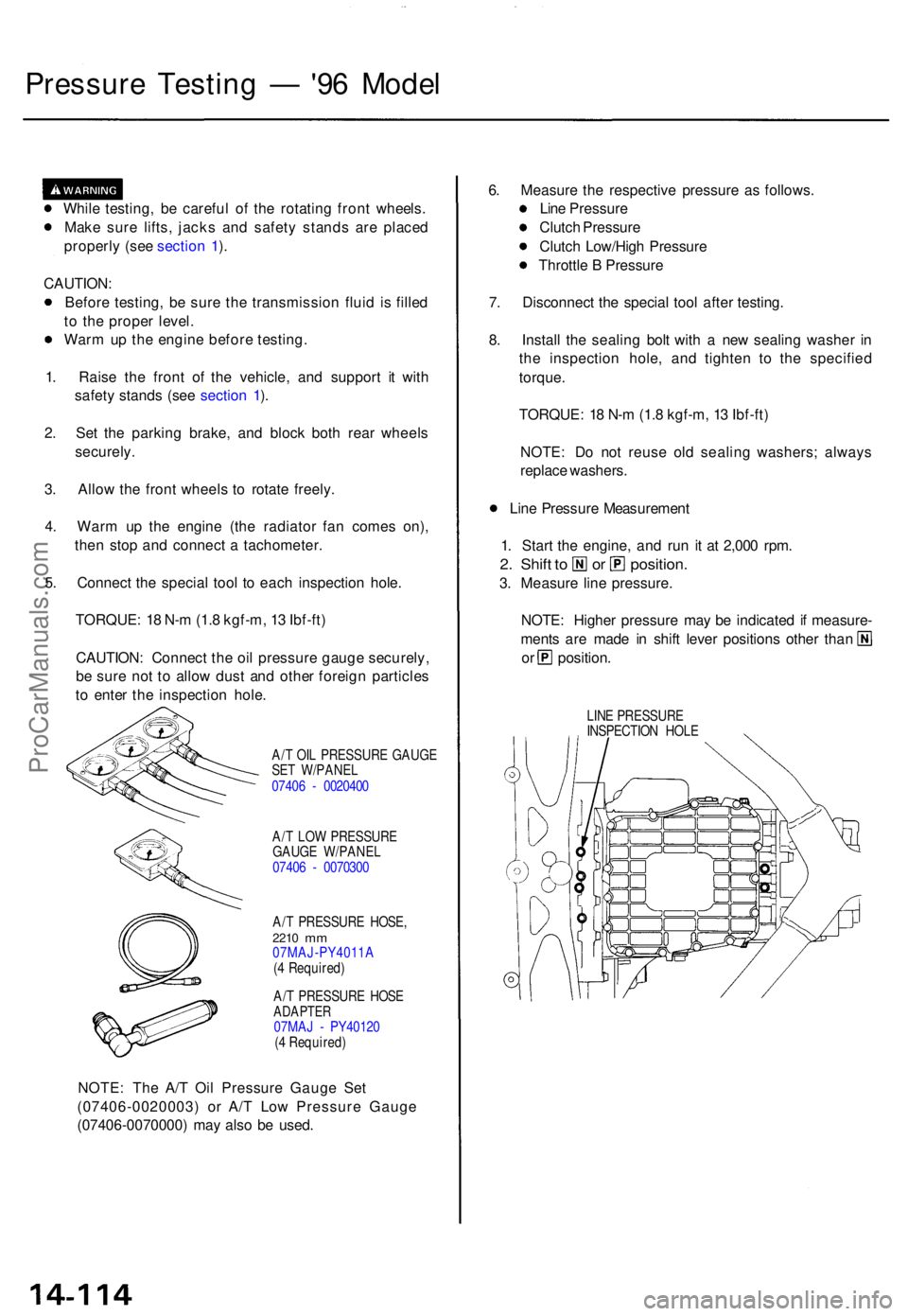
Pressure Testin g — '96 Mode l
While testing , b e carefu l o f th e rotatin g fron t wheels .
Mak e sur e lifts , jack s an d safet y stand s ar e place d
properl y (se e sectio n 1 ).
CAUTION :
Befor e testing , b e sur e th e transmissio n flui d i s fille d
t o th e prope r level .
War m u p th e engin e befor e testing .
1 . Rais e th e fron t o f th e vehicle , an d suppor t i t wit h
safet y stand s (se e sectio n 1 ).
2 . Se t th e parkin g brake , an d bloc k bot h rea r wheel s
securely .
3 . Allo w th e fron t wheel s t o rotat e freely .
4 . War m u p th e engin e (th e radiato r fa n come s on) ,
the n sto p an d connec t a tachometer .
5 . Connec t th e specia l too l t o eac h inspectio n hole .
TORQUE : 1 8 N- m (1. 8 kgf-m , 1 3 Ibf-ft )
CAUTION : Connec t th e oi l pressur e gaug e securely ,
b e sur e no t t o allo w dus t an d othe r foreig n particle s
t o ente r th e inspectio n hole .
A/T OI L PRESSUR E GAUG E
SE T W/PANE L
0740 6 - 002040 0
A/ T LO W PRESSUR E
GAUG E W/PANE L
0740 6 - 007030 0
A/ T PRESSUR E HOSE ,
2210 mm07MAJ-PY4011 A
( 4 Required )
A/ T PRESSUR E HOS E
ADAPTE R07MAJ - PY4012 0
( 4 Required )
NOTE: Th e A/ T Oi l Pressur e Gaug e Se t
(07406-0020003 ) o r A/ T Lo w Pressur e Gaug e
(07406-0070000 ) ma y als o b e used . 6
. Measur e th e respectiv e pressur e a s follows .
Lin e Pressur e
Clutc h Pressur e
Clutc h Low/Hig h Pressur e
Throttl e B Pressur e
7 . Disconnec t th e specia l too l afte r testing .
8 . Instal l th e sealin g bol t wit h a ne w sealin g washe r i n
th e inspectio n hole , an d tighte n t o th e specifie d
torque .
TORQUE : 1 8 N- m (1. 8 kgf-m , 1 3 Ibf-ft )
NOTE : D o no t reus e ol d sealin g washers ; alway s
replac e washers .
Lin e Pressur e Measuremen t
1 . Star t th e engine , an d ru n i t a t 2,00 0 rpm .
2. Shif t t o o r position .
3. Measur e lin e pressure .
NOTE : Highe r pressur e ma y b e indicate d if measure -
ments ar e mad e i n shif t leve r position s othe r tha n
or position .
LINE PRESSUR E
INSPECTIO N HOL E
ProCarManuals.com
Page 333 of 1771
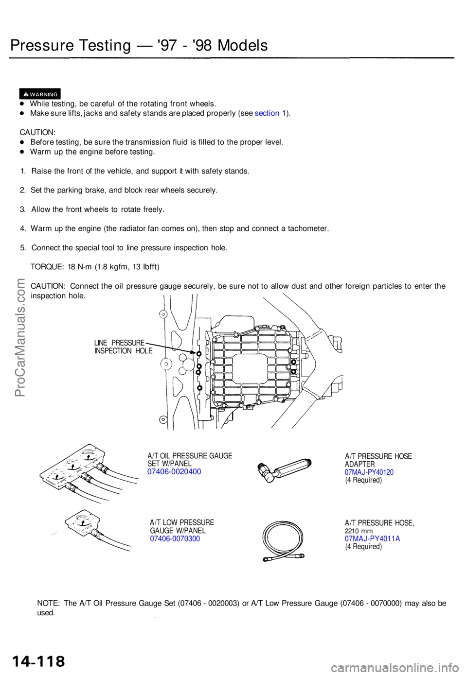
Pressure Testin g — '97 - '9 8 Model s
While testing , b e carefu l o f th e rotatin g fron t wheels .
Mak e sur e lifts , jack s an d safet y stand s ar e place d properl y (se e sectio n 1 ).
CAUTION :
Befor e testing , b e sur e th e transmissio n flui d is fille d to th e prope r level .
War m u p th e engin e befor e testing .
1 . Rais e th e fron t o f th e vehicle , an d suppor t i t wit h safet y stands .
2 . Se t th e parkin g brake , an d bloc k rea r wheel s securely .
3 . Allo w th e fron t wheel s t o rotat e freely .
4 . War m u p th e engin e (th e radiato r fa n come s on) , the n sto p an d connec t a tachometer .
5 . Connec t th e specia l too l t o lin e pressur e inspectio n hole .
TORQUE : 1 8 N- m (1. 8 kgfm , 1 3 Ibfft )
CAUTION : Connec t th e oi l pressur e gaug e securely , b e sur e no t t o allo w dus t an d othe r foreig n particle s t o ente r th e
inspectio n hole .
LINE PRESSUR E
INSPECTIO N HOL E
A/ T OI L PRESSUR E GAUG E
SE T W/PANE L
07406-0020400
A/T LO W PRESSUR E
GAUG E W/PANE L
07406-007030 0
A/T PRESSUR E HOS EADAPTE R07MAJ-PY4012 0
( 4 Required )
A/ T PRESSUR E HOSE ,
2210 mm07MAJ-PY4011 A(4 Required )
NOTE: Th e A/ T Oi l Pressur e Gaug e Se t (0740 6 - 0020003 ) o r A/ T Lo w Pressur e Gaug e (0740 6 - 0070000 ) ma y als o b e
used .
ProCarManuals.com