1995 ACURA TL torque
[x] Cancel search: torquePage 418 of 1771
1. Instal l th e torqu e converte r housin g separato r plat e
an d thre e dowe l pin s o n th e torqu e converte r hous -
ing.
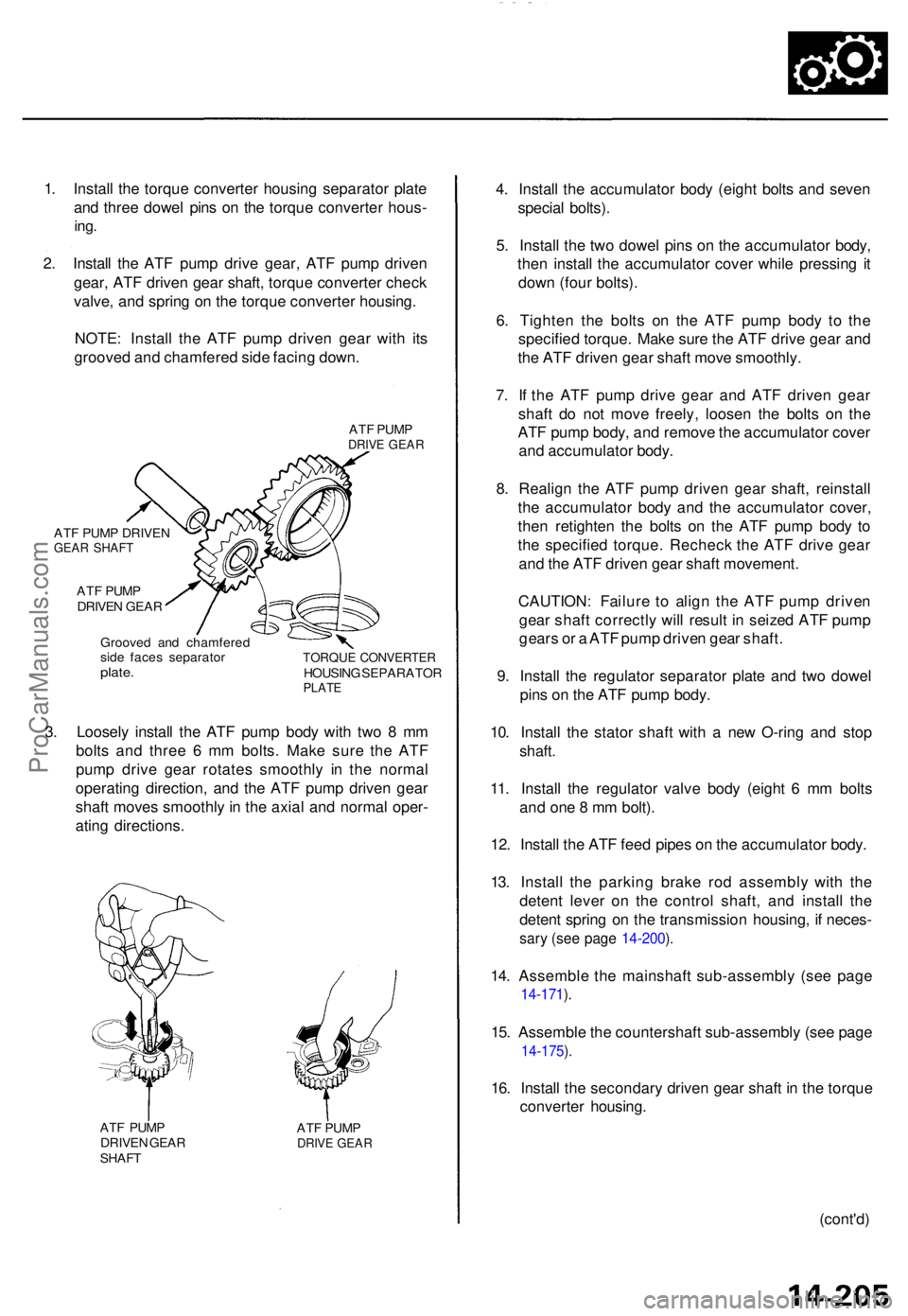
2. Instal l th e AT F pum p driv e gear , AT F pum p drive n
gear , AT F drive n gea r shaft , torqu e converte r chec k
valve , an d sprin g o n th e torqu e converte r housing .
NOTE : Instal l th e AT F pum p drive n gea r wit h it s
groove d an d chamfere d sid e facin g down .
ATF PUM PDRIV E GEA R
ATF PUM P DRIVE NGEAR SHAF T
ATF PUM P
DRIVE N GEA R
Groove d an d chamfere d
sid e face s separato r
plate.TORQU E CONVERTE RHOUSING SEPARATO RPLATE
3. Loosel y instal l th e AT F pum p bod y wit h tw o 8 m m
bolt s an d thre e 6 m m bolts . Mak e sur e th e AT F
pum p driv e gea r rotate s smoothl y i n th e norma l
operating direction, an d th e AT F pum p drive n gea r
shaf t move s smoothl y in th e axia l an d norma l oper -
atin g directions .
ATF PUM P
DRIVE N GEA R
SHAF T AT
F PUM PDRIVE GEAR
4. Instal l th e accumulato r bod y (eigh t bolt s an d seve n
specia l bolts) .
5 . Instal l th e tw o dowe l pin s o n th e accumulato r body ,
the n instal l th e accumulato r cove r whil e pressin g i t
dow n (fou r bolts) .
6 . Tighte n th e bolt s o n th e AT F pum p bod y t o th e
specifie d torque . Mak e sur e th e AT F driv e gea r an d
th e AT F drive n gea r shaf t mov e smoothly .
7 . I f th e AT F pum p driv e gea r an d AT F drive n gea r
shaf t d o no t mov e freely , loose n th e bolt s o n th e
AT F pum p body , an d remov e th e accumulato r cove r
an d accumulato r body .
8 . Realig n th e AT F pum p drive n gea r shaft , reinstal l
th e accumulato r bod y an d th e accumulato r cover ,
the n retighte n th e bolt s o n th e AT F pum p bod y t o
th e specifie d torque . Rechec k th e AT F driv e gea r
an d th e AT F drive n gea r shaf t movement .
CAUTION : Failur e t o alig n th e AT F pum p drive n
gea r shaf t correctl y wil l resul t i n seize d AT F pum p
gear s o r a AT F pum p drive n gea r shaft .
9 . Instal l th e regulato r separato r plat e an d tw o dowe l
pin s o n th e AT F pum p body .
10 . Instal l th e stato r shaf t wit h a ne w O-rin g an d sto p
shaft .
11. Instal l th e regulato r valv e bod y (eigh t 6 m m bolt s
an d on e 8 m m bolt) .
12 . Instal l th e AT F fee d pipe s o n th e accumulato r body .
13 . Instal l th e parkin g brak e ro d assembl y wit h th e
deten t leve r o n th e contro l shaft , an d instal l th e
deten t sprin g o n th e transmissio n housing , i f neces -
sary (se e pag e 14-200 ).
14 . Assembl e th e mainshaf t sub-assembl y (se e pag e
14-171 ).
15 . Assembl e th e countershaf t sub-assembl y (se e pag e
14-175 ).
16 . Instal l th e secondar y drive n gea r shaf t i n th e torqu e
converte r housing .
(cont'd)
ProCarManuals.com
Page 419 of 1771
Transmission
Reassembly (cont'd)
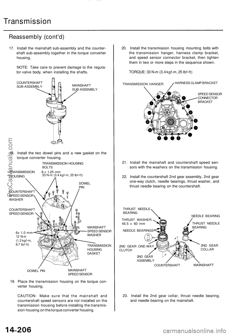
17. Install the mainshaft sub-assembly and the counter-
shaft sub-assembly together in the torque converter
housing.
NOTE: Take care to prevent damage to the regula-
tor valve body, when installing the shafts.
COUNTERSHAFT
SUB-ASSEMBLY
MAINSHAFT
SUB-ASSEMBLY
18. Install the two dowel pins and a new gasket on the
torque converter housing.
TRANSMISSION HOUSING
BOLTS
TRANSMISSION 8 x 1.25 mm
HOUSING
33 N-m (3.4 kgf-m, 25 Ibf-ft)
DOWEL
PIN
COUNTERSHAFT
SPEED SENSOR
WASHER
COUNTERSHAFT
SPEED SENSOR
6x 1.0 mm
12 N-m
(1.2 kgf-m,
8.7 Ibf-ft)
MAINSHAFT
SPEED SENSOR
WASHER
TRANSMISSION
HOUSING
GASKET
DOWEL PIN
MAINSHAFT
SPEED SENSOR
19. Place the transmission housing on the torque con-
verter housing.
CAUTION: Make sure that the mainshaft and
countershaft speed sensors are not installed on the
transmission housing before installing the transmis-
sion housing on the torque converter housing.
20. Install the transmission housing mounting bolts with
the transmission hanger, harness clamp bracket,
and speed sensor connector bracket, then tighten
them in two or more steps in the sequence shown.
TORQUE: 33 N-m (3.4 kgf-m, 25 Ibf-ft)
TRANSMISSION HANGER
HARNESS CLAMP BRACKET
SPEED SENSOR
CONNECTOR
BRACKET
21. Install the mainshaft and countershaft speed sen-
sors with the washers on the transmission housing.
22. Install the countershaft 2nd gear assembly, 2nd gear
one-way clutch, needle bearings, thrust washer, and
thrust needle bearing on the countershaft.
THRUST NEEDLE
BEARING
THRUST WASHER,
45.5
x 60 mm
NEEDLE BEARINGS
2ND GEAR ONE-WAY
CLUTCH
NEEDLE BEARING
THRUST NEEDLE
BEARING
2ND GEAR
COLLAR
MAINSHAFT
23. Install the 2nd gear collar, thrust needle bearing,
and needle bearing on the mainshaft.
2ND GEAR
ASSEMBLY
COUNTERSHAFTProCarManuals.com
Page 421 of 1771
Transmission
Reassembly (cont'd )
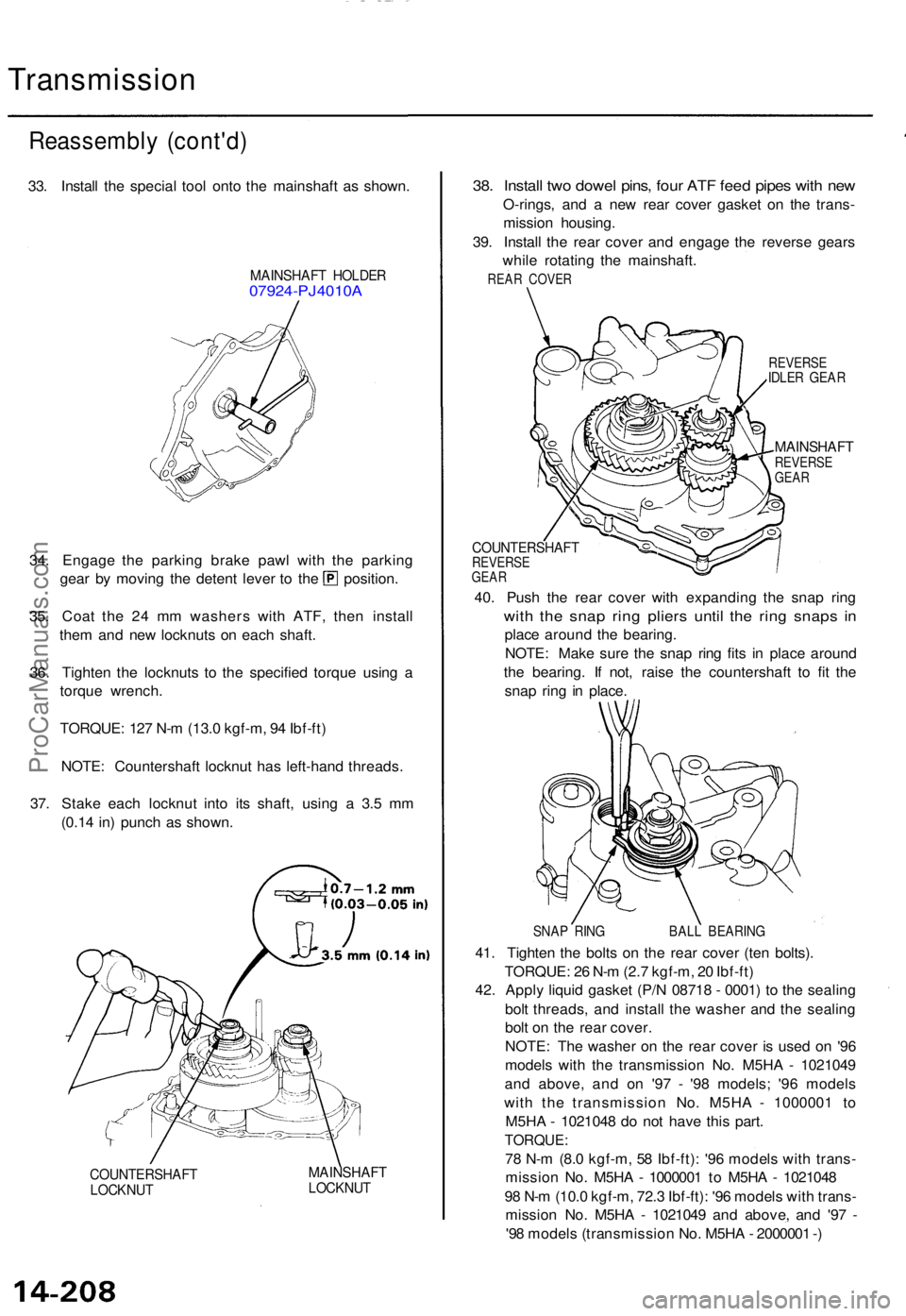
33. Instal l th e specia l too l ont o th e mainshaf t a s shown .
MAINSHAF T HOLDE R07924-PJ4010 A
34. Engag e th e parkin g brak e paw l wit h th e parkin g
gear b y movin g th e deten t leve r t o th e position .
35 . Coa t th e 2 4 m m washer s wit h ATF , the n instal l
the m an d ne w locknut s o n eac h shaft .
36 . Tighte n th e locknut s t o th e specifie d torqu e usin g a
torqu e wrench .
TORQUE : 12 7 N- m (13. 0 kgf-m , 9 4 Ibf-ft )
NOTE : Countershaf t locknu t ha s left-han d threads .
37 . Stak e eac h locknu t int o it s shaft , usin g a 3. 5 m m
(0.1 4 in ) punc h a s shown .
COUNTERSHAF TLOCKNUT
MAINSHAF TLOCKNUT
38. Instal l tw o dowe l pins , fou r AT F fee d pipe s wit h ne w
O-rings , an d a ne w rea r cove r gaske t o n th e trans -
missio n housing .
39 . Instal l th e rea r cove r an d engag e th e revers e gear s
whil e rotatin g th e mainshaft .
REAR COVE R
REVERS EIDLER GEA R
MAINSHAF TREVERSEGEAR
COUNTERSHAF TREVERSEGEAR
40. Pus h th e rea r cove r wit h expandin g th e sna p rin g
with th e sna p rin g plier s unti l th e rin g snap s i n
plac e aroun d th e bearing .
NOTE : Mak e sur e th e sna p rin g fit s i n plac e aroun d
th e bearing . I f not , rais e th e countershaf t t o fi t th e
sna p rin g i n place .
SNAP RIN G BAL L BEARIN G
41. Tighte n th e bolt s o n th e rea r cove r (te n bolts) .
TORQUE : 2 6 N- m (2. 7 kgf-m , 2 0 Ibf-ft )
42 . Appl y liqui d gaske t (P/ N 0871 8 - 0001 ) t o th e sealin g
bol t threads , an d instal l th e washe r an d th e sealin g
bol t o n th e rea r cover .
NOTE : Th e washe r o n th e rea r cove r i s use d o n '9 6
model s wit h th e transmissio n No . M5H A - 102104 9
an d above , an d o n '9 7 - '9 8 models ; '9 6 model s
wit h th e transmissio n No . M5H A - 100000 1 t o
M5H A - 102104 8 d o no t hav e thi s part .
TORQUE :
78 N- m (8. 0 kgf-m , 5 8 Ibf-ft) : '9 6 model s wit h trans -
missio n No . M5H A - 100000 1 t o M5H A - 102104 8
9 8 N- m (10. 0 kgf-m , 72. 3 Ibf-ft) : '9 6 model s wit h trans -
missio n No . M5H A - 102104 9 an d above , an d '9 7 -
'9 8 model s (transmissio n No . M5H A - 200000 1 -)
ProCarManuals.com
Page 423 of 1771
Torque Converter/Driv e Plate/Rin g Gea r
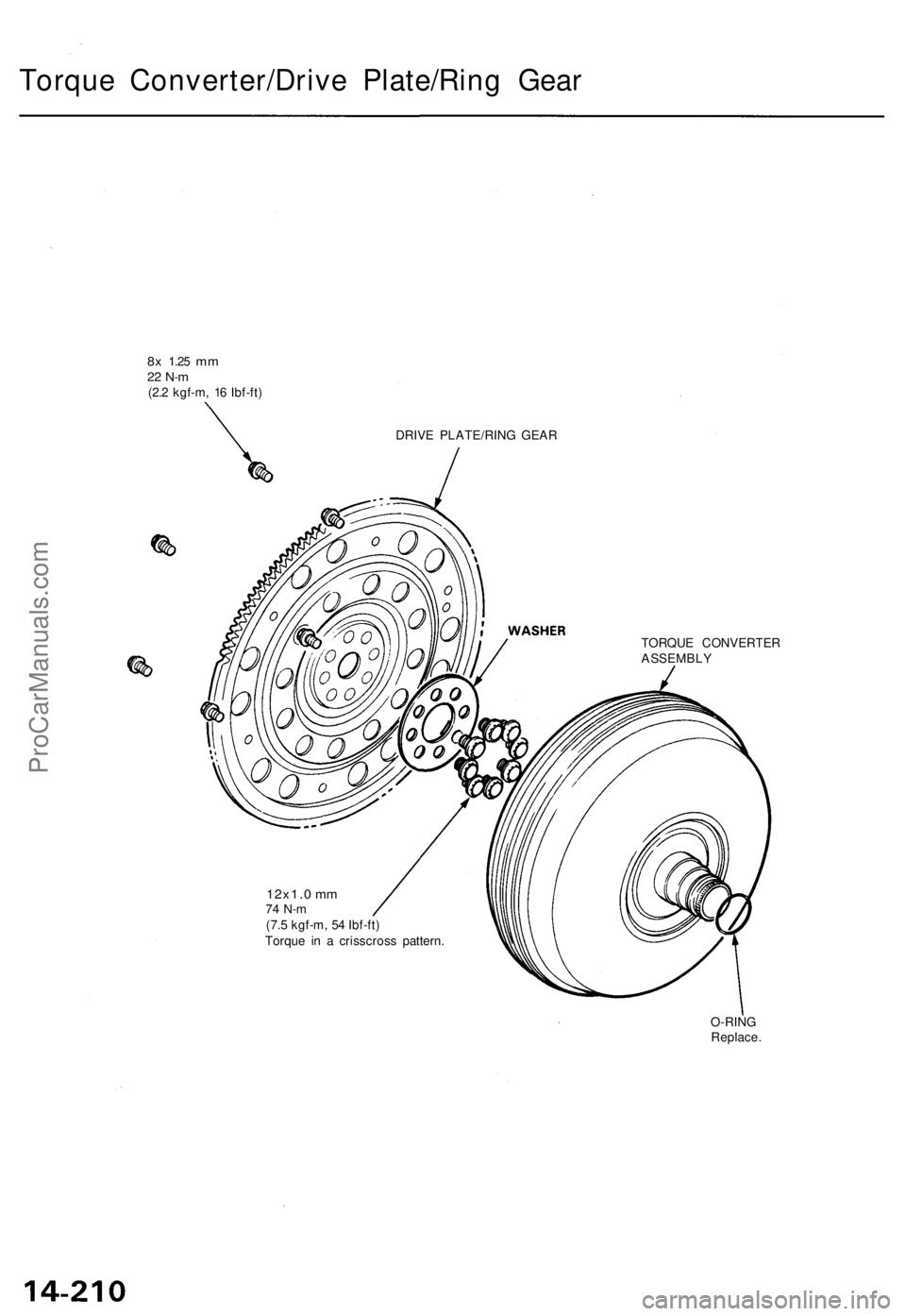
8x 1.2 5 mm22 N- m(2.2 kgf-m , 1 6 Ibf-ft )
DRIVE PLATE/RIN G GEA R
12x1. 0 m m74 N- m(7.5 kgf-m , 5 4 Ibf-ft )
Torqu e i n a crisscros s pattern . TORQU
E CONVERTE R
ASSEMBL Y
O-RIN G
Replace .
ProCarManuals.com
Page 424 of 1771
Transmission
Installation
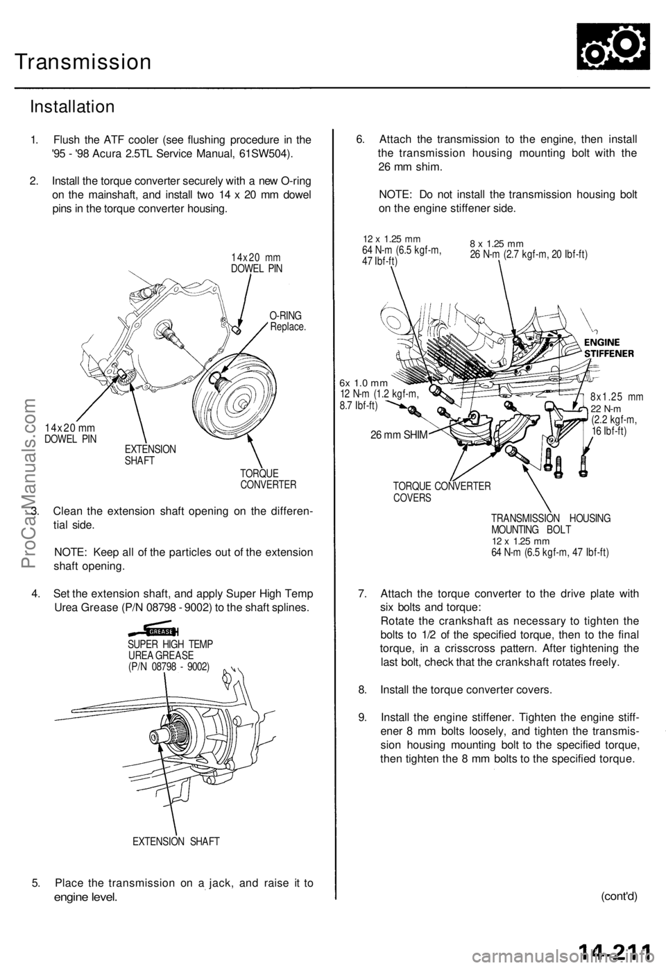
1. Flush the ATF cooler (see flushing procedure in the
'95 - '98 Acura 2.5TL Service Manual, 61SW504).
2. Install the torque converter securely with a new O-ring
on the mainshaft, and install two 14 x 20 mm dowel
pins in the torque converter housing.
14x20 mm
DOWEL PIN
14x20 mm
DOWEL PIN
O-RING
Replace.
EXTENSION
SHAFT
TORQUE
CONVERTER
3. Clean the extension shaft opening on the differen-
tial side.
NOTE: Keep all of the particles out of the extension
shaft opening.
4. Set the extension shaft, and apply Super High Temp
Urea Grease (P/N 08798 - 9002) to the shaft splines.
SUPER HIGH TEMP
UREA GREASE
(P/N 08798 - 9002)
EXTENSION SHAFT
5. Place the transmission on a jack, and raise it to
engine level.
6. Attach the transmission to the engine, then install
the transmission housing mounting bolt with the
26 mm shim.
NOTE: Do not install the transmission housing bolt
on the engine stiffener side.
12 x
1.25
mm
64 N-m (6.5 kgf-m,
47 Ibf-ft)
8 x
1.25
mm
26 N-m (2.7 kgf-m, 20 Ibf-ft)
6x 1.0 mm
12 N-m (1.2 kgf-m,
8.7 Ibf-ft)
26 mm SHIM
8x1.25 mm
22 N-m
(2.2 kgf-m,
16 Ibf-ft)
TORQUE CONVERTER
COVERS
TRANSMISSION HOUSING
MOUNTING BOLT
12 x
1.25
mm
64 N-m (6.5 kgf-m, 47 Ibf-ft)
7. Attach the torque converter to the drive plate with
six bolts and torque:
Rotate the crankshaft as necessary to tighten the
bolts to 1/2 of the specified torque, then to the final
torque, in a crisscross pattern. After tightening the
last bolt, check that the crankshaft rotates freely.
8. Install the torque converter covers.
9. Install the engine stiffener. Tighten the engine stiff-
ener 8 mm bolts loosely, and tighten the transmis-
sion housing mounting bolt to the specified torque,
then tighten the 8 mm bolts to the specified torque.
(cont'd)ProCarManuals.com
Page 448 of 1771
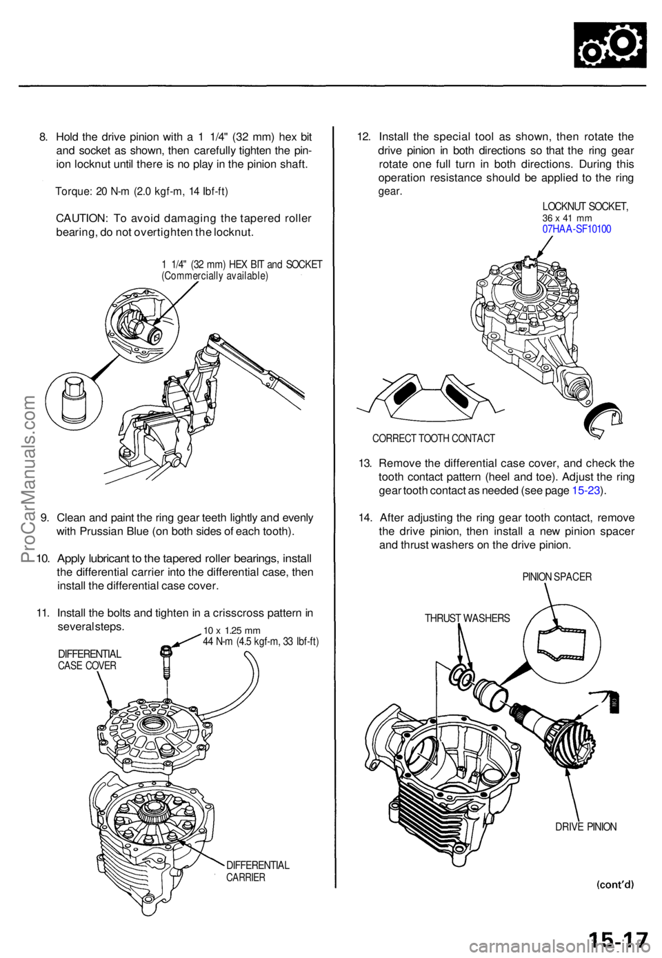
8. Hol d th e driv e pinio n wit h a 1 1/4 " (3 2 mm ) he x bi t
an d socke t a s shown , the n carefull y tighte n th e pin -
io n locknu t unti l ther e is n o pla y in th e pinio n shaft .
Torque : 2 0 N- m (2. 0 kgf-m , 1 4 Ibf-ft )
CAUTION : T o avoi d damagin g th e tapere d rolle r
bearing , d o no t overtighte n th e locknut .
1 1/4 " (3 2 mm ) HE X BI T an d SOCKE T(Commerciall y available )
9. Clea n an d pain t th e rin g gea r teet h lightl y an d evenl y
wit h Prussia n Blu e (o n bot h side s o f eac h tooth) .
10. Appl y lubrican t t o th e tapere d rolle r bearings , instal l
the differentia l carrie r int o th e differentia l case , the n
instal l th e differentia l cas e cover .
11 . Instal l th e bolt s an d tighte n in a crisscros s patter n in
severa l steps .
DIFFERENTIA LCASE COVE R
10 x 1.2 5 mm44 N- m (4. 5 kgf-m , 3 3 Ibf-ft )
DIFFERENTIA LCARRIER
12. Instal l th e specia l too l a s shown , the n rotat e th e
driv e pinio n i n bot h direction s s o tha t th e rin g gea r
rotat e on e ful l tur n i n bot h directions . Durin g thi s
operation resistanc e shoul d b e applie d t o th e rin g
gear .
LOCKNU T SOCKET ,36 x 41 m m07HA A-SF1010 0
CORREC T TOOT H CONTAC T
13. Remov e th e differentia l cas e cover , an d chec k th e
toot h contac t patter n (hee l an d toe) . Adjus t th e rin g
gea r toot h contac t a s neede d (se e pag e 15-23 ).
14 . Afte r adjustin g th e rin g gea r toot h contact , remov e
th e driv e pinion , the n instal l a ne w pinio n space r
an d thrus t washer s o n th e driv e pinion .
PINION SPACE R
THRUST WASHER S
DRIVE PINIO N
ProCarManuals.com
Page 450 of 1771
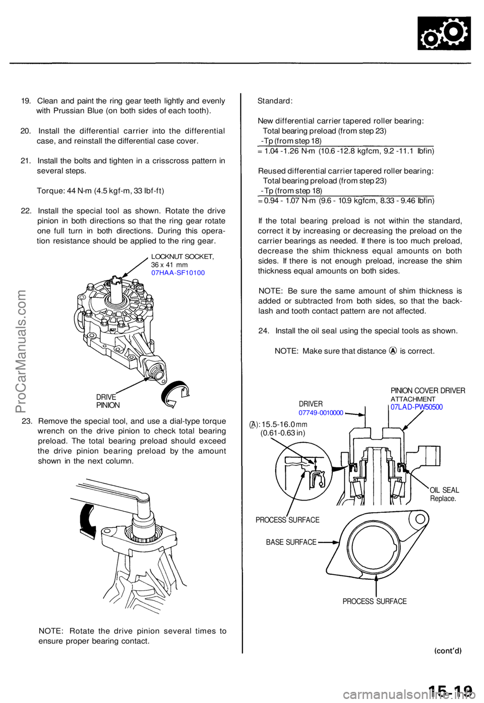
19. Clea n an d pain t th e rin g gea r teet h lightl y an d evenl y
wit h Prussia n Blu e (o n bot h side s o f eac h tooth) .
20 . Instal l th e differentia l carrie r int o th e differentia l
case , an d reinstal l th e differential case cover .
21 . Instal l th e bolt s an d tighte n i n a crisscros s patter n in
severa l steps .
Torque : 4 4 N- m (4. 5 kgf-m , 3 3 Ibf-ft )
22 . Instal l th e specia l too l a s shown . Rotat e th e driv e
pinio n i n bot h direction s s o tha t th e rin g gea r rotat e
on e ful l tur n i n bot h directions . Durin g thi s opera -
tio n resistanc e shoul d b e applie d t o th e rin g gear .
LOCKNU T SOCKET ,36 x 41 m m07HAA-SF10100
DRIV EPINIO N
23. Remov e th e specia l tool , an d us e a dial-typ e torqu e
wrenc h o n th e driv e pinio n t o chec k tota l bearin g
preload . Th e tota l bearin g preloa d shoul d excee d
th e driv e pinio n bearin g preloa d b y th e amoun t
show n i n th e nex t column .
NOTE : Rotat e th e driv e pinio n severa l time s t o
ensur e prope r bearin g contact .
Standard :
New differentia l carrie r tapere d rolle r bearing :
Tota l bearin g preloa d (fro m ste p 23 )
-Tp (fro m ste p 18 )
= 1.0 4 -1.2 6 N- m (10. 6 -12. 8 kgfcm , 9. 2 -11. 1 Ibfin )
Reuse d differentia l carrie r tapere d rolle r bearing :
Tota l bearin g preloa d (fro m ste p 23 )
- T p (fro m ste p 18 )
= 0.9 4 - 1.0 7 N- m (9. 6 - 10. 9 kgfcm , 8.3 3 - 9.4 6 Ibfin )
I f th e tota l bearin g preloa d i s no t withi n th e standard ,
correc t i t b y increasin g o r decreasin g th e preloa d o n th e
carrie r bearing s a s needed . I f ther e i s to o muc h preload ,
decreas e th e shi m thicknes s equa l amount s o n bot h
sides . I f ther e i s no t enoug h preload , increase the shi m
thicknes s equa l amount s o n bot h sides .
NOTE : B e sur e th e sam e amoun t of shi m thicknes s i s
adde d o r subtracte d fro m bot h sides , s o tha t th e back -
las h an d toot h contac t patter n ar e no t affected .
24 . Instal l th e oi l sea l usin g th e specia l tool s a s shown .
NOTE: Mak e sur e tha t distanc e i s correct .
DRIVER07749-001000 0
PINION COVE R DRIVE RATTACHMEN T07LAD-PW5050 0
(A): 15.5-16. 0 mm(0.61-0.6 3 in )
OIL SEA L
Replace .
PROCES S SURFAC E
BAS E SURFAC E
PROCESS SURFAC E
ProCarManuals.com
Page 455 of 1771
Differential Assembly
Installation
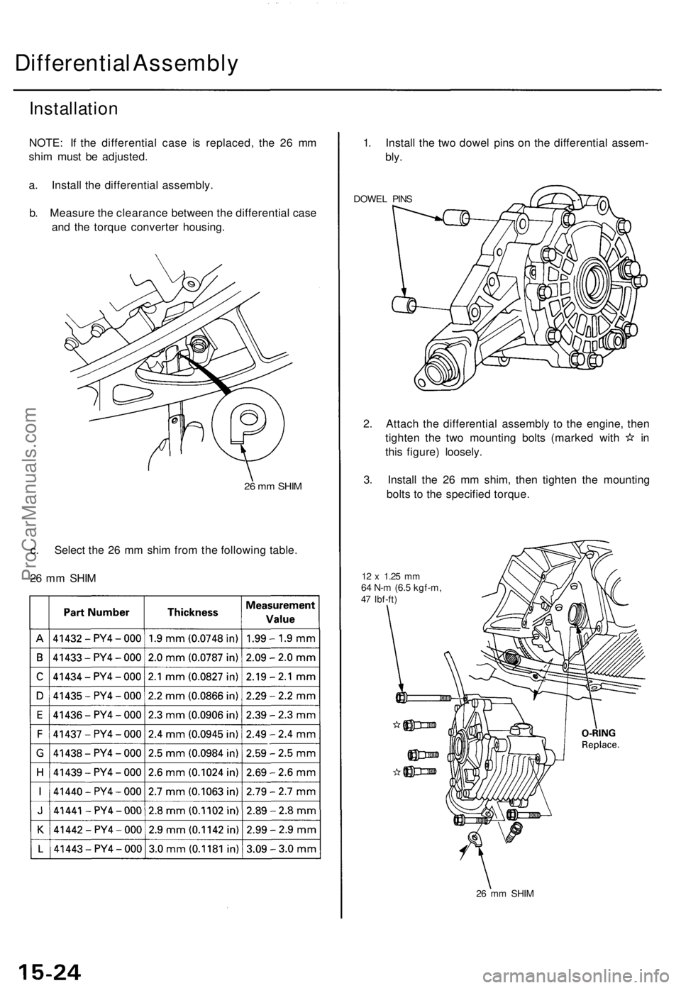
NOTE: If the differential case is replaced, the 26 mm
shim must be adjusted.
a. Install the differential assembly.
b. Measure the clearance between the differential case
and the torque converter housing.
26 mm SHIM
c. Select the 26 mm shim from the following table.
26 mm SHIM
1. Install the two dowel pins on the differential assem-
bly.
DOWEL PINS
2. Attach the differential assembly to the engine, then
tighten the two mounting bolts (marked with in
this figure) loosely.
3. Install the 26 mm shim, then tighten the mounting
bolts to the specified torque.
12 x
1.25
mm
64 N-m (6.5 kgf-m,
47 Ibf-ft)
26 mm SHIMProCarManuals.com