1995 ACURA TL torque
[x] Cancel search: torquePage 483 of 1771
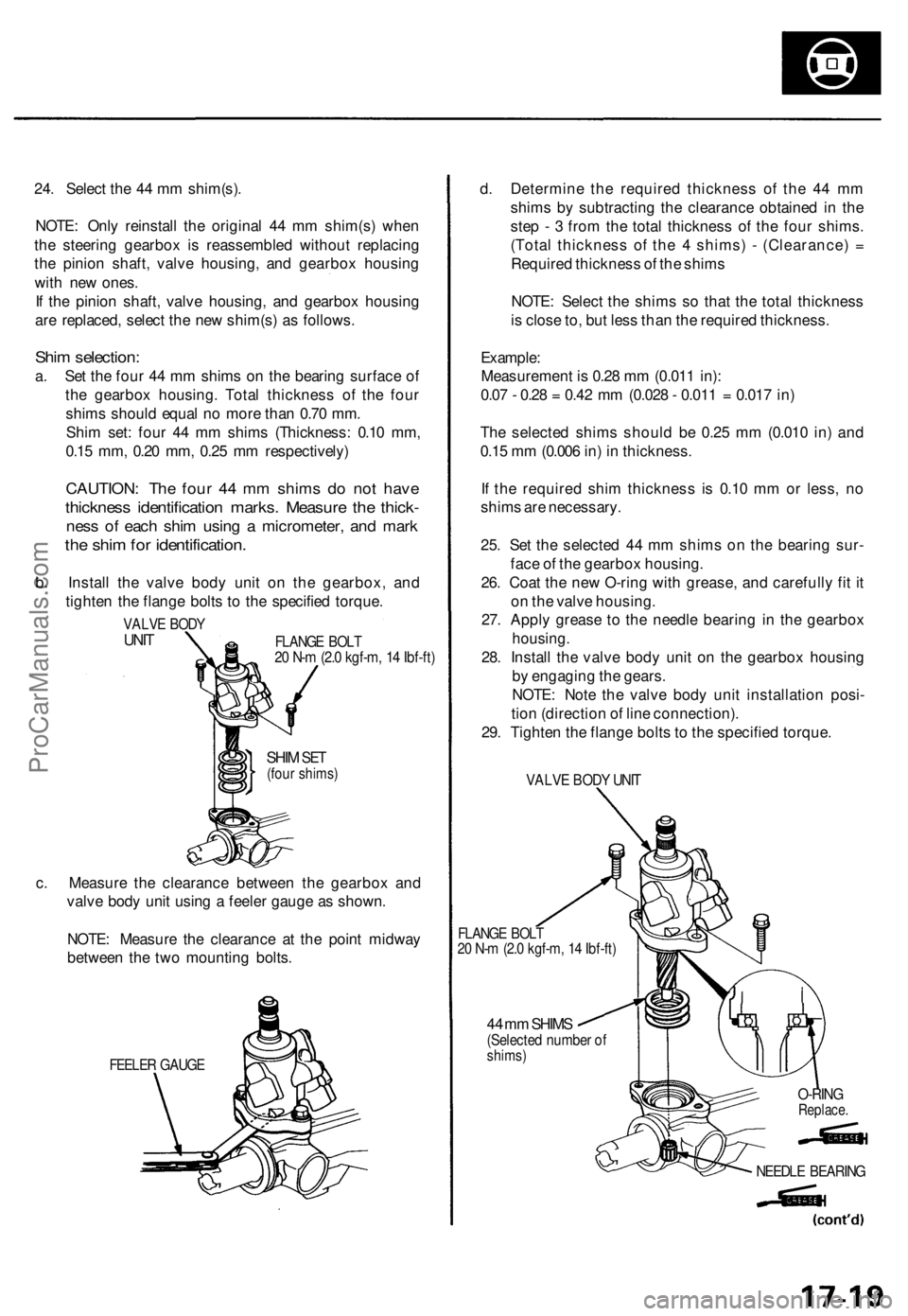
24. Selec t th e 4 4 m m shim(s) .
NOTE : Onl y reinstal l th e origina l 4 4 m m shim(s ) whe n
th e steerin g gearbo x i s reassemble d withou t replacin g
th e pinio n shaft , valv e housing , an d gearbo x housin g
wit h ne w ones .
I f th e pinio n shaft , valv e housing , an d gearbo x housin g
ar e replaced , selec t th e ne w shim(s ) a s follows .
Shim selection :
a. Se t th e fou r 4 4 m m shim s o n th e bearin g surfac e o f
th e gearbo x housing . Tota l thicknes s o f th e fou r
shim s shoul d equa l n o mor e tha n 0.7 0 mm .
Shi m set : fou r 4 4 m m shim s (Thickness : 0.1 0 mm ,
0.1 5 mm , 0.2 0 mm , 0.2 5 m m respectively )
CAUTION: Th e fou r 4 4 m m shim s d o no t hav e
thicknes s identificatio n marks . Measur e th e thick -
ness o f eac h shi m usin g a micrometer , an d mar k
the shi m fo r identification .
b. Instal l th e valv e bod y uni t o n th e gearbox , an d
tighte n th e flang e bolt s t o th e specifie d torque .
VALVE BOD YUNITFLANG E BOL T20 N- m (2. 0 kgf-m , 1 4 Ibf-ft )
SHIM SET(fou r shims )
c. Measur e th e clearanc e betwee n th e gearbo x an d
valv e bod y uni t usin g a feele r gaug e a s shown .
NOTE : Measur e th e clearanc e a t th e poin t midwa y
betwee n th e tw o mountin g bolts .
FEELE R GAUG E
d. Determin e th e require d thicknes s o f th e 4 4 m m
shim s b y subtractin g th e clearanc e obtaine d in th e
ste p - 3 fro m th e tota l thicknes s o f th e fou r shims .
(Tota l thicknes s o f th e 4 shims ) - (Clearance ) =
Require d thicknes s o f th e shim s
NOTE : Selec t th e shim s s o tha t th e tota l thicknes s
i s clos e to , bu t les s tha n th e require d thickness .
Example :
Measuremen t i s 0.2 8 m m (0.01 1 in) :
0.0 7 - 0.2 8 = 0.4 2 m m (0.02 8 - 0.01 1 = 0.01 7 in )
Th e selecte d shim s shoul d b e 0.2 5 m m (0.01 0 in ) an d
0.1 5 m m (0.00 6 in ) i n thickness .
I f th e require d shi m thicknes s i s 0.1 0 m m o r less , n o
shim s ar e necessary .
25 . Se t th e selecte d 4 4 m m shim s o n th e bearin g sur -
fac e o f th e gearbo x housing .
26 . Coa t th e ne w O-rin g wit h grease , an d carefull y fi t i t
o n th e valv e housing .
27 . Appl y greas e t o th e needl e bearin g i n th e gearbo x
housing.
28. Instal l th e valv e bod y uni t o n th e gearbo x housin g
b y engagin g th e gears .
NOTE : Not e th e valv e bod y uni t installatio n posi -
tio n (directio n o f lin e connection) .
29 . Tighte n th e flang e bolt s to th e specifie d torque .
VALVE BOD Y UNI T
FLANG E BOL T20 N- m (2. 0 kgf-m , 1 4 Ibf-ft )
44 m m SHIM S(Selecte d numbe r o fshims )
O-RINGReplace .
NEEDLE BEARIN G
ProCarManuals.com
Page 484 of 1771
Steering Gearbo x
Reassembl y (cont'd )
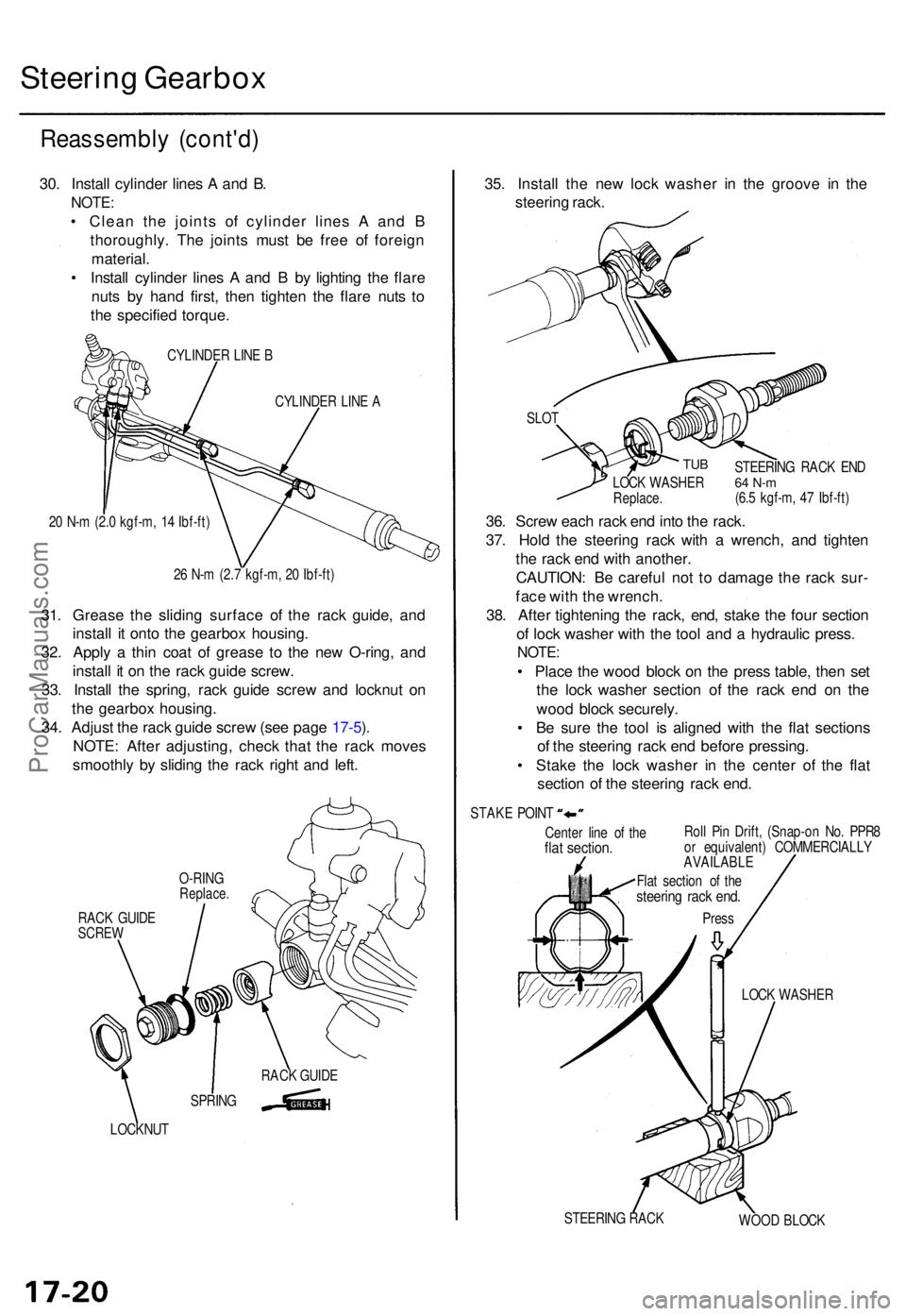
30. Instal l cylinde r line s A an d B .
NOTE :
• Clea n th e joint s o f cylinde r line s A an d B
thoroughly . Th e joint s mus t b e fre e o f foreig n
material .
• Instal l cylinde r line s A an d B by lightin g th e flar e
nut s b y han d first , the n tighte n th e flar e nut s t o
th e specifie d torque .
CYLINDE R LIN E B
CYLINDE R LIN E A
2 0 N- m (2. 0 kgf-m , 1 4 Ibf-ft )
2 6 N- m (2. 7 kgf-m , 2 0 Ibf-ft )
31. Greas e th e slidin g surfac e o f th e rac k guide , an d
instal l i t ont o th e gearbo x housing .
32 . Appl y a thi n coa t o f greas e t o th e ne w O-ring , an d
instal l i t o n th e rac k guid e screw .
33 . Instal l th e spring , rac k guid e scre w an d locknu t o n
th e gearbo x housing .
34 . Adjus t th e rac k guid e scre w (se e pag e 17-5 ).
NOTE : Afte r adjusting , chec k tha t th e rac k move s
smoothl y b y slidin g th e rac k righ t an d left .
RAC K GUID ESCRE W
LOCKNU T
35. Instal l th e ne w loc k washe r i n th e groov e i n th e
steerin g rack .
Cente r lin e o f th eflat section .Roll Pi n Drift , (Snap-o n No . PPR 8
o r equivalent ) COMMERCIALL Y
AVAILABLE
LOCK WASHE R
STEERIN G RAC K
WOOD BLOC K
SLO
T
TUB
36. Scre w eac h rac k en d int o th e rack .
37 . Hol d th e steerin g rac k wit h a wrench , an d tighte n
th e rac k en d wit h another .
CAUTION : B e carefu l no t t o damag e th e rac k sur -
fac e wit h th e wrench .
38 . Afte r tightenin g th e rack , end , stak e th e fou r sectio n
o f loc k washe r wit h th e too l an d a hydrauli c press .
NOTE:
• Plac e th e woo d bloc k o n th e pres s table , the n se t
th e loc k washe r sectio n o f th e rac k en d o n th e
woo d bloc k securely .
• B e sur e th e too l i s aligne d wit h th e fla t section s
o f th e steerin g rac k en d befor e pressing .
• Stak e th e loc k washe r i n th e cente r o f th e fla t
sectio n o f th e steerin g rac k end .
STEERIN G RAC K EN D64 N- m(6.5 kgf-m , 4 7 Ibf-ft )
LOC
K WASHE RReplace.
STAKE POIN T
Flat sectio n o f th e
steerin g rac k end .
Pres s
SPRIN GRAC
K GUID E
O-RIN
G
Replace .
ProCarManuals.com
Page 488 of 1771
Steering Gearbo x
Installatio n (cont'd )
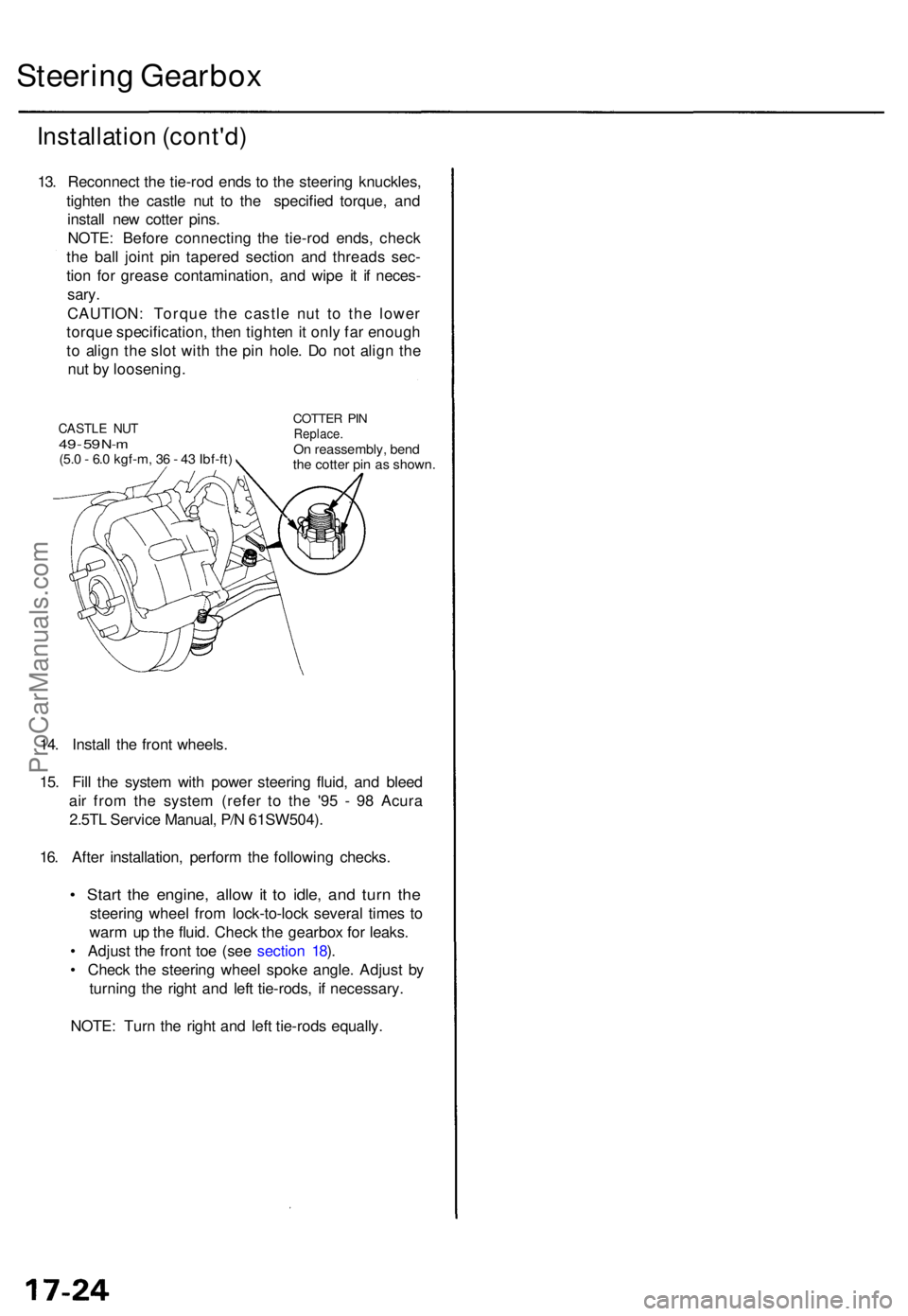
13. Reconnec t th e tie-ro d end s t o th e steerin g knuckles ,
tighte n th e castl e nu t t o th e specifie d torque , an d
instal l ne w cotte r pins .
NOTE : Befor e connectin g th e tie-ro d ends , chec k
th e bal l join t pi n tapere d sectio n an d thread s sec -
tio n fo r greas e contamination , an d wip e i t i f neces -
sary.
CAUTION : Torqu e th e castl e nu t t o th e lowe r
torqu e specification , the n tighte n it onl y fa r enoug h
t o alig n th e slo t wit h th e pi n hole . D o no t alig n th e
nu t b y loosening .
14 . Instal l th e fron t wheels .
15 . Fil l th e syste m wit h powe r steerin g fluid , an d blee d
ai r fro m th e syste m (refe r t o th e '9 5 - 9 8 Acur a
2.5T L Servic e Manual , P/ N 61SW504) .
16 . Afte r installation , perfor m th e followin g checks .
• Star t th e engine , allo w it t o idle , an d tur n th e
steerin g whee l fro m lock-to-loc k severa l time s t o
war m u p th e fluid . Chec k th e gearbo x fo r leaks .
• Adjus t th e fron t to e (se e sectio n 18 ).
• Chec k th e steerin g whee l spok e angle . Adjus t b y
turning the righ t an d lef t tie-rods , i f necessary .
NOTE : Tur n th e righ t an d lef t tie-rod s equally .
CASTLE NU T49 - 5 9 N- m(5. 0 - 6. 0 kgf-m , 3 6 - 4 3 Ibf-ft )
COTTE R PI NReplace .On reassembly , ben d
th e cotte r pi n a s shown .
ProCarManuals.com
Page 493 of 1771
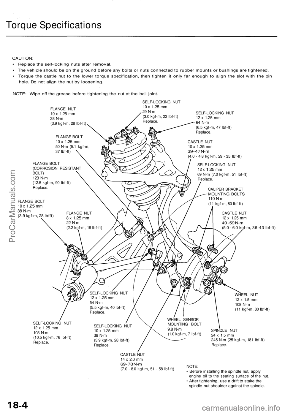
Torque Specification s
CAUTION:
• Replac e th e self-lockin g nut s afte r removal .
• Th e vehicl e shoul d b e o n th e groun d befor e an y bolt s o r nut s connecte d t o rubbe r mount s o r bushing s ar e tightened .
• Torqu e th e castl e nu t t o th e lowe r torqu e specification , the n tighte n i t onl y fa r enoug h t o alig n th e slo t wit h th e pi n
hole . D o no t alig n th e nu t b y loosening .
NOTE : Wip e of f th e greas e befor e tightenin g th e nu t a t th e bal l joint .
SELF-LOCKIN G NU T10 x 1.2 5 mm29 N- m(3.0 kgf-m , 2 2 Ibf-ft )Replace .
FLANGE BOL T10 x 1.2 5 mm38 N- m(3.9 kgf-m , 2 8 Ibfft )
SELF-LOCKIN G NU T12 x 1.2 5 mm
- 6 4 N- m
(6.5 kgf-m , 4 7 Ibf-ft )Replace .
CASTLE NU T10 x 1.2 5 mm39 - 4 7 N- m(4. 0 - 4. 8 kgf-m , 2 9 - 3 5 Ibf-ft )
SELF-LOCKIN G NU T
12 x 1.2 5 mm69 N- m (7. 0 kgf-m , 5 1 Ibf-ft )
Replace .
CALIPER BRACKE TMOUNTING BOLT S110 N- m(11 kgf-m , 8 0 Ibf-ft )
CASTL E NU T
12 x 1.2 5 mm49 - 5 9 N- m(5. 0 - 6. 0 kgf-m , 36-4 3 Ibf-ft )
SELF-LOCKIN G NU T12 x 1.2 5 mm103 N- m(10. 5 kgf-m , 7 6 Ibf-ft )Replace .
SELF-LOCKIN G NU T10 x 1.2 5 mm38 N- m(3.9 kgf-m , 2 8 Ibf-ft )Replace .
CASTLE NU T14 x 2. 0 m m69 - 7 8 N- m(7. 0 - 8. 0 kgf-m , 5 1 - 5 8 Ibf-ft ) WHEE
L NU T
12 x 1. 5 m m108 N- m(11 kgf-m , 8 0 Ibf-ft )
SPINDL E NU T
24 x 1. 5 m m245 N- m (2 5 kgf-m , 18 1 Ibf-ft )Replace .
NOTE:• Befor e installin g th e spindl e nut , appl yengin e oi l t o th e seatin g surfac e o f th e nut .• Afte r tightening , us e a drif t t o stak e th espindl e nu t shoulde r agains t th e spindle .
FLANGE NU T10 x 1.2 5 mm38 N- m(3.9 kgf-m , 2 8 Ibf-ft )
FLANG E BOL T
10 x 1.2 5 mm50 N- m (5. 1 kgf-m ,
3 7 Ibf-ft )
FLANG E NU T
8 x 1.2 5 mm22 N- m(2.2 kgf-m , 1 6 Ibf-ft )
FLANG
E BOL T
(CORROSIO N RESISTAN T
BOLT)123 N- m(12. 5 kgf-m , 9 0 Ibf-ft )Replace .
WHEEL SENSO R
MOUNTIN G BOL T
9.8 N- m(1.0 kgf-m , 7 Ibf-ft )
SELF-LOCKIN
G NU T
12 x 1.2 5 mm54 N- m(5.5 kgf-m , 4 0 Ibf-ft )Replace .
ProCarManuals.com
Page 516 of 1771
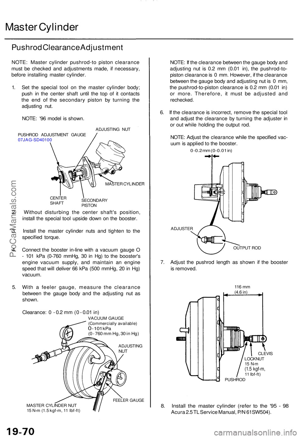
Master Cylinde r
Pushrod Clearanc e Adjustmen t
NOTE: Maste r cylinde r pushrod-t o pisto n clearanc e
mus t b e checke d an d adjustment s made , i f necessary ,
befor e installin g maste r cylinder .
1 . Se t th e specia l too l o n th e maste r cylinde r body ;
pus h i n th e cente r shaf t unti l th e to p o f i t contact s
th e en d o f th e secondar y pisto n b y turnin g th e
adjustin g nut .
NOTE : '9 6 mode l i s shown .
PUSHRO D ADJUSTMEN T GAUG E
07JAG-SD4010 0 ADJUSTIN
G NU T
MASTE R CYLINDE R
CENTERSHAFTSECONDAR YPISTON
2. Withou t disturbin g th e cente r shaft' s position ,
instal l th e specia l too l upsid e dow n o n th e booster .
3 . Instal l th e maste r cylinde r nut s an d tighte n t o th e
specifie d torque .
4 . Connec t th e booste r in-lin e wit h a vacuu m gaug e O
- 10 1 kP a (0-76 0 mmHg , 3 0 in Hg ) t o th e booster' s
engin e vacuu m supply , an d maintai n a n engin e
spee d tha t wil l delive r 6 6 kP a (50 0 mmHg , 2 0 in Hg )
vacuum .
5 . Wit h a feele r gauge , measur e th e clearanc e
betwee n th e gaug e bod y an d th e adjustin g nu t a s
shown .
Clearance : 0 - 0.2 m m (0 - 0.0 1 in )
VACUU M GAUG E
(Commerciall y available )
0 - 101 kP a(0 - 76 0 m m Hg , 3 0 in Hg )
ADJUSTIN GNUT
FEELE R GAUG EMASTE R CYLINDE R NU T
1 5 N- m (1. 5 kgf-m , 1 1 Ibf-ft )
NOTE : I f th e clearanc e betwee n th e gaug e bod y an d
adjustin g nu t i s 0. 2 m m (0.0 1 in) , th e pushrod-to -
pisto n clearanc e is 0 mm . However , i f th e clearanc e
betwee n th e gaug e bod y an d adjustin g nu t i s 0 mm ,
th e pushrod-to-pisto n clearanc e is 0. 2 m m (0.0 1 in )
o r more . Therefore , i t mus t b e adjuste d an d
rechecked .
6. I f th e clearanc e is incorrect , remov e th e specia l too l
an d adjus t th e clearanc e b y turnin g th e adjuste r i n
o r ou t whil e holdin g th e outpu t rod .
NOTE : Adjus t th e clearanc e whil e th e specifie d vac -
uu m is applie d t o th e booster .
0 -0. 2 m m (0-0.0 1 in )
ADJUSTE R
OUTPUT RO D
7. Adjus t th e pushro d lengt h a s show n i f th e booste r
i s removed .
116 m m(4.6 in)
8. Instal l th e maste r cylinde r (refe r t o th e '9 5 - 9 8
Acur a 2. 5 T L Servic e Manual , P/ N 61SW504) .
LOCKNUT15 N- m(1.5 kgf-m ,11 Ibf-ft )
CLEVI S
PUSHRO D
ProCarManuals.com
Page 558 of 1771
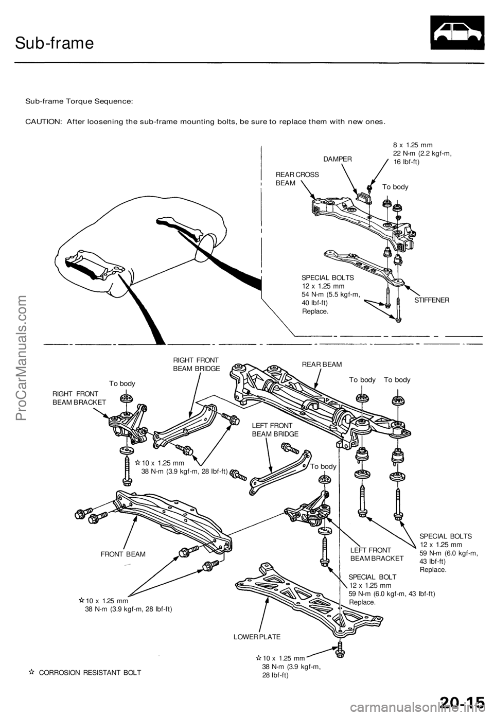
Sub-frame
Sub-frame Torque Sequence:
CAUTION: After loosening the sub-frame mounting bolts, be sure to replace them with new ones.
REAR CROSS
BEAM
DAMPER
8 x
1.25
mm
22 N-m (2.2 kgf-m,
16 Ibf-ft)
SPECIAL BOLTS
12 x
1.25
mm
54 N-m (5.5 kgf-m,
40 Ibf-ft)
Replace.
STIFFENER
RIGHT FRONT
BEAM BRIDGE
REAR BEAM
To body
To body To body
RIGHT FRONT
BEAM BRACKET
10 x
1.25
mm
38 N-m (3.9 kgf-m, 28 Ibf-ft)
SPECIAL BOLT
12 x
1.25
mm
59 N-m (6.0 kgf-m, 43 Ibf-ft)
Replace.
SPECIAL BOLTS
12 x
1.25
mm
59 N-m (6.0 kgf-m,
43 Ibf-ft)
Replace.
CORROSION RESISTANT BOLT
10 x
1.25
mm
38 N-m (3.9 kgf-m,
28 Ibf-ft)
To body
LEFT FRONT
BEAM BRIDGE
To body
10 x
1.25
mm
38 N-m (3.9 kgf-m, 28 Ibf-ft)
FRONT BEAM
LEFT FRONT
BEAM BRACKET
LOWER PLATEProCarManuals.com
Page 585 of 1771
Check for Wear and Damage
The starter should crank the engine smoothly and steadily.
If the starter engages, but cranks the engine erratically,
remove it, and inspect the starter drive gear and torque
converter ring gear for damage.
• Check the drive gear overrunning clutch for binding
or slipping when the armature is rotated with the
drive gear held. If the clutch is damaged, replace the
clutch assembly.
Check Cranking Voltage and Current Draw
Cranking voltage should be no less than 8.0 volts.
Current draw should be no more than 450 amperes.
If cranking voltage is too low, or current draw too high,
check for:
Dead or low battery
Open circuit in starter armature commutator segments
Starter armature dragging
Shorted armature winding
Excessive drag in engine
Check Cranking rpm
Engine speed during cranking should be above 100 rpm.
If speed is too low, check for:
Loose battery or starter terminals
Excessively worn starter brushes
Open circuit in commutator segments
Dirty or damaged helical spline or drive gear
Defective drive gear overrunning clutch
Check Starter Disengagement
With the shift lever in or , turn the ignition switch to
"START (III)", and release to "ON (II)". The starter drive
gear should disengage from the flywheel ring gear when
you release the key.
If the drive gear hangs upon the flywheel ring gear, check
for:
• Solenoid plunger and switch malfunction
• Dirty drive gear assembly or damaged overrunning
clutchProCarManuals.com
Page 667 of 1771
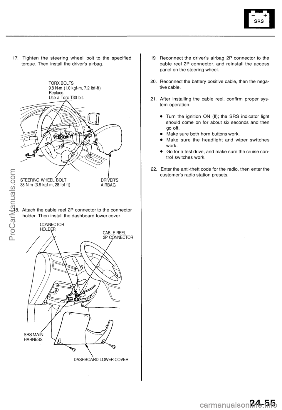
17. Tighten the steering wheel bolt to the specified
torque. Then install the driver's airbag.
TORX BOLTS
9.8 N-m (1.0 kgf-m, 7.2 Ibf-ft)
Replace.
Use a Torx T30 bit.
STEERING WHEEL BOLT
38 N-m (3.9 kgf-m, 28 Ibf-ft)
DRIVER'S
AIRBAG
18. Attach the cable reel 2P connector to the connector
holder. Then install the dashboard lower cover.
CONNECTOR
HOLDER
CABLE REEL
2P CONNECTOR
SRS
MAIN
HARNESS
DASHBOARD LOWER COVER
19. Reconnect the driver's airbag 2P connector to the
cable reel 2P connector, and reinstall the access
panel on the steering wheel.
20. Reconnect the battery positive cable, then the nega-
tive cable.
21. After installing the cable reel, confirm proper sys-
tem operation:
Turn the ignition ON (II); the SRS indicator light
should come on for about six seconds and then
go
off.
Make sure both horn buttons work.
Make sure the headlight and wiper switches
work.
Go for a test drive, and make sure the cruise con-
trol switches work.
22. Enter the anti-theft code for the radio, then enter the
customer's radio station presets.ProCarManuals.com