1995 ACURA TL torque
[x] Cancel search: torquePage 962 of 1771
Description
Position
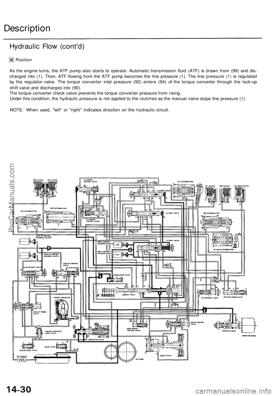
As the engine turns, the ATF pump also starts to operate. Automatic transmission fluid (ATF) is drawn from (99) and dis-
charged into (1). Then, ATF flowing from the ATF pump becomes the line pressure (1). The line pressure (1) is regulated
by the regulator valve. The torque converter inlet pressure (92) enters (94) of the torque converter through the lock-up
shift valve and discharges into (90).
The torque converter check valve prevents the torque converter pressure from rising.
Under this condition, the hydraulic pressure is not applied to the clutches as the manual valve stops line pressure (1).
NOTE: When used, "left" or "right" indicates direction on the hydraulic circuit.
Hydraulic Flow (cont'd)ProCarManuals.com
Page 965 of 1771
Position
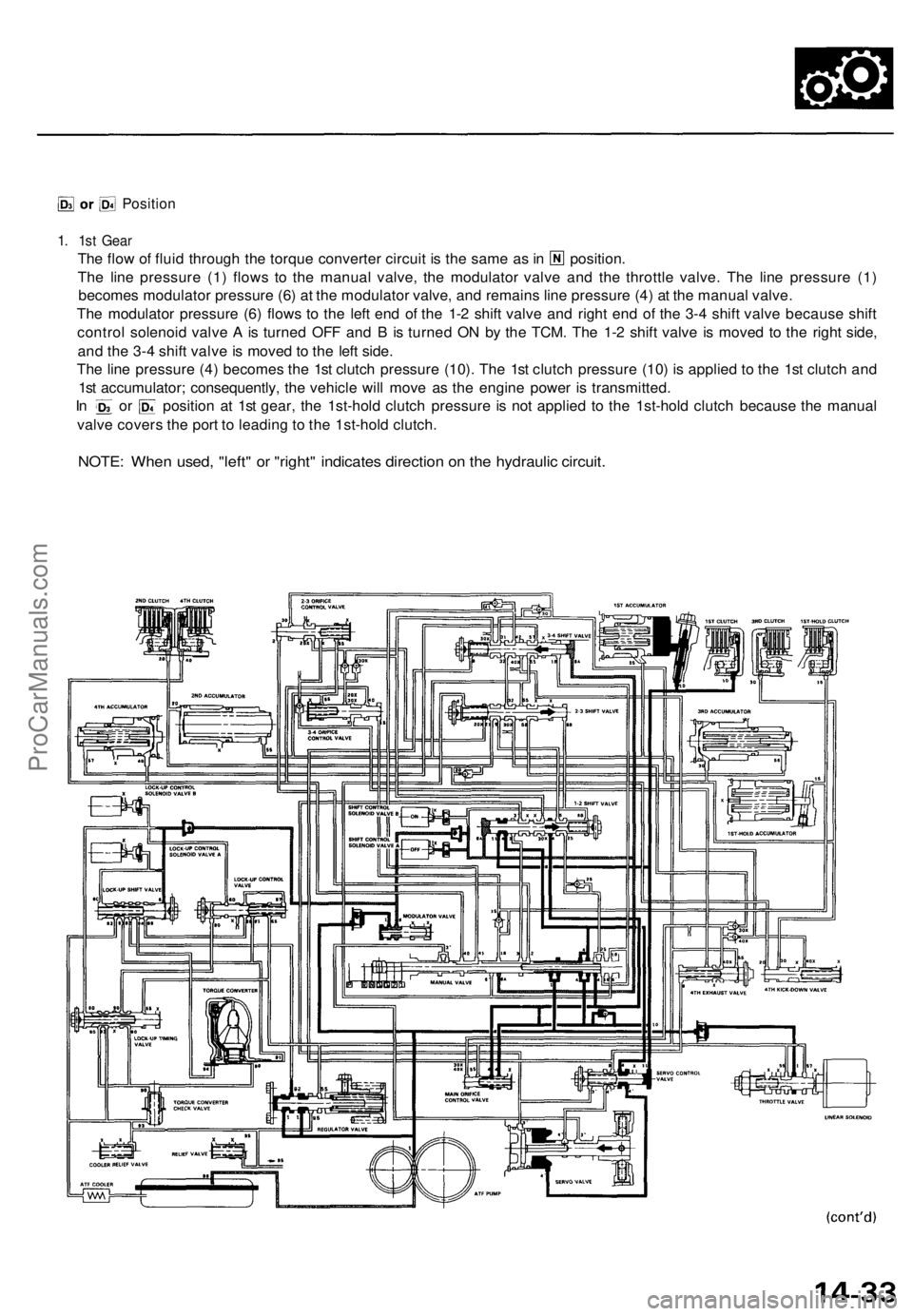
1. 1st Gear
The flow of fluid through the torque converter circuit is the same as in position.
The line pressure (1) flows to the manual valve, the modulator valve and the throttle valve. The line pressure (1)
becomes modulator pressure (6) at the modulator valve, and remains line pressure (4) at the manual valve.
The modulator pressure (6) flows to the left end of the 1-2 shift valve and right end of the 3-4 shift valve because shift
control solenoid valve A is turned OFF and B is turned ON by the TCM. The 1-2 shift valve is moved to the right side,
and the 3-4 shift valve is moved to the left side.
The line pressure (4) becomes the 1st clutch pressure (10). The 1st clutch pressure (10) is applied to the 1st clutch and
1st accumulator; consequently, the vehicle will move as the engine power is transmitted.
In or position at 1st gear, the 1st-hold clutch pressure is not applied to the 1st-hold clutch because the manual
valve covers the port to leading to the 1st-hold clutch.
NOTE: When used, "left" or "right" indicates direction on the hydraulic circuit.ProCarManuals.com
Page 969 of 1771
Position
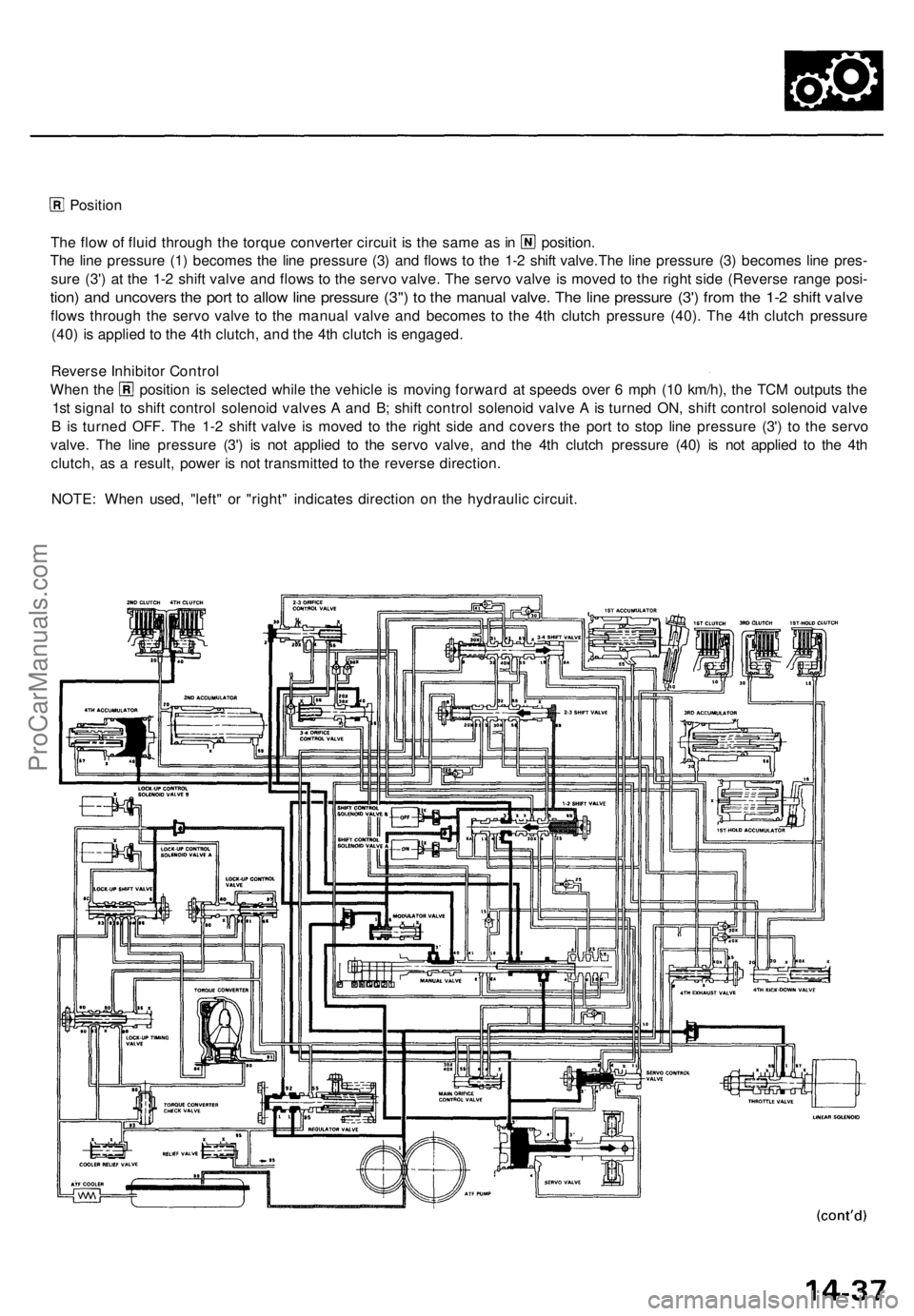
The flow of fluid through the torque converter circuit is the same as in position.
The line pressure (1) becomes the line pressure (3) and flows to the 1-2 shift valve.The line pressure (3) becomes line pres-
sure (3') at the 1-2 shift valve and flows to the servo valve. The servo valve is moved to the right side (Reverse range posi-
tion) and uncovers the port to allow line pressure (3") to the manual valve. The line pressure (3') from the 1-2 shift valve
flows through the servo valve to the manual valve and becomes to the 4th clutch pressure (40). The 4th clutch pressure
(40) is applied to the 4th clutch, and the 4th clutch is engaged.
Reverse Inhibitor Control
When the position is selected while the vehicle is moving forward at speeds over 6 mph (10 km/h), the TCM outputs the
1st signal to shift control solenoid valves A and B; shift control solenoid valve A is turned ON, shift control solenoid valve
B is turned OFF. The 1-2 shift valve is moved to the right side and covers the port to stop line pressure (3') to the servo
valve. The line pressure (3') is not applied to the servo valve, and the 4th clutch pressure (40) is not applied to the 4th
clutch, as a result, power is not transmitted to the reverse direction.
NOTE: When used, "left" or "right" indicates direction on the hydraulic circuit.ProCarManuals.com
Page 970 of 1771
Description
B Position
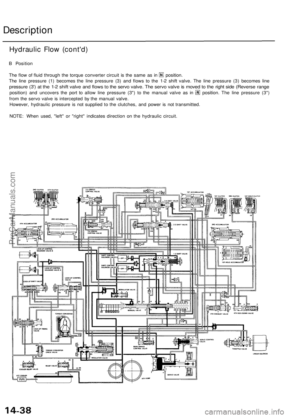
The flow of fluid through the torque converter circuit is the same as in position.
The line pressure (1) becomes the line pressure (3) and flows to the 1-2 shift valve. The line pressure (3) becomes line
pressure (3') at the 1-2 shift valve and flows to the servo valve. The servo valve is moved to the right side (Reverse range
position) and uncovers the port to allow line pressure (3") to the manual valve as in position. The line pressure (3")
from the servo valve is intercepted by the manual valve.
However, hydraulic pressure is not supplied to the clutches, and power is not transmitted.
NOTE: When used, "left" or "right" indicates direction on the hydraulic circuit.
Hydraulic Flow (cont'd)ProCarManuals.com
Page 988 of 1771
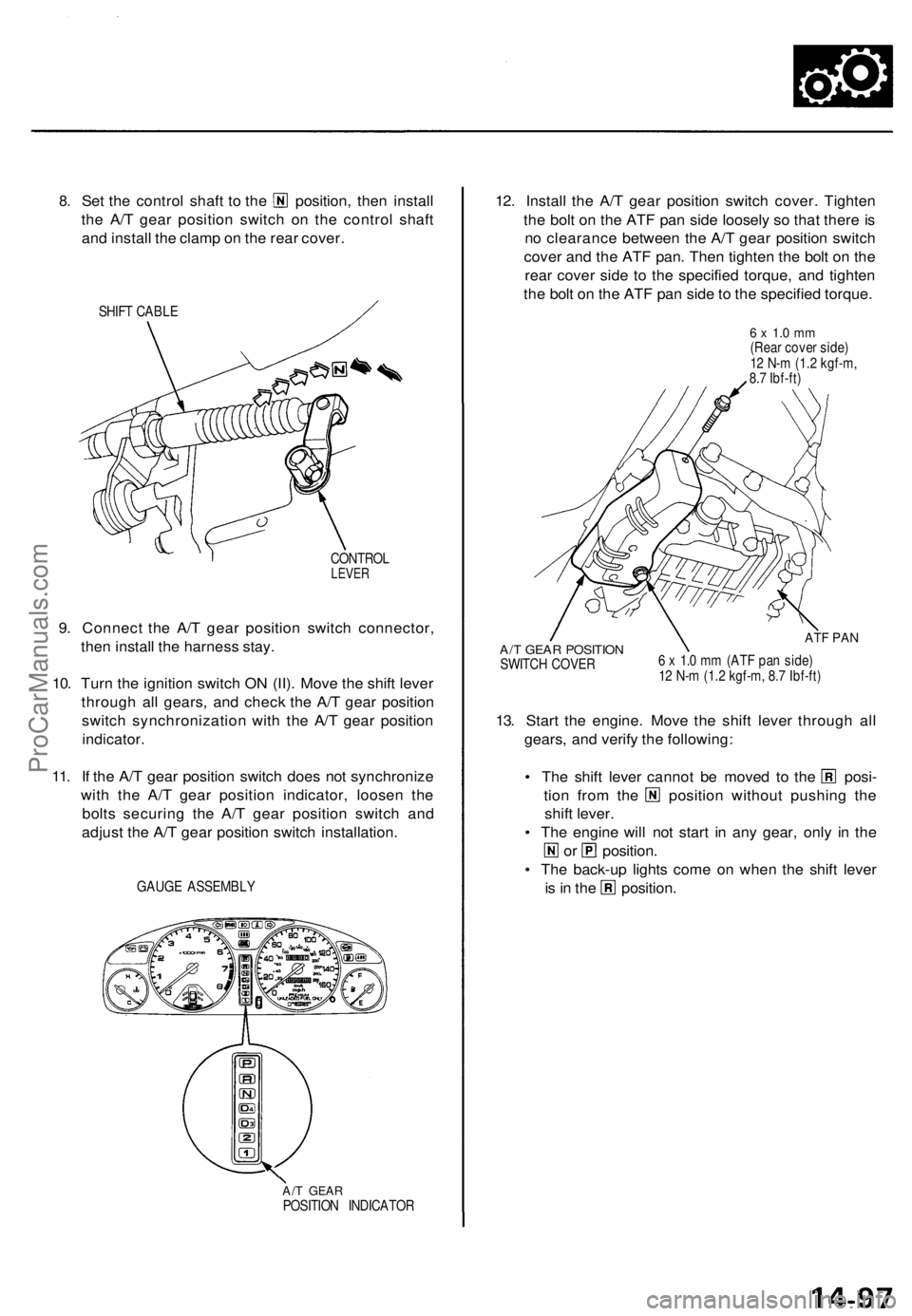
8.
Set the control shaft to the position, then install
the A/T gear position switch on the control shaft
and install the clamp on the rear cover.
SHIFT CABLE
CONTROL
LEVER
9. Connect the A/T gear position switch connector,
then install the harness stay.
10. Turn the ignition switch ON (II). Move the shift lever
through all gears, and check the A/T gear position
switch synchronization with the A/T gear position
indicator.
11. If the A/T gear position switch does not synchronize
with the A/T gear position indicator, loosen the
bolts securing the A/T gear position switch and
adjust the A/T gear position switch installation.
GAUGE ASSEMBLY
A/T GEAR
POSITION INDICATOR
12. Install the A/T gear position switch cover. Tighten
the bolt on the ATF pan side loosely so that there is
no clearance between the A/T gear position switch
cover and the ATF pan. Then tighten the bolt on the
rear cover side to the specified torque, and tighten
the bolt on the ATF pan side to the specified torque.
6 x 1.0 mm
(Rear cover side)
12 N-m (1.2 kgf-m,
8.7 Ibf-ft)
A/T GEAR POSITION
SWITCH COVER
ATF PAN
6 x 1.0 mm (ATF pan side)
12 N-m (1.2 kgf-m, 8.7 Ibf-ft)
13. Start the engine. Move the shift lever through all
gears, and verify the following:
• The shift lever cannot be moved to the posi-
tion from the position without pushing the
shift lever.
• The engine will not start in any gear, only in the
or position.
• The back-up lights come on when the shift lever
is in the position.ProCarManuals.com
Page 997 of 1771
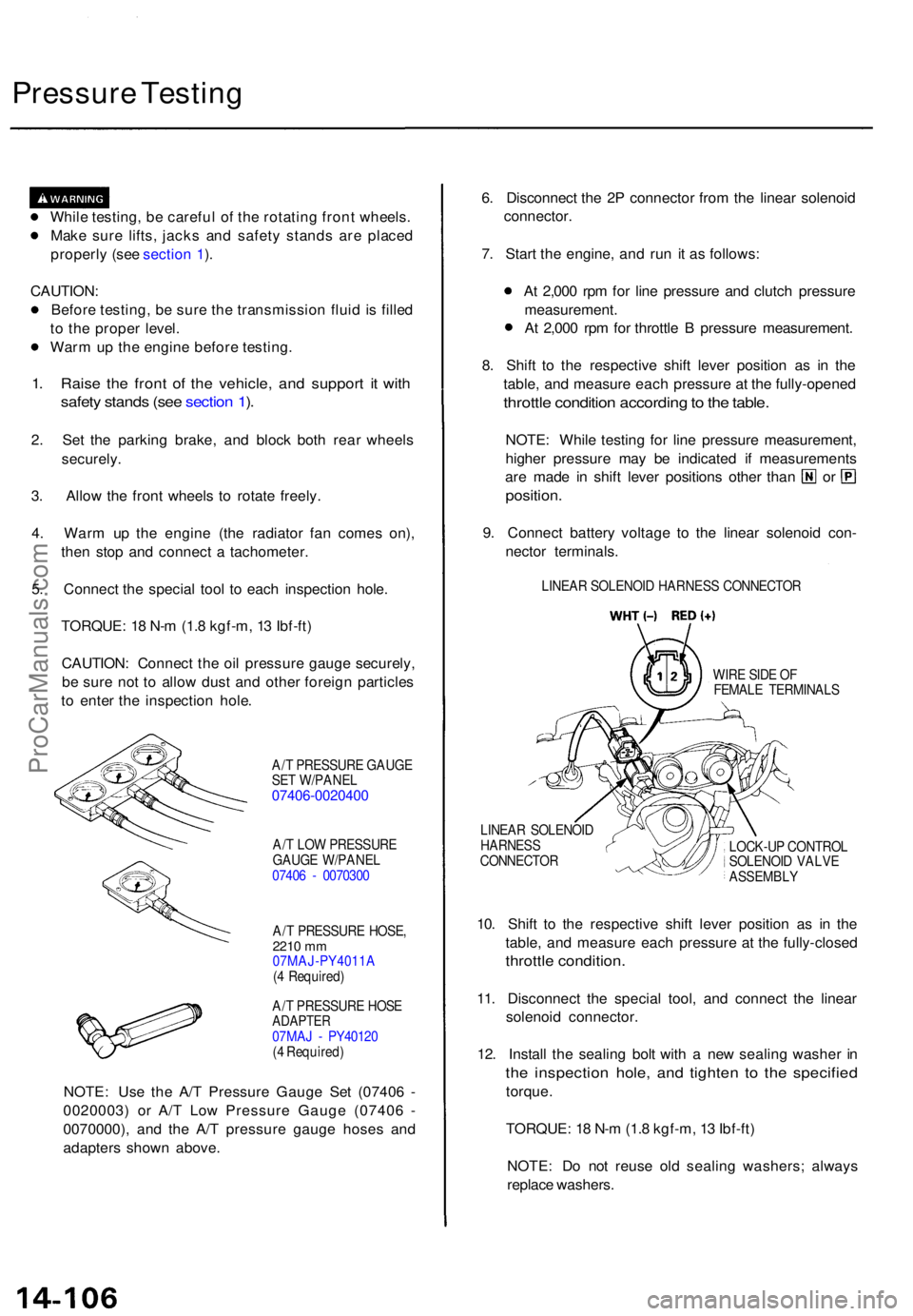
Pressure Testin g
While testing , b e carefu l o f th e rotatin g fron t wheels .
Mak e sur e lifts , jack s an d safet y stand s ar e place d
properl y (se e sectio n 1 ).
CAUTION :
Befor e testing , b e sur e th e transmissio n flui d is fille d
t o th e prope r level .
War m u p th e engin e befor e testing .
1. Rais e th e fron t o f th e vehicle , an d suppor t i t wit h
safet y stand s (se e sectio n 1 ).
2 . Se t th e parkin g brake , an d bloc k bot h rea r wheel s
securely .
3. Allo w th e fron t wheel s t o rotat e freely .
4 . War m u p th e engin e (th e radiato r fa n come s on) ,
the n sto p an d connec t a tachometer .
5 . Connec t th e specia l too l t o eac h inspectio n hole .
TORQUE : 1 8 N- m (1. 8 kgf-m , 1 3 Ibf-ft )
CAUTION : Connec t th e oi l pressur e gaug e securely ,
b e sur e no t t o allo w dus t an d othe r foreig n particle s
t o ente r th e inspectio n hole .
A/T PRESSUR E GAUG E
SE T W/PANE L
07406-002040 0
A/T LO W PRESSUR E
GAUG E W/PANE L
0740 6 - 007030 0
A/ T PRESSUR E HOSE ,
2210 mm07MAJ-PY4011 A
( 4 Required )
A/ T PRESSUR E HOS E
ADAPTE R07MAJ - PY4012 0
( 4 Required )
NOTE: Us e th e A/ T Pressur e Gaug e Se t (0740 6 -
0020003 ) o r A/ T Lo w Pressur e Gaug e (0740 6 -
0070000) , an d th e A/ T pressur e gaug e hose s an d
adapter s show n above . 6
. Disconnec t th e 2 P connecto r fro m th e linea r solenoi d
connector .
7 . Star t th e engine , an d ru n i t a s follows :
A t 2,00 0 rp m fo r lin e pressur e an d clutc h pressur e
measurement .
A t 2,00 0 rp m fo r throttl e B pressur e measurement .
8 . Shif t t o th e respectiv e shif t leve r positio n a s i n th e
table , an d measur e eac h pressur e a t th e fully-opene d
throttle conditio n accordin g to th e table .
NOTE : Whil e testin g fo r lin e pressur e measurement ,
highe r pressur e ma y b e indicate d i f measurement s
are mad e i n shif t leve r position s othe r tha n o r
position .
9. Connec t batter y voltag e t o th e linea r solenoi d con -
necto r terminals .
LINEAR SOLENOI D HARNES S CONNECTO R
WIR E SID E O F
FEMAL E TERMINAL S
LINEA R SOLENOI D
HARNES S
CONNECTO R LOCK-U
P CONTRO L
SOLENOI D VALV E
ASSEMBL Y
10. Shif t t o th e respectiv e shif t leve r positio n a s i n th e
table , an d measur e eac h pressur e a t th e fully-close d
throttle condition .
11. Disconnec t th e specia l tool , an d connec t th e linea r
solenoi d connector .
12 . Instal l th e sealin g bol t wit h a ne w sealin g washe r i n
th e inspectio n hole , an d tighte n t o th e specifie d
torque.
TORQUE : 1 8 N- m (1. 8 kgf-m , 1 3 Ibf-ft )
NOTE : D o no t reus e ol d sealin g washers ; alway s
replac e washers .
ProCarManuals.com
Page 1005 of 1771
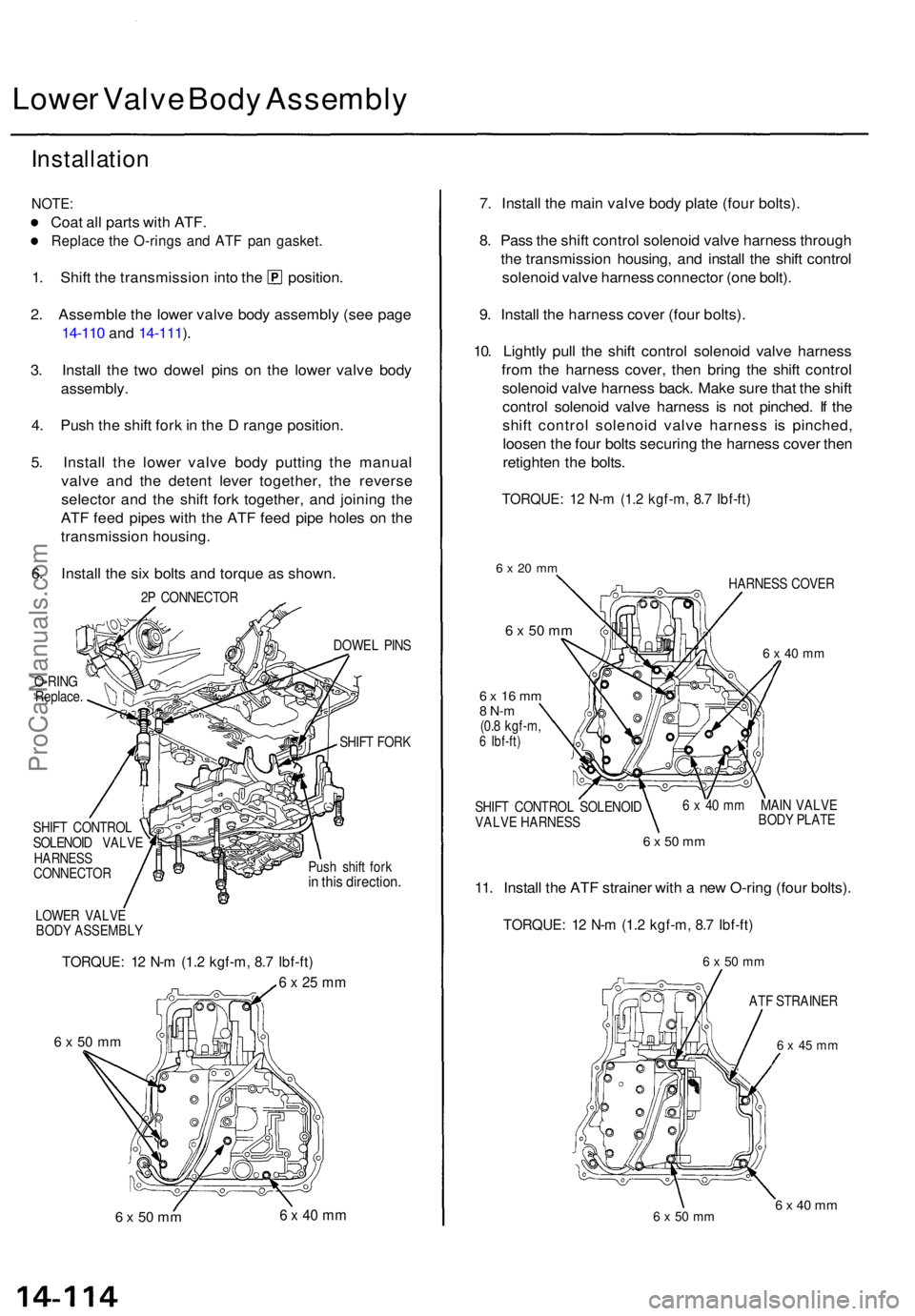
Lower Valv e Bod y Assembl y
Installatio n
NOTE:
Coat al l part s wit h ATF .
Replac e th e O-ring s an d AT F pa n gasket .
1. Shif t th e transmissio n int o th e position .
2 . Assembl e th e lowe r valv e bod y assembl y (se e pag e
14-11 0 an d 14-111 ).
3 . Instal l th e tw o dowe l pin s o n th e lowe r valv e bod y
assembly .
4 . Pus h th e shif t for k in th e D rang e position .
5 . Instal l th e lowe r valv e bod y puttin g th e manua l
valv e an d th e deten t leve r together , th e revers e
selecto r an d th e shif t for k together , an d joinin g th e
AT F fee d pipe s wit h th e AT F fee d pip e hole s o n th e
transmissio n housing .
6 . Instal l th e si x bolt s an d torqu e a s shown .
2P CONNECTO R
O-RIN G
Replace . DOWE
L PIN S
SHIF T FOR K
SHIF T CONTRO L
SOLENOI D VALV E
HARNES S
CONNECTO R Pus
h shif t for k
in thi s direction .
LOWER VALV E
BOD Y ASSEMBL Y
TORQUE: 1 2 N- m (1. 2 kgf-m , 8. 7 Ibf-ft )
6 x 25 m m
6 x 5 0 m m
6 x 50 m m 6 x 40 m m
7. Instal l th e mai n valv e bod y plat e (fou r bolts) .
8 . Pas s th e shif t contro l solenoi d valv e harnes s throug h
th e transmissio n housing , an d instal l th e shif t contro l
solenoi d valv e harnes s connecto r (on e bolt) .
9 . Instal l th e harnes s cove r (fou r bolts) .
10 . Lightl y pul l th e shif t contro l solenoi d valv e harnes s
fro m th e harnes s cover , the n brin g th e shif t contro l
solenoi d valv e harnes s back . Mak e sur e tha t th e shif t
contro l solenoi d valv e harnes s i s no t pinched . I f th e
shif t contro l solenoi d valv e harnes s i s pinched ,
loose n th e fou r bolt s securin g th e harnes s cove r the n
retighte n th e bolts .
TORQUE : 1 2 N- m (1. 2 kgf-m , 8. 7 Ibf-ft )
6 x 20 m m
6 x 50 mm
6 x 1 6 m m8 N- m(0.8 kgf-m ,6 Ibf-ft )
SHIFT CONTRO L SOLENOI D
VALV E HARNES S HARNES
S COVE R
6 x 40 m m
6 x 40 m m MAI N VALV E
BOD Y PLAT E
6 x 50 m m
11. Instal l th e AT F straine r wit h a ne w O-rin g (fou r bolts) .
TORQUE : 1 2 N- m (1. 2 kgf-m , 8. 7 Ibf-ft )
6 x 50 m m
AT F STRAINE R
6 x 4 5 m m
6 x 50 m m6 x 40 m m
ProCarManuals.com
Page 1006 of 1771
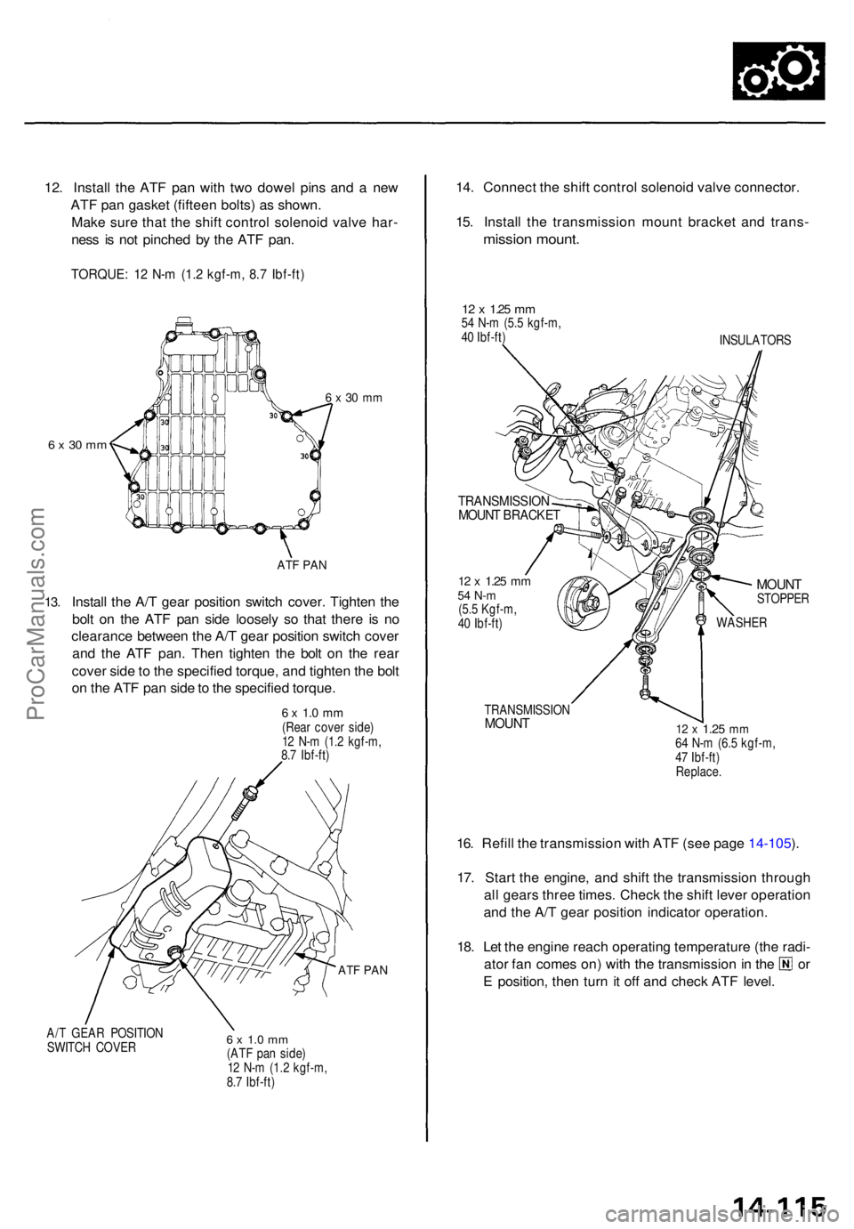
12. Instal l th e AT F pa n wit h tw o dowe l pin s an d a ne w
AT F pa n gaske t (fiftee n bolts ) a s shown .
Mak e sur e tha t th e shif t contro l solenoi d valv e har -
nes s i s no t pinche d b y th e AT F pan .
TORQUE : 1 2 N- m (1. 2 kgf-m , 8. 7 Ibf-ft )
6 x 3 0 m m
6 x 30 m m
13.
AT F PA N
Instal l th e A/ T gea r positio n switc h cover . Tighte n th e
bol t o n th e AT F pa n sid e loosel y s o tha t ther e i s n o
clearanc e betwee n th e A/ T gea r positio n switc h cove r
an d th e AT F pan . The n tighte n th e bol t o n th e rea r
cove r sid e to th e specifie d torque , an d tighte n th e bol t
o n th e AT F pa n sid e to th e specifie d torque .
6 x 1. 0 m m(Rea r cove r side )
1 2 N- m (1. 2 kgf-m ,
8. 7 Ibf-ft )
ATF PA N
A/T GEA R POSITIO N
SWITC H COVE R6 x 1. 0 m m(AT F pa n side )
1 2 N- m (1.2 kgf-m ,
8. 7 Ibf-ft )
14. Connec t th e shif t contro l solenoi d valv e connector .
15 . Instal l th e transmissio n moun t bracke t an d trans -
mission mount .
12 x 1.2 5 mm54 N- m (5. 5 kgf-m ,
4 0 Ibf-ft )
INSULATORS
TRANSMISSIO NMOUNT BRACKE T
12 x 1.2 5 mm54 N- m(5.5 Kgf-m ,
4 0 Ibf-ft )
MOUN TSTOPPE R
WASHER
TRANSMISSIO NMOUNT12 x 1.2 5 mm64 N- m (6. 5 kgf-m ,
4 7 Ibf-ft )
Replace .
16. Refil l th e transmissio n wit h AT F (se e pag e 14-105 ).
17 . Star t th e engine , an d shif t th e transmissio n throug h
al l gear s thre e times . Chec k th e shif t leve r operatio n
an d th e A/ T gea r positio n indicato r operation .
18 . Le t th e engin e reac h operatin g temperatur e (th e radi -
ator fa n come s on ) wit h th e transmissio n in th e o r
E position , the n tur n i t of f an d chec k AT F level .
ProCarManuals.com