Page 1078 of 1771
Torque Converter/Driv e Plate/Rin g Gea r
DRIVE PLATE/RIN G GEA R
6 x 1. 0 m m12 N- m(1.2 kgf-m , 8. 7 Ibf-ft )
12 x 1. 0 m m74 N- m (7. 5 kgf-m , 5 4 Ibf-ft )
Torqu e i n a crisscros s pattern .
O-RIN G
Replace . TORQU
E CONVERTE R
ASSEMBL Y
WASHE
R
ProCarManuals.com
Page 1079 of 1771
Transmission
Installation
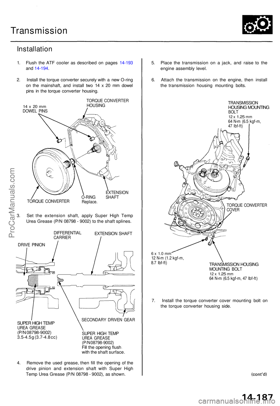
1. Flus h th e AT F coole r a s describe d o n page s 14-19 3
an d 14-194 .
2 . Instal l th e torqu e converte r securel y wit h a ne w O-rin g
o n th e mainshaft , an d instal l tw o 1 4 x 2 0 m m dowe l
pin s i n th e torqu e converte r housing .
14 x 20 m mDOWE L PIN S
TORQU E CONVERTE RHOUSING
TORQUE CONVERTE RO-RINGReplace .
EXTENSIO NSHAFT
3. Se t th e extensio n shaft , appl y Supe r Hig h Tem p
Ure a Greas e (P/ N 0879 8 - 9002 ) t o th e shaf t splines .
DIFFERENTIA LCARRIEREXTENSIO N SHAF T
DRIVE PINIO N
5. Plac e th e transmissio n o n a jack , an d rais e t o th e
engin e assembl y level .
6 . Attac h th e transmissio n o n th e engine , the n instal l
th e transmissio n housin g mountin g bolts .
TRANSMISSIO NHOUSING MOUNTIN GBOLT12 x 1.2 5 mm64 N- m (6. 5 kgf-m ,47 Ibf-ft )
TORQU E CONVERTE RCOVER
6 x 1. 0 m m12 N- m (1. 2 kgf-m ,8.7 Ibf-ft )TRANSMISSIO N HOUSIN GMOUNTIN G BOL T12 x 1.2 5 mm64 N- m (6. 5 kgf-m , 4 7 Ibf-ft )
7. Instal l th e torqu e converte r cove r mountin g bol t o n
th e torqu e converte r housin g side .
SECONDAR Y DRIVE N GEA RSUPER HIG H TEM PUREA GREAS E(P/N 08798-9002 )3.5-4.5 g (3.7-4. 8 cc )SUPE R HIG H TEM PUREA GREAS E(P/N 08798-9002 )Fill th e openin g flus h
wit h th e shaf t surface .
4 . Remov e th e use d grease , the n fill the openin g o f th e
driv e pinio n an d extensio n shaf t wit h Supe r Hig h
Tem p Ure a Greas e (P/ N 0879 8 - 9002) , a s shown .
ProCarManuals.com
Page 1080 of 1771
Transmission
Installation (cont'd)
8. Install the mid mount spacer and transmission mid
mounts while raising the transmission with a jack.
TRANSMISSION
MID MOUNT
SPACER
Install in this
direction.
MID MOUNT
10 x
1.25
mm
38 N-m (3.9 kgf-m,
28 Ibf-ft)
9. Tighten the bolts using an offset wrench and a torque
wrench as shown.
MID MOUNTS
OFFSET WRENCH
(Commercially available)
TORQUE WRENCH
NOTE: When tightening the bolts using an offset wrench
and a torque wrench, the tightening torque value differs
from torque specification according to a torque wrench.
Before tightening the bolts, calculate actual torque value
by following formula.
TORQUE
WRENCH
OFFSET WRENCH
Example:
Torque Specification: 38 N-m (3.9 kgf-m, 28 Ibf-ft)
Effective Length of Torque Wrench: 0.345 (m)
Effective Length of Offset Wrench: 0.13 (m)
WASHER
MID MOUNT NUTS
10 x
1.25
mm
43 N-m (4.4 kgf-m, 32 Ibf-ft)
10. Install the mid mount nuts.ProCarManuals.com
Page 1083 of 1771
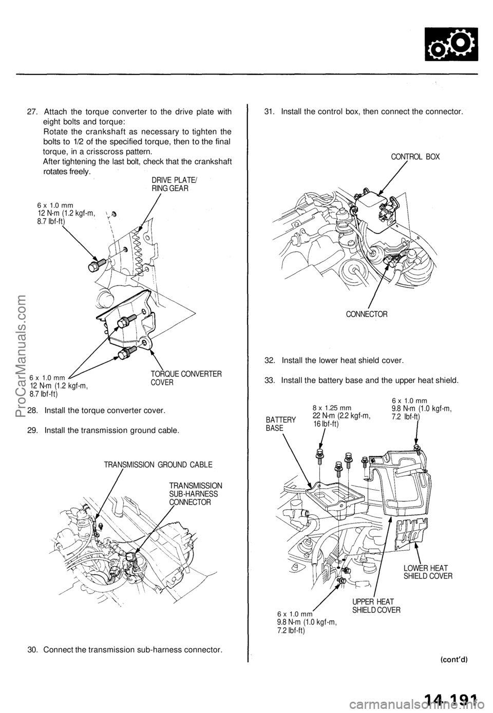
27. Attach the torque converter to the drive plate with
eight bolts and torque:
Rotate the crankshaft as necessary to tighten the
bolts to 1/2 of the specified torque, then to the final
torque, in a crisscross pattern.
After tightening the last bolt, check that the crankshaft
rotates freely.
DRIVE PLATE/
RING GEAR
6 x 1.0 mm
12 N-m (1.2 kgf-m,
8.7 Ibf-ft)
6 x 1.0 mm
12 N-m (1.2 kgf-m,
8.7 Ibf-ft)
TORQUE CONVERTER
COVER
28. Install the torque converter cover.
29. Install the transmission ground cable.
TRANSMISSION GROUND CABLE
TRANSMISSION
SUB-HARNESS
CONNECTOR
30. Connect the transmission sub-harness connector.
31. Install the control box, then connect the connector.
CONTROL BOX
CONNECTOR
32. Install the lower heat shield cover.
33. Install the battery base and the upper heat shield.
6 x 1.0 mm
9.8 N-m (1.0 kgf-m,
7.2 Ibf-ft)
LOWER HEAT
SHIELD COVER
6 x 1.0 mm
9.8 N-m (1.0 kgf-m,
7.2 Ibf-ft)
UPPER HEAT
SHIELD COVER
8 x
1.25
mm
22 N-m (2.2 kgf-m,
16 Ibf-ft)
BATTERY
BASEProCarManuals.com
Page 1091 of 1771
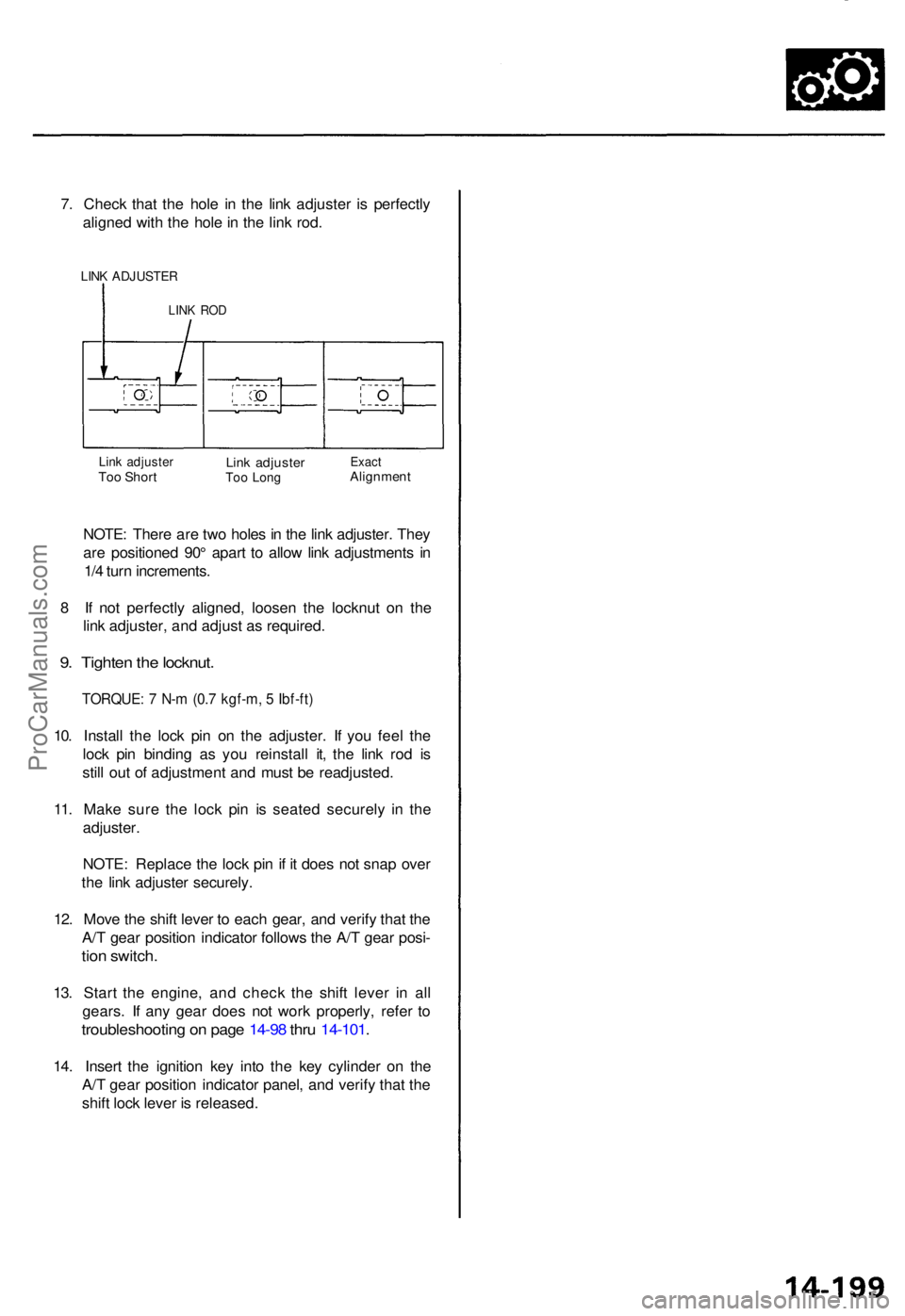
7. Chec k tha t th e hol e i n th e lin k adjuste r i s perfectl y
aligne d wit h th e hol e in th e lin k rod .
LINK ADJUSTE R
LINK RO D
Link adjuste rToo Shor tLink adjuste rToo Lon gExac tAlignmen t
NOTE: Ther e ar e tw o hole s in th e lin k adjuster . The y
ar e positione d 90 ° apar t t o allo w lin k adjustment s i n
1/ 4 tur n increments .
8 I f no t perfectl y aligned , loose n th e locknu t o n th e
lin k adjuster , an d adjus t a s required .
9. Tighte n th e locknut .
TORQUE : 7 N- m (0. 7 kgf-m , 5 Ibf-ft )
10. Instal l th e loc k pi n o n th e adjuster . I f yo u fee l th e
loc k pi n bindin g a s yo u reinstal l it , th e lin k ro d i s
stil l ou t o f adjustmen t an d mus t b e readjusted .
11 . Mak e sur e th e loc k pi n i s seate d securel y i n th e
adjuster .
NOTE : Replac e th e loc k pi n if i t doe s no t sna p ove r
th e lin k adjuste r securely .
12 . Mov e th e shif t leve r t o eac h gear , an d verif y tha t th e
A/ T gea r positio n indicato r follow s th e A/ T gea r posi -
tion switch .
13. Star t th e engine , an d chec k th e shif t leve r i n al l
gears . I f an y gea r doe s no t wor k properly , refe r t o
troubleshootin g o n pag e 14-9 8 thr u 14-101 .
14. Inser t th e ignitio n ke y int o th e ke y cylinde r o n th e
A/ T gea r positio n indicato r panel , an d verif y tha t th e
shif t loc k leve r i s released .
ProCarManuals.com
Page 1110 of 1771
Differential Assembl y
Reassembl y (cont'd )
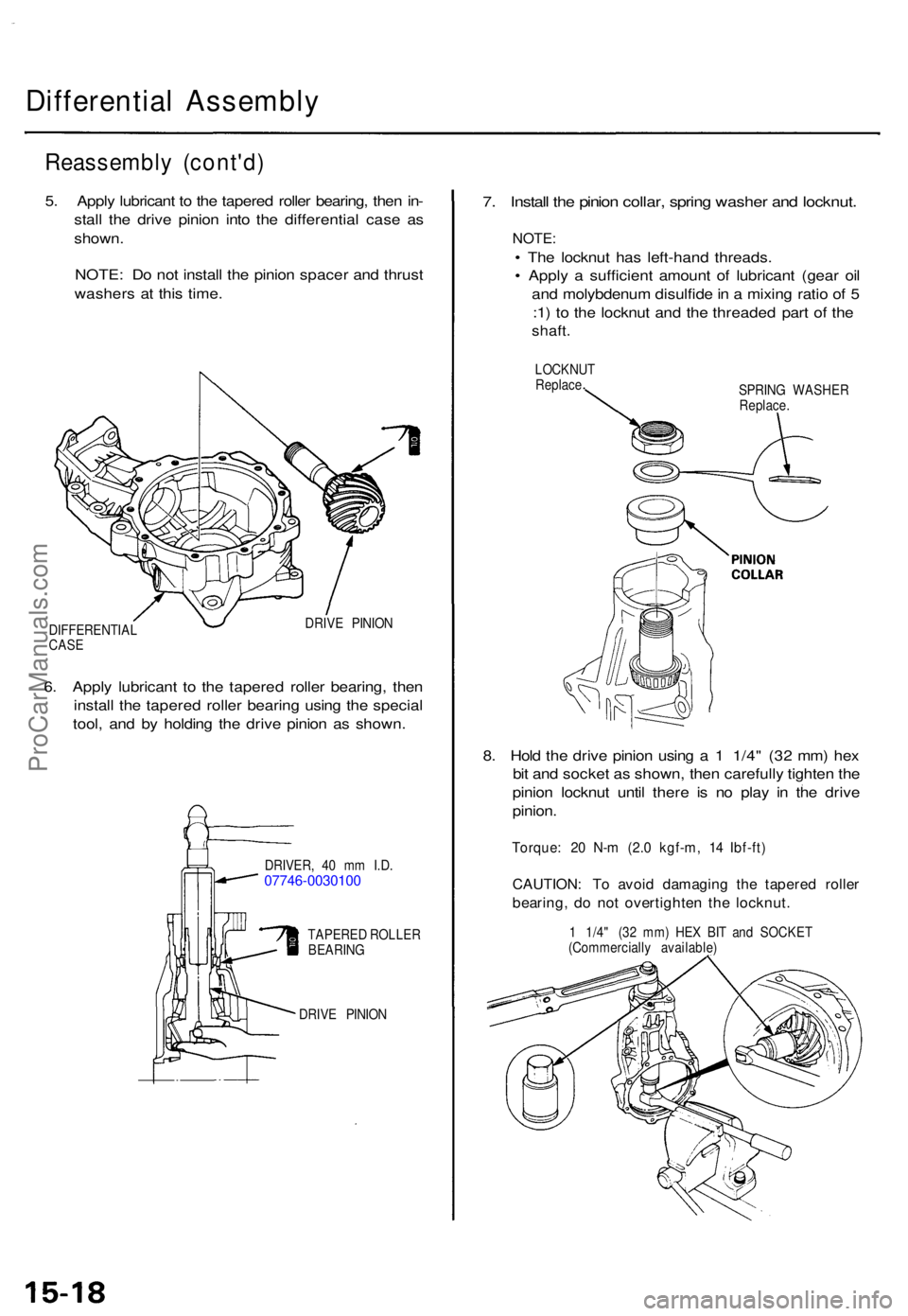
5. Appl y lubrican t t o th e tapere d rolle r bearing , the n in -
stal l th e driv e pinio n int o th e differentia l cas e a s
shown .
NOTE : D o no t instal l th e pinio n space r an d thrus t
washer s a t thi s time .
DIFFERENTIA L
CAS E DRIV
E PINIO N
6. Appl y lubrican t t o th e tapere d rolle r bearing , the n
instal l th e tapere d rolle r bearin g usin g th e specia l
tool , an d b y holdin g th e driv e pinio n a s shown .
DRIVER , 4 0 m m I.D .07746-0030100
TAPERE D ROLLE R
BEARIN G
DRIV E PINIO N
7. Instal l th e pinio n collar , sprin g washe r an d locknut .
NOTE:
• Th e locknu t ha s left-han d threads .
• Appl y a sufficien t amoun t o f lubrican t (gea r oi l
an d molybdenu m disulfid e in a mixin g rati o o f 5
: 1 ) t o th e locknu t an d th e threade d par t o f th e
shaft .
LOCKNU T
Replac e
SPRING WASHE R
Replace .
8. Hol d th e driv e pinio n usin g a 1 1/4 " (3 2 mm ) he x
bi t an d socke t a s shown , the n carefull y tighte n th e
pinio n locknu t unti l ther e i s n o pla y i n th e driv e
pinion .
Torque : 2 0 N- m (2. 0 kgf-m , 1 4 Ibf-ft )
CAUTION : T o avoi d damagin g th e tapere d rolle r
bearing , d o no t overtighte n th e locknut .
1 1/4 " (3 2 mm ) HE X BI T an d SOCKE T
(Commerciall y available )
ProCarManuals.com
Page 1113 of 1771
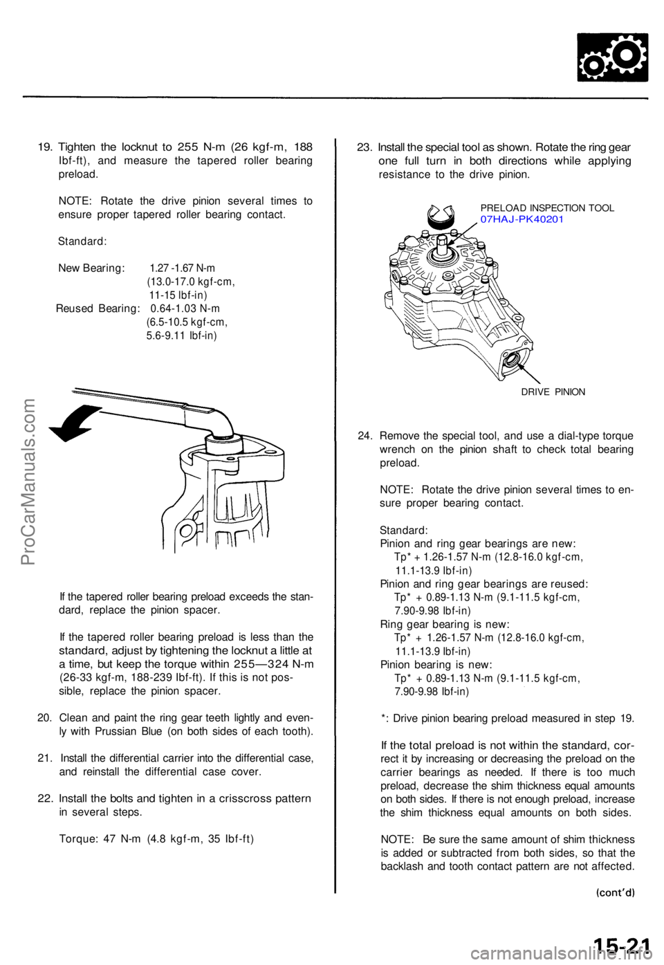
19. Tighte n th e locknu t t o 25 5 N- m (2 6 kgf-m , 18 8
Ibf-ft) , an d measur e th e tapere d rolle r bearin g
preload .
NOTE : Rotat e th e driv e pinio n severa l time s t o
ensur e prope r tapere d rolle r bearin g contact .
Standard :
New Bearing: 1.27 -1.67 N-m
(13.0-17.0 kgf-cm, 11-15 lbf-in)
Reuse d Bearing : 0.64-1.03 N-m
(6.5-10. 5 kgf-cm ,
5.6-9.1 1 Ibf-in )
If th e tapere d rolle r bearin g preloa d exceed s th e stan -
dard , replac e th e pinio n spacer .
I f th e tapere d rolle r bearin g preloa d i s les s tha n th e
standard , adjus t b y tightenin g th e locknu t a littl e a t
a time , bu t kee p th e torqu e withi n 255—32 4 N- m
(26-33 kgf-m, 188-239 Ibf-ft). If this is not pos-
sible , replac e th e pinio n spacer .
20 . Clea n an d pain t th e rin g gea r teet h lightl y an d even -
l y wit h Prussia n Blu e (o n bot h side s o f eac h tooth) .
21 . Instal l th e differentia l carrie r int o th e differentia l case ,
an d reinstal l th e differentia l cas e cover .
22. Instal l th e bolt s an d tighte n in a crisscros s patter n
in severa l steps.
Torque : 4 7 N- m (4. 8 kgf-m , 3 5 Ibf-ft )
23. Instal l th e specia l too l a s shown . Rotat e th e rin g gea r
one ful l tur n i n bot h direction s whil e applyin g
resistanc e t o th e driv e pinion .
PRELOA D INSPECTIO N TOO L07HAJ-PK40201
DRIVE PINIO N
24. Remov e th e specia l tool , an d us e a dial-typ e torqu e
wrenc h o n th e pinio n shaf t t o chec k tota l bearin g
preload .
NOTE: Rotat e th e driv e pinio n severa l time s t o en -
sur e prope r bearin g contact .
Standard :
Pinion an d rin g gea r bearing s ar e new :
Tp* + 1.26-1.57 N-m (12.8-16.0 kgf-cm,
11.1-13.9 Ibf-in)
Pinio n an d rin g gea r bearing s ar e reused :
Tp* + 0.89-1.1 3 N- m (9.1-11. 5 kgf-cm ,
7.90-9.9 8 Ibf-in )
Ring gea r bearin g is new :
Tp* + 1.26-1.5 7 N- m (12.8-16. 0 kgf-cm ,
11.1-13. 9 Ibf-in )
Pinion bearin g is new :
Tp* + 0.89-1.1 3 N- m (9.1-11. 5 kgf-cm ,
7.90-9.9 8 Ibf-in )
*: Driv e pinio n bearin g preloa d measure d in ste p 19 .
If th e tota l preloa d is no t withi n th e standard , cor -
rect i t b y increasin g o r decreasin g th e preloa d o n th e
carrie r bearing s a s needed . I f ther e i s to o muc h
preload , decreas e th e shi m thicknes s equa l amount s
o n bot h sides . I f ther e is no t enoug h preload , increas e
th e shi m thicknes s equa l amount s o n bot h sides .
NOTE : B e sur e th e sam e amoun t o f shi m thicknes s
i s adde d o r subtracte d fro m bot h sides , s o tha t th e
backlas h an d toot h contac t patter n ar e no t affected .
ProCarManuals.com
Page 1120 of 1771
Differential Assembl y
Installation (cont'd )
3. Instal l th e mountin g bolt s an d th e 2 6 m m shim .
Torque :12 x 1.2 5 mm64 N- m (6. 5 kgf-m , 4 7 Ibf-ft )
6 x 1. 0 m m12 N- m (1. 2 kgf-m ,8.7 Ibf-ft )
26 m m SHI M
4. Instal l th e vehicl e spee d senso r (VSS)/powe r steer -
in g spee d sensor , the n connec t th e oi l coole r hose s
an d th e breathe r tube .
VSS/POWE R STEERIN G
SPEE D SENSO R
VSS CONNECTO R
6 x 1. 0 m m12 N- m (1. 2 kgf-m ,8.7 Ibf-ft )
OILCOOLE RHOSES
BREATHE RTUBEO-RIN GReplace .
5. Instal l th e lef t fron t engin e moun t bracket .
12 x 1.2 5 mm74 N- m (7. 5 kgf-m ,54 Ibf-ft )
12 x 1.2 5 mm54 N- m (5. 5 kgf-m ,
4 0 Ibf-ft )
10 x 1.2 5 mm54 N- m (5. 5 kgf-m ,
4 0 Ibf-ft )
LEFT FRON T ENGIN E
MOUN T BRACKE T
6. Instal l th e splas h guard .
SPLAS HGUARD
6 x 1. 0 m m9.8 N- m (1. 0 kgf-m ,
7. 2 Ibf-ft )
ProCarManuals.com