1995 ACURA TL torque
[x] Cancel search: torquePage 1064 of 1771
Torque Converte r Housin g Bearing s
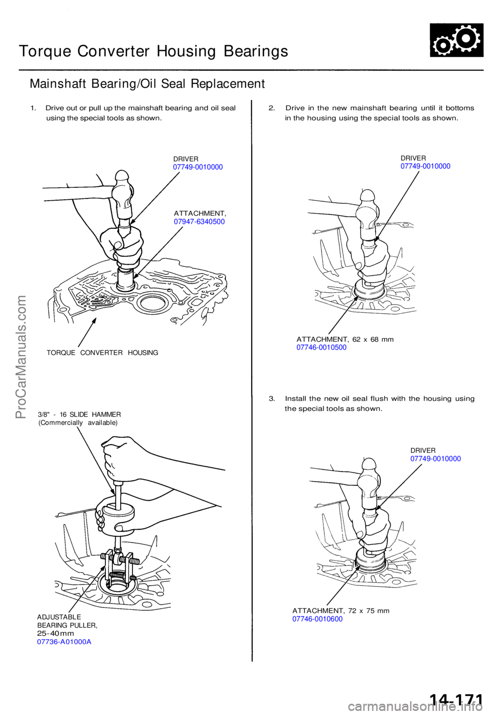
Mainshaf t Bearing/Oi l Sea l Replacemen t
1. Driv e ou t o r pul l u p th e mainshaf t bearin g an d oi l sea l
usin g th e specia l tool s a s shown .
DRIVER07749-001000 0
ATTACHMENT ,07947-6340500
TORQUE CONVERTE R HOUSIN G
3/8 " - 1 6 SLID E HAMME R
(Commerciall y available )
ADJUSTABL E
BEARIN G PULLER ,
25 - 4 0 m m07736-A01000 A
2. Driv e i n th e ne w mainshaf t bearin g unti l i t bottom s
i n th e housin g usin g th e specia l tool s a s shown .
DRIVER07749-001000 0
ATTACHMENT , 6 2 x 68 m m07746-001050 0
3. Instal l th e ne w oi l sea l flus h wit h th e housin g usin g
th e specia l tool s a s shown .
DRIVER07749-001000 0
ATTACHMENT , 7 2 x 7 5 m m07746-001060 0
ProCarManuals.com
Page 1065 of 1771
Torque Converte r Housin g
Bearing
Transmissio n Housin g
Bearing
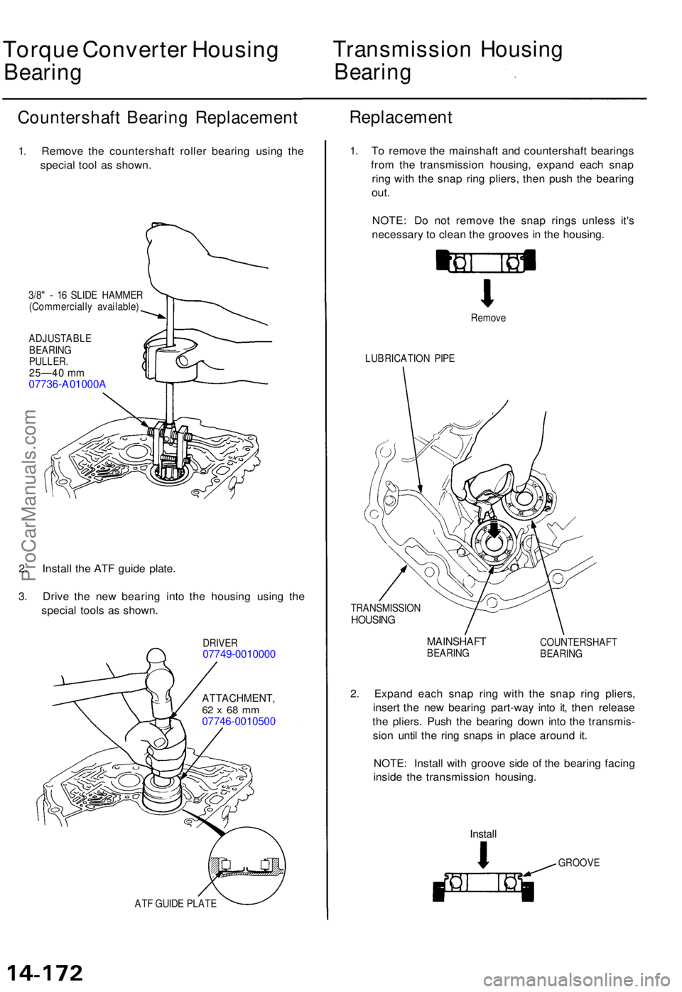
Countershaf t Bearin g Replacemen t
1. Remov e th e countershaf t rolle r bearin g usin g th e
specia l too l a s shown .
3/8" - 1 6 SLID E HAMME R
(Commerciall y available )
ADJUSTABL E
BEARIN G
PULLER .25—40 m m07736-A01000 A
2. Instal l th e AT F guid e plate .
3 . Driv e th e ne w bearin g int o th e housin g usin g th e
specia l tool s a s shown .
DRIVER07749-001000 0
ATTACHMENT ,62 x 68 m m07746-001050 0
Replacement
ATF GUID E PLAT E
1. T o remov e th e mainshaf t an d countershaf t bearing s
fro m th e transmissio n housing , expan d eac h sna p
rin g wit h th e sna p rin g pliers , the n pus h th e bearin g
out.
NOTE : D o no t remov e th e sna p ring s unles s it' s
necessar y t o clea n th e groove s i n th e housing .
Remove
LUBRICATIO N PIP E
TRANSMISSIO N
HOUSING
MAINSHAF TBEARING COUNTERSHAF
T
BEARIN G
2. Expan d eac h sna p rin g wit h th e sna p rin g pliers ,
inser t th e ne w bearin g part-wa y int o it , the n releas e
th e pliers . Pus h th e bearin g dow n int o th e transmis -
sio n unti l th e rin g snap s i n plac e aroun d it .
NOTE : Instal l wit h groov e sid e o f th e bearin g facin g
insid e th e transmissio n housing .
Install
GROOV E
ProCarManuals.com
Page 1070 of 1771
Transmission
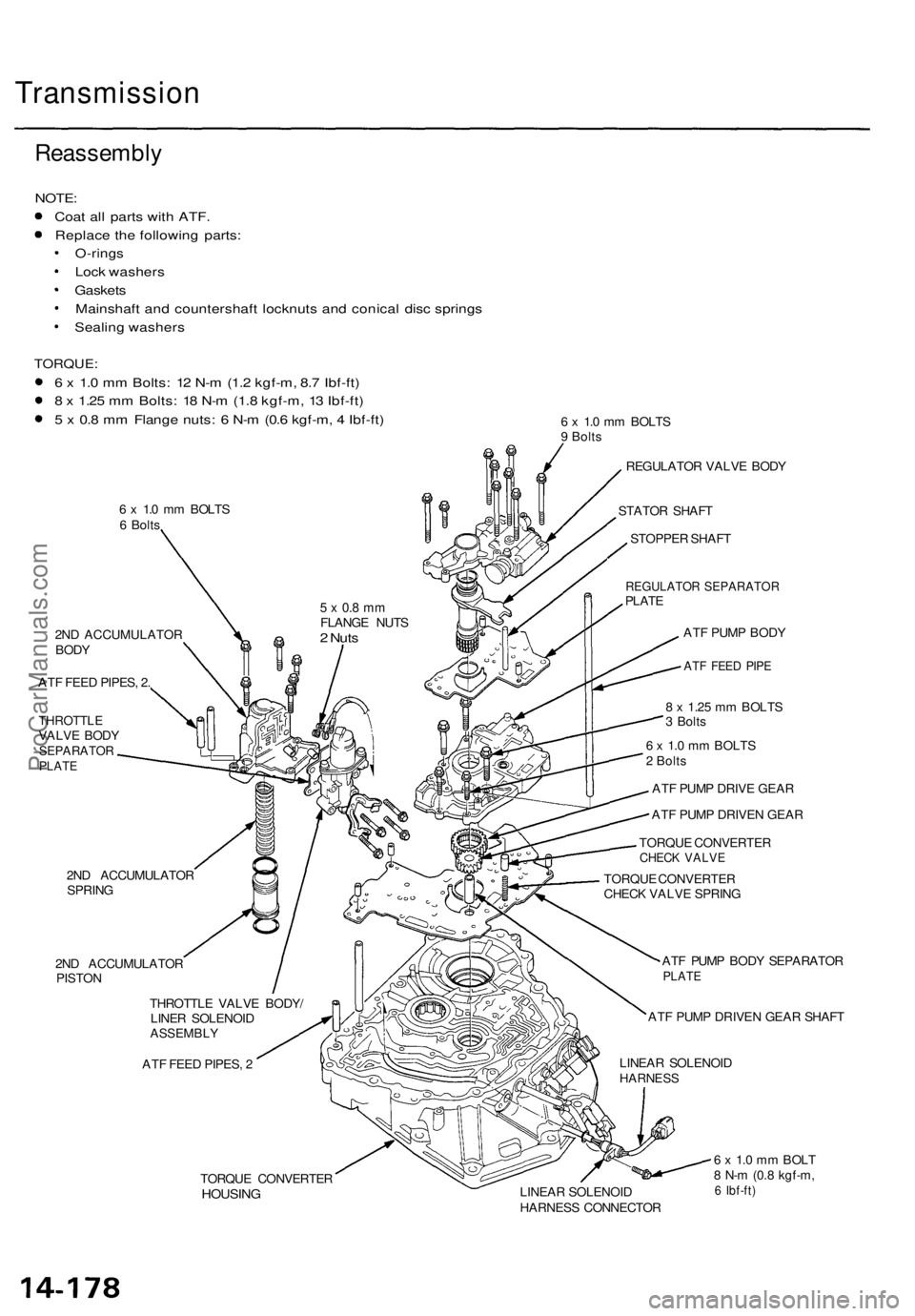
Reassembly
NOTE:
Coat all parts with ATF.
Replace the following parts:
O-rings
Lock washers
Gaskets
Mainshaft and countershaft locknuts and conical disc springs
Sealing washers
TORQUE:
6 x 1.0 mm Bolts: 12 N-m (1.2 kgf-m, 8.7 Ibf-ft)
8 x 1.25 mm Bolts: 18 N-m (1.8 kgf-m, 13 Ibf-ft)
5 x 0.8 mm Flange nuts: 6 N-m (0.6 kgf-m, 4 Ibf-ft)
6 x 1.0 mm BOLTS
6 Bolts
6 x 1.0 mm BOLTS
9 Bolts
2ND ACCUMULATOR
BODY
ATF FEED PIPES, 2.
THROTTLE
VALVE BODY
SEPARATOR
PLATE
2ND ACCUMULATOR
SPRING
2ND ACCUMULATOR
PISTON
THROTTLE VALVE BODY/
LINER SOLENOID
ASSEMBLY
ATF FEED PIPES, 2
REGULATOR VALVE BODY
STATOR SHAFT
STOPPER SHAFT
REGULATOR SEPARATOR
PLATE
ATF PUMP BODY
ATF FEED PIPE
8 x 1.25 mm BOLTS
3 Bolts
6 x 1.0 mm BOLTS
2 Bolts
ATF PUMP DRIVE GEAR
ATF PUMP DRIVEN GEAR
TORQUE CONVERTER
CHECK VALVE
TORQUE CONVERTER
CHECK VALVE SPRING
ATF PUMP BODY SEPARATOR
PLATE
ATF PUMP DRIVEN GEAR SHAFT
LINEAR SOLENOID
HARNESS
TORQUE CONVERTER
HOUSING
LINEAR SOLENOID
HARNESS CONNECTOR
6 x 1.0 mm BOLT
8 N-m (0.8 kgf-m,
6 Ibf-ft)
5 x 0.8 mm
FLANGE NUTS
2 NutsProCarManuals.com
Page 1071 of 1771
1. Install the linear solenoid harness and linear solenoid
harness connector into the torque converter housing.
2. Install the ATF pump body separator plate and three
dowel pins on the torque converter housing.
CAUTION: Take care not to pinch the linear solenoid
harness.
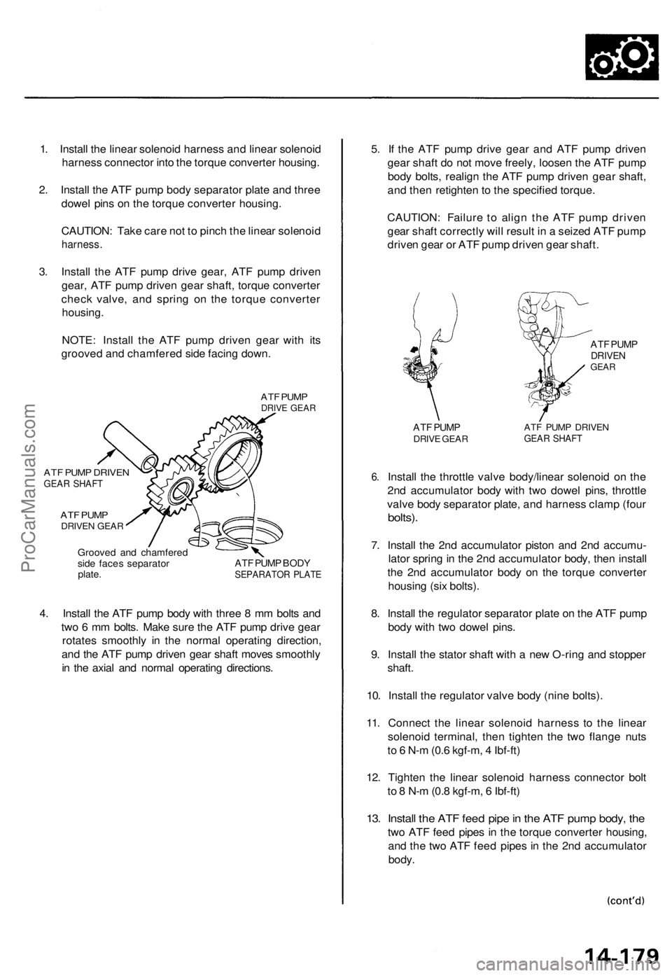
3. Install the ATF pump drive gear, ATF pump driven
gear, ATF pump driven gear shaft, torque converter
check valve, and spring on the torque converter
housing.
NOTE: Install the ATF pump driven gear with its
grooved and chamfered side facing down.
ATF PUMP
DRIVE GEAR
ATF PUMP DRIVEN
GEAR SHAFT
ATF PUMP
DRIVEN GEAR
Grooved and chamfered
side faces separator
plate.
ATF PUMP BODY
SEPARATOR PLATE
4. Install the ATF pump body with three 8 mm bolts and
two 6 mm bolts. Make sure the ATF pump drive gear
rotates smoothly in the normal operating direction,
and the ATF pump driven gear shaft moves smoothly
in the axial and normal operating directions.
5. If the ATF pump drive gear and ATF pump driven
gear shaft do not move freely, loosen the ATF pump
body bolts, realign the ATF pump driven gear shaft,
and then retighten to the specified torque.
CAUTION: Failure to align the ATF pump driven
gear shaft correctly will result in a seized ATF pump
driven gear or ATF pump driven gear shaft.
6.
ATF PUMP
DRIVEN
GEAR
ATF PUMP
DRIVE GEAR
ATF PUMP DRIVEN
GEAR SHAFT
Install the throttle valve body/linear solenoid on the
2nd accumulator body with two dowel pins, throttle
valve body separator plate, and harness clamp (four
bolts).
7. Install the 2nd accumulator piston and 2nd accumu-
lator spring in the 2nd accumulator body, then install
the 2nd accumulator body on the torque converter
housing (six bolts).
8. Install the regulator separator plate on the ATF pump
body with two dowel pins.
9. Install the stator shaft with a new O-ring and stopper
shaft.
10. Install the regulator valve body (nine bolts).
11. Connect the linear solenoid harness to the linear
solenoid terminal, then tighten the two flange nuts
to 6 N-m (0.6 kgf-m, 4 Ibf-ft)
12. Tighten the linear solenoid harness connector bolt
to 8 N-m (0.8 kgf-m, 6 Ibf-ft)
13. Install the ATF feed pipe in the ATF pump body, the
two ATF feed pipes in the torque converter housing,
and the two ATF feed pipes in the 2nd accumulator
body.ProCarManuals.com
Page 1072 of 1771
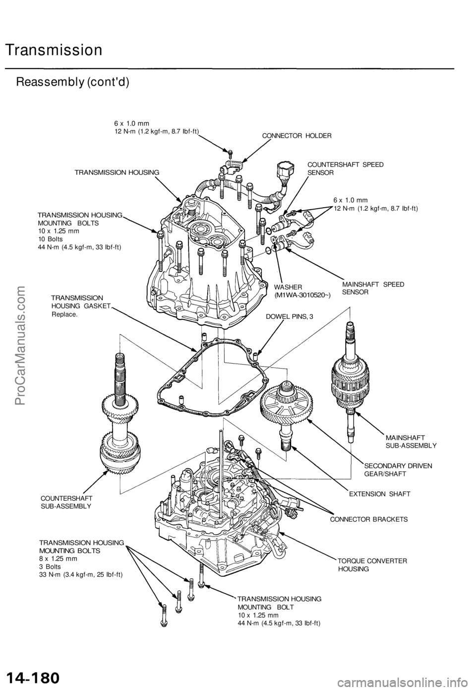
Transmission
Reassembly (cont'd)
6 x 1.0 mm
12 N-m (1.2 kgf-m, 8.7 Ibf-ft)
CONNECTOR HOLDER
TRANSMISSION HOUSING
TRANSMISSION HOUSING
MOUNTING BOLTS
10 x
1.25
mm
10 Bolts
44 N-m (4.5 kgf-m, 33 Ibf-ft)
TRANSMISSION
HOUSING GASKET.
Replace.
COUNTERSHAFT
SUB-ASSEMBLY
TRANSMISSION HOUSING
MOUNTING BOLTS
8 x
1.25
mm
3 Bolts
33 N-m (3.4 kgf-m, 25 Ibf-ft)
COUNTERSHAFT SPEED
SENSOR
6 x 1.0 mm
12 N-m (1.2 kgf-m, 8.7 Ibf-ft)
MAINSHAFT SPEED
SENSOR
MAINSHAFT
SUB-ASSEMBLY
SECONDARY DRIVEN
GEAR/SHAFT
EXTENSION SHAFT
CONNECTOR BRACKETS
TORQUE CONVERTER
HOUSING
TRANSMISSION HOUSING
MOUNTING BOLT
10 x
1.25
mm
44 N-m (4.5 kgf-m, 33 Ibf-ft)
DOWEL PINS, 3
WASHER
(M1WA-3010520~)ProCarManuals.com
Page 1075 of 1771
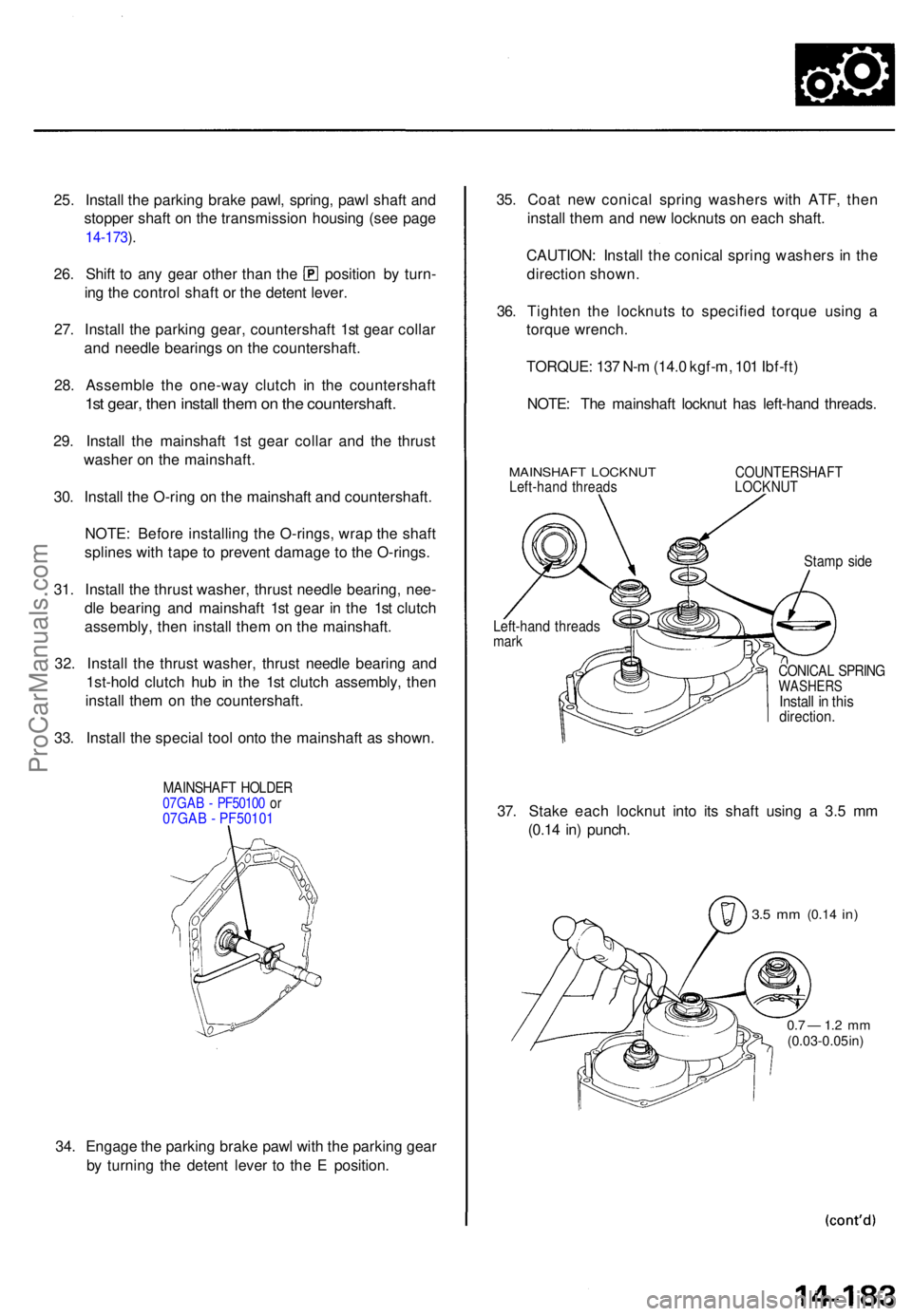
25. Instal l th e parkin g brak e pawl , spring , paw l shaf t an d
stoppe r shaf t o n th e transmissio n housin g (se e pag e
14-173 ).
26 . Shif t t o an y gea r othe r tha n th e positio n b y turn -
in g th e contro l shaf t o r th e deten t lever .
27 . Instal l th e parkin g gear , countershaf t 1s t gea r colla r
an d needl e bearing s o n th e countershaft .
28 . Assembl e th e one-wa y clutc h i n th e countershaf t
1st gear , the n instal l the m on th e countershaft .
29. Instal l th e mainshaf t 1s t gea r colla r an d th e thrus t
washe r o n th e mainshaft .
30 . Instal l th e O-rin g o n th e mainshaf t an d countershaft .
NOTE : Befor e installin g th e O-rings , wra p th e shaf t
spline s wit h tap e t o preven t damag e t o th e O-rings .
31 . Instal l th e thrus t washer , thrus t needl e bearing , nee -
dl e bearin g an d mainshaf t 1s t gea r i n th e 1s t clutc h
assembly , the n instal l the m o n th e mainshaft .
32 . Instal l th e thrus t washer , thrus t needl e bearin g an d
1st-hol d clutc h hu b i n th e 1s t clutc h assembly , the n
instal l the m o n th e countershaft .
33 . Instal l th e specia l too l ont o th e mainshaf t a s shown .
MAINSHAF T HOLDE R07GAB - PF5010 0 o r07GAB - PF50101
34 . Engag e th e parkin g brak e paw l wit h th e parkin g gea r
b y turnin g th e deten t leve r t o th e E position . 35
. Coa t ne w conica l sprin g washer s wit h ATF , the n
instal l the m an d ne w locknuts on eac h shaft .
CAUTION : Instal l th e conica l sprin g washer s in th e
directio n shown .
36 . Tighte n th e locknut s t o specifie d torqu e usin g a
torqu e wrench .
TORQUE : 13 7 N- m (14. 0 kgf-m , 10 1 Ibf-ft )
NOTE : Th e mainshaf t locknu t ha s left-han d threads .
MAINSHAF T LOCKNU TLeft-hand thread sCOUNTERSHAF TLOCKNUT
Stamp sid e
CONICA L SPRIN GWASHER SInstall i n thi sdirection .
37. Stak e eac h locknu t int o it s shaf t usin g a 3. 5 m m
(0.1 4 in ) punch .
3.5 m m (0.1 4 in)
0.7 — 1. 2 m m(0.03-0.0 5 in )
Left-han d thread smark
ProCarManuals.com
Page 1076 of 1771
Transmission
Reassembly (cont'd )
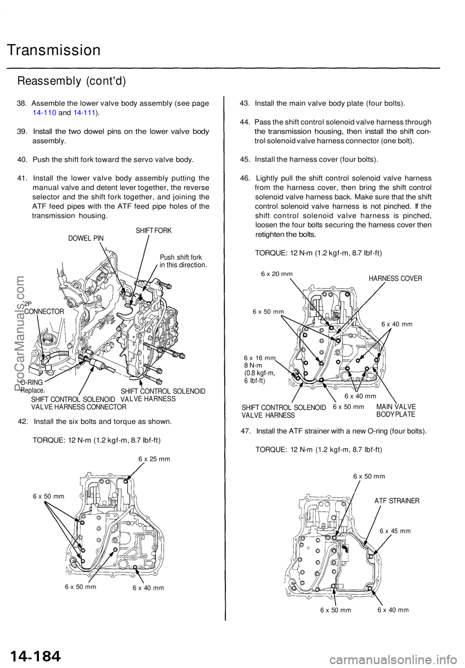
38. Assembl e th e lowe r valv e bod y assembl y (se e pag e
14-110 and 14-111 ).
39 . Instal l th e tw o dowe l pin s o n th e lowe r valv e bod y
assembly .
40. Pus h th e shif t for k towar d th e serv o valv e body .
41 . Instal l th e lowe r valv e bod y assembl y puttin g th e
manua l valv e an d deten t leve r together , th e revers e
selecto r an d th e shif t for k together , an d joinin g th e
AT F fee d pipe s wit h th e AT F fee d pip e hole s o f th e
transmissio n housing .
SHIFT FOR K
DOWE L PI N
Push shif t for k
in thi s direction .
2PCONNECTO R
6 x 50 m m
6 x 50 m m6 x 4 0 m m
43. Instal l th e mai n valv e bod y plat e (fou r bolts) .
44 . Pas s th e shif t contro l solenoi d valv e harnes s throug h
the transmissio n housing , the n instal l th e shif t con -
trol solenoi d valv e harnes s connecto r (on e bolt) .
45 . Instal l th e harnes s cove r (fou r bolts).
46 . Lightl y pul l th e shif t contro l solenoi d valv e harnes s
fro m th e harnes s cover , the n brin g th e shif t contro l
solenoi d valv e harnes s back . Mak e sur e tha t th e shif t
contro l solenoi d valv e harnes s i s no t pinched . I f th e
shif t contro l solenoi d valv e harnes s i s pinched ,
loose n th e fou r bolt s securin g th e harnes s cove r the n
retighte n th e bolts .
TORQUE : 1 2 N- m (1. 2 kgf-m , 8. 7 Ibf-ft )
6 x 20 m m
6 x 5 0 m m
HARNES S COVE R
6 x 4 0 m m
6 x 5 0 m m
6 x 4 5 m m
6 x 50 m m6 x 4 0 m m
42. Instal l th e si x bolt s an d torqu e a s shown .
TORQUE : 1 2 N- m (1. 2 kgf-m , 8. 7 Ibf-ft )
6 x 25 m m
SHIF T CONTRO L SOLENOI D
LVE HARNESS
SHIF T CONTRO L SOLENOI D VA
VALV E HARNES S CONNECTO R
O-RIN
GReplac e
6 x 1 6 m m8 N- m(0.8 kgf-m ,6 Ibf-ft )
6 x 4 0 m m
6 x 50 m mMAI N VALV E
BOD Y PLAT E
SHIF
T CONTRO L SOLENOI D
VALV E HARNES S
47. Instal l th e AT F straine r wit h a ne w O-rin g (fou r bolts) .
TORQUE : 1 2 N- m (1. 2 kgf-m , 8. 7 Ibf-ft )
ATF STRAINE R
ProCarManuals.com
Page 1077 of 1771
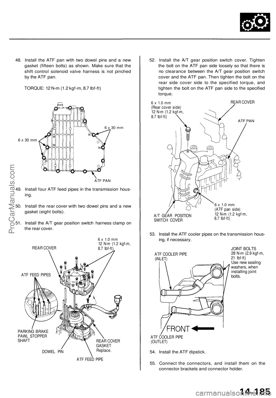
48. Install the ATF pan with two dowel pins and a new
gasket (fifteen bolts) as shown. Make sure that the
shift control solenoid valve harness is not pinched
by the ATF
pan.
TORQUE: 12 N-m (1.2 kgf-m, 8.7 Ibf-ft)
6 x 30 mm
6 x 30 mm
ATF PAN
49. Install four ATF feed pipes in the transmission hous-
ing.
50. Install the rear cover with two dowel pins and a new
gasket (eight bolts).
51. Install the A/T gear position switch harness clamp on
the rear cover.
REAR COVER
ATF FEED PIPES
6 x 1.0 mm
12 N-m (1.2 kgf-m,
8.7 Ibf-ft)
PARKING BRAKE
PAWL STOPPER
SHAFT
DOWEL PIN
REAR COVER
GASKET
Replace.
ATF FEED PIPE
52. Install the A/T gear position switch cover. Tighten
the bolt on the ATF pan side loosely so that there is
no clearance between the A/T gear position switch
cover and the ATF pan. Then tighten the bolt on the
rear side cover side to the specified torque, and
tighten the bolt on the ATF pan side to the specified
torque.
6 x 1.0 mm
(Rear cover side)
12 N-m (1.2 kgf-m,
8.7 Ibf-ft)
REAR COVER
ATF PAN
A/T GEAR POSITION
SWITCH COVER
6 x 1.0 mm
(ATF pan side)
12 N-m (1.2 kgf-m,
8.7 Ibf-ft)
53. Install the ATF cooler pipes on the transmission hous-
ing, if necessary.
ATF COOLER PIPE
(INLET)
JOINT BOLTS
28 N-m (2.9 kgf-m,
21 Ibf-ft)
Use new sealing
washers, when
installing joint
bolts.
ATF COOLER PIPE
(OUTLET)
54. Install the ATF dipstick.
55. Connect the connectors, and install them on the
connector brackets and connector holder.ProCarManuals.com