1995 ACURA TL torque
[x] Cancel search: torquePage 1137 of 1771
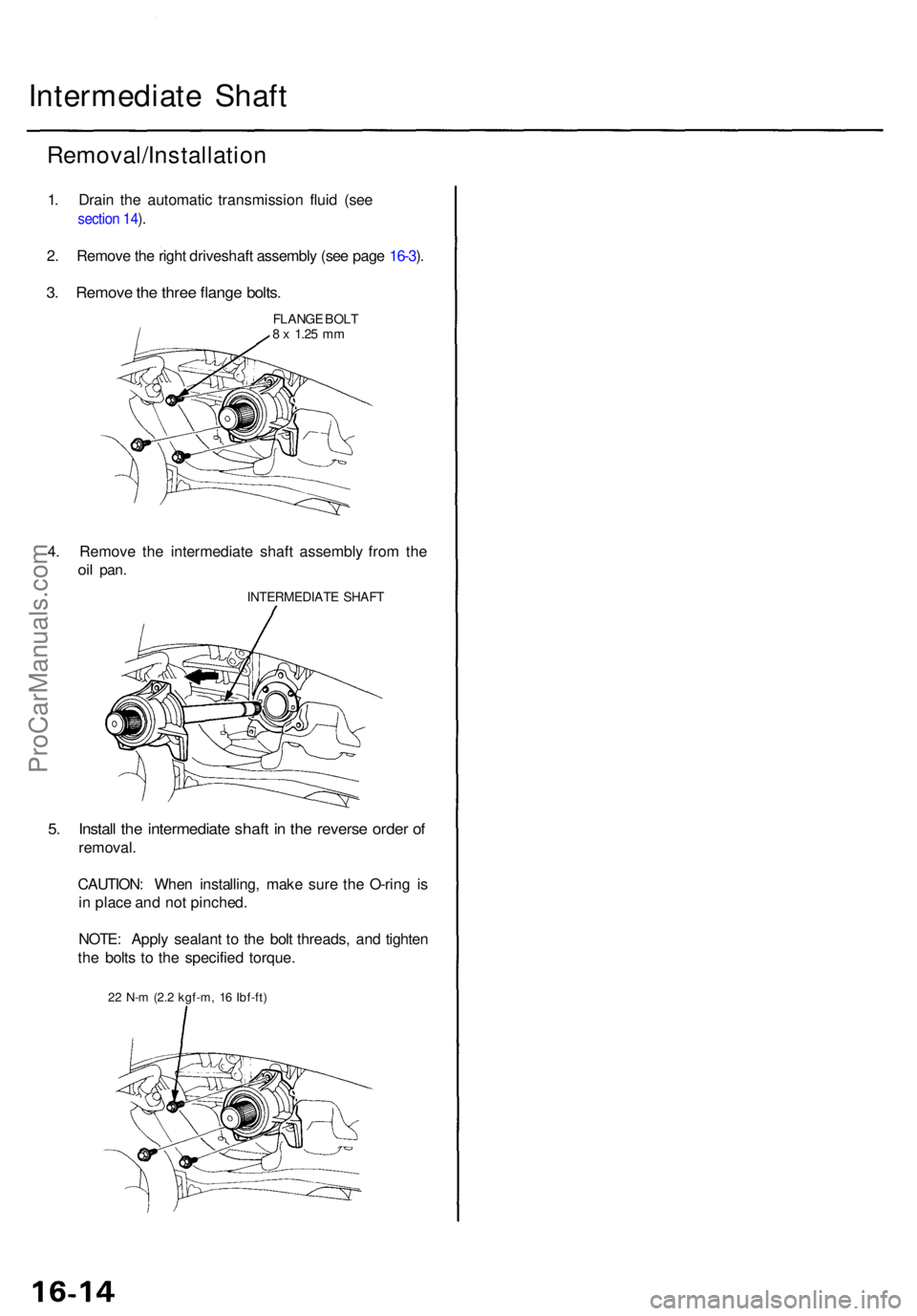
Intermediate Shaf t
Removal/Installatio n
1. Drai n th e automati c transmissio n flui d (se e
section 14 ).
2 . Remov e th e righ t driveshaf t assembl y (se e pag e 16-3 ).
3 . Remov e th e thre e flang e bolts .
FLANG E BOL T8 x 1.2 5 mm
4. Remov e th e intermediat e shaf t assembl y fro m th e
oil pan .
INTERMEDIAT E SHAF T
5. Instal l th e intermediat e shaf t i n th e revers e orde r o f
removal .
CAUTION : Whe n installing , mak e sur e th e O-rin g i s
i n plac e an d no t pinched .
NOTE : Appl y sealan t t o th e bol t threads , an d tighte n
th e bolt s t o th e specifie d torque .
22 N- m (2. 2 kgf-m , 1 6 Ibf-ft )
ProCarManuals.com
Page 1151 of 1771
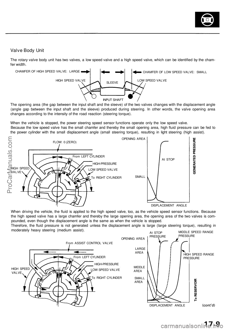
Valve Bod y Uni t
The rotar y valv e bod y uni t ha s tw o valves , a lo w spee d valv e an d a hig h spee d valve , whic h ca n b e identifie d b y th e cham -
fer width.
CHAMFE R O F HIG H SPEE D VALVE : LARG E
HIG H SPEE D VALV E
SLEEV E
CHAMFE R O F LO W SPEE D VALVE : SMAL L
LO W SPEE D VALV E
The openin g are a (th e ga p betwee n th e inpu t shaf t an d th e sleeve ) o f th e tw o valve s change s wit h th e displacemen t angl e
(angl e ga p betwee n th e inpu t shaf t an d th e sleeve ) produce d durin g steering . I n othe r words , th e valv e openin g are a
change s accordin g t o th e intensit y o f th e roa d reactio n (steerin g torque) .
Whe n th e vehicl e i s stopped , th e powe r steerin g spee d senso r function s operat e onl y th e lo w spee d valve .
Becaus e th e lo w spee d valv e ha s th e smal l chamfe r an d thereb y th e smal l openin g area , hig h flui d pressur e ca n b e fe d t o
th e powe r cylinde r wit h th e smal l displacemen t angl e (smal l steerin g torque) , resultin g i n ligh t steerin g (hig h assist) .
FLOW: 0 (ZERO ) OPENIN
G ARE A
HIG H SPEE D
VALV E
SMALL A
t STO P
DISPLACEMEN T ANGL E
When drivin g th e vehicle , th e flui d i s applie d t o th e hig h spee d valve , too , a s th e vehicl e spee d senso r functions . Becaus e
th e hig h spee d valv e ha s a larg e chamfe r an d thereb y th e larg e openin g area , th e openin g are a o f th e tw o valve s i s com -
pounded , eve n thoug h th e displacemen t angl e i s th e sam e a s whe n th e vehicl e i s stopped .
Therefore , th e flui d pressur e i s no t generate d unles s th e displacemen t angl e i s larg e (larg e steerin g torque) , resultin g i n
moderatel y heav y steerin g (mediu m assist) .
From ASSIS T CONTRO L VALV E
HIG H SPEE D
VALV E OPENIN
G ARE A
LARG EAREA
MIDDL EAREA
SMAL LAREA
At STO P
PRESSUR E MIDDL
E SPEE D RANG EPRESSUR E
DISPLACEMEN T ANGL E
T
o RIGH T CYLINDE R
LO
W SPEE D VALV E
HIGH-PRESSUR
E
Fro
m LEF T CYLINDE R HIG
H SPEE D RANG E
PRESSUR E
Fro
m LEF T CYLINDE R
HIGH-PRESSUR E
LO W SPEE D VALV E
T o RIGH T CYLINDE R
INPUT SHAF T
ProCarManuals.com
Page 1153 of 1771
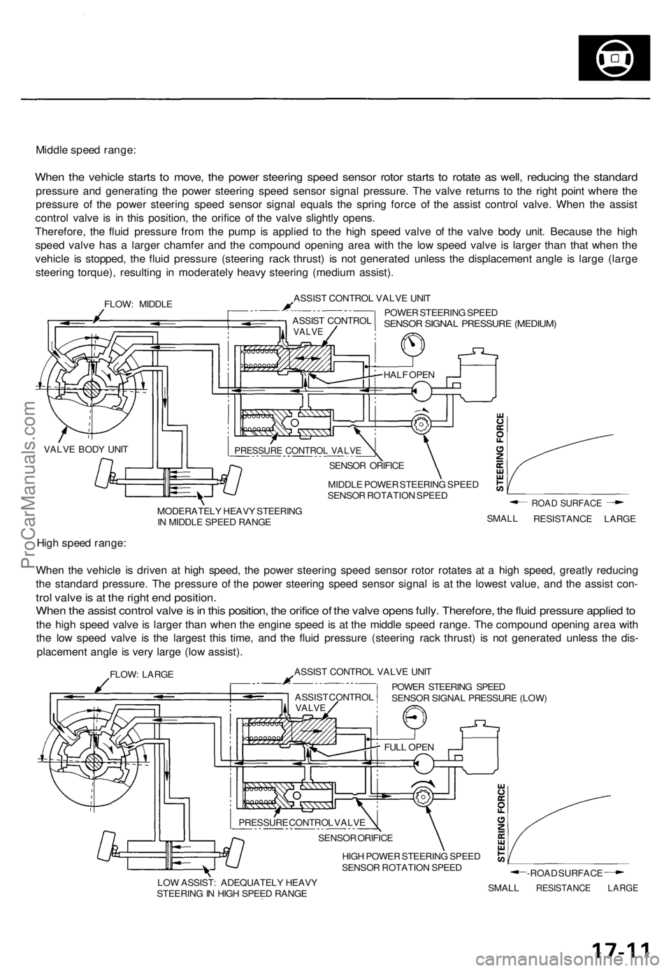
Middle speed range:
When the vehicle starts to move, the power steering speed sensor rotor starts to rotate as well, reducing the standard
pressure and generating the power steering speed sensor signal pressure. The valve returns to the right point where the
pressure of the power steering speed sensor signal equals the spring force of the assist control valve. When the assist
control valve is in this position, the orifice of the valve slightly opens.
Therefore, the fluid pressure from the pump is applied to the high speed valve of the valve body unit. Because the high
speed valve has a larger chamfer and the compound opening area with the low speed valve is larger than that when the
vehicle is stopped, the fluid pressure (steering rack thrust) is not generated unless the displacement angle is large (large
steering torque), resulting in moderately heavy steering (medium assist).
FLOW: MIDDLE
ASSIST CONTROL VALVE UNIT
POWER STEERING SPEED
SENSOR SIGNAL PRESSURE (MEDIUM)
MIDDLE POWER STEERING SPEED
SENSOR ROTATION SPEED
MODERATELY HEAVY STEERING
IN MIDDLE SPEED RANGE
SMALL
ROAD SURFACE
RESISTANCE LARGE
High speed range:
When the vehicle is driven at high speed, the power steering speed sensor rotor rotates at a high speed, greatly reducing
the standard pressure. The pressure of the power steering speed sensor signal is at the lowest value, and the assist con-
trol valve is at the right end position.
When the assist control valve is in this position, the orifice of the valve opens fully. Therefore, the fluid pressure applied to
the high speed valve is larger than when the engine speed is at the middle speed range. The compound opening area with
the low speed valve is the largest this time, and the fluid pressure (steering rack thrust) is not generated unless the dis-
placement angle is very large (low assist).
FLOW: LARGE
ASSIST CONTROL VALVE UNIT
POWER STEERING SPEED
SENSOR SIGNAL PRESSURE (LOW)
HIGH POWER STEERING SPEED
SENSOR ROTATION SPEED
LOW ASSIST: ADEQUATELY HEAVY
STEERING IN HIGH SPEED RANGE
SMALL
-ROAD SURFACE
RESISTANCE LARGE
PRESSURE CONTROL VALVE
SENSOR ORIFICE
HALF OPEN
ASSIST CONTROL
VALVE
VALVE BODY UNIT
ASSIST CONTROL
VALVE
FULL OPEN
SENSOR ORIFICE
PRESSURE CONTROL VALVEProCarManuals.com
Page 1155 of 1771
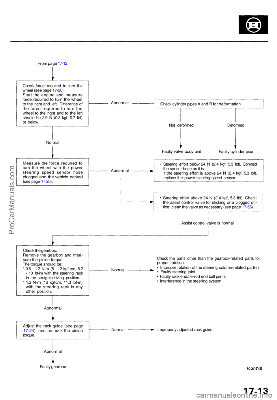
From pag e 17-1 2
Chec k forc e require d t o tur n th e
whee l (se e pag e 17-20 ).
Star t th e engin e an d measur e
force require d t o tur n th e whee lto th e righ t an d left . Differenc e o fth e forc e require d t o tur n th ewhee l t o th e righ t an d t o th e lef tshoul d b e 2. 9 N (0. 3 kgf , 0. 7 Ibf )
o r below . Abnorma
l
Check cylinde r pipe s A an d B fo r deformation .
Norma l No
t deforme d
Faulty valv e bod y uni t
Deforme d
Faulty cylinde r pip e
Measur e th e forc e require d t o
tur n th e whee l wit h th e powe r
steerin g spee d senso r hos e
plugge d an d th e vehicl e parke d(see pag e 17-20 ).
Abnorma l
Steering effor t belo w 2 4 N (2. 4 kgf , 5. 3 Ibf) . Connec t
th e senso r hos e a s it is .
I f th e steerin g effor t i s abov e 2 4 N (2. 4 kgf , 5. 3 Ibf) ,
replac e th e powe r steerin g spee d sensor .
Steerin g effor t abov e 2 4 N (2. 4 kgf , 5. 3 Ibf) . Chec k
th e assis t contro l valv e fo r stickin g o r a clogge d ori -
fice ; clea n th e valv e a s necessar y (se e pag e 17-55 ).
Assis t contro l valv e is norma l
Chec k th e gearbox .
Remov e th e gearbo x an d mea -
sur e th e pinio n torque .
Th e torqu e shoul d be ;
* 0. 6 - 1. 2 N- m (6 - 1 2 kgf-cm , 5. 2
- 1 0 Ibf-in ) wit h th e steerin g rac k
i n th e straigh t drivin g position .
* 1. 3 N- m (1 3 kgf-cm , 11. 3 Ibf-in )with th e steerin g rac k i n an y
othe r position .
Normal
Check th e part s othe r tha n th e gearbox-relate d part s fo r
prope r rotation .
• Imprope r rotatio n o f th e steerin g column-relate d part(s )
• Fault y steerin g join t
• Fault y rac k end/tie-ro d en d bal l joint s
• Interferenc e in th e steerin g syste m
Abnorma l
Adjus t th e rac k guid e (se e pag e
17-24 ), an d rechec k th e pinio n
torque.
Norma l Improperl y adjuste d rac k guid e
Abnorma l
Faulty gearbo x
ProCarManuals.com
Page 1207 of 1771
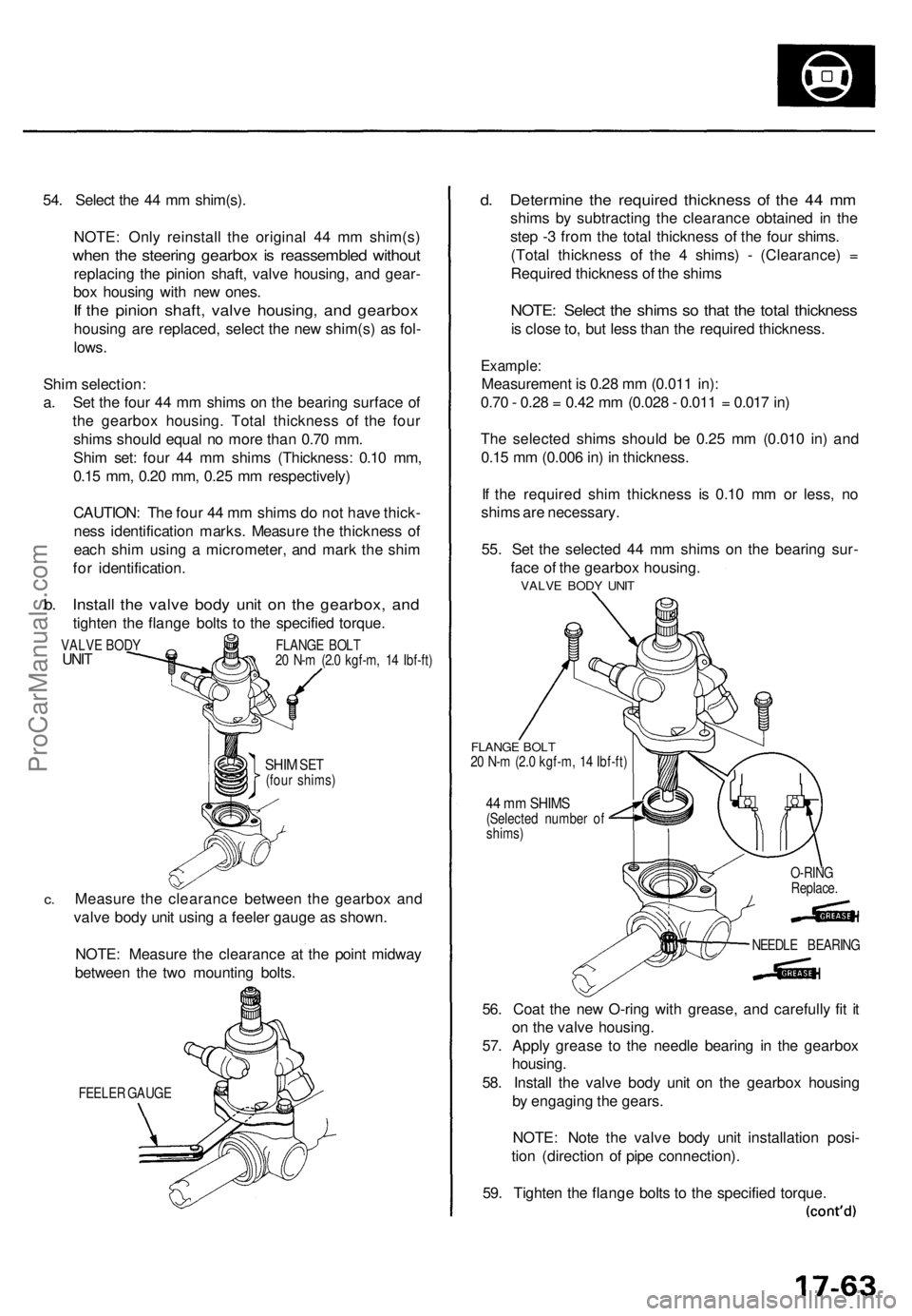
54. Selec t th e 4 4 m m shim(s) .
NOTE : Onl y reinstal l th e origina l 4 4 m m shim(s )
when th e steerin g gearbo x i s reassemble d withou t
replacin g th e pinio n shaft , valv e housing , an d gear -
bo x housin g wit h ne w ones .
If th e pinio n shaft , valv e housing , an d gearbo x
housing ar e replaced , selec t th e ne w shim(s ) a s fol -
lows .
Shi m selection :
a . Se t th e fou r 4 4 m m shim s o n th e bearin g surfac e o f
th e gearbo x housing . Tota l thicknes s o f th e fou r
shim s shoul d equa l n o mor e tha n 0.7 0 mm .
Shi m set : fou r 4 4 m m shim s (Thickness : 0.1 0 mm ,
0.1 5 mm , 0.2 0 mm , 0.2 5 m m respectively )
CAUTION : Th e fou r 4 4 m m shim s d o no t hav e thick -
nes s identificatio n marks . Measur e th e thicknes s o f
eac h shi m usin g a micrometer , an d mar k th e shi m
fo r identification .
b. Instal l th e valv e bod y uni t o n th e gearbox , an d
tighte n th e flang e bolt s t o th e specifie d torque .
SHIM SET(fou r shims )
c.Measur e th e clearanc e betwee n th e gearbo x an d
valv e bod y uni t usin g a feele r gaug e a s shown .
NOTE : Measur e th e clearanc e a t th e poin t midwa y
betwee n th e tw o mountin g bolts .
FEELE R GAUG E
d. Determin e th e require d thicknes s o f th e 4 4 m m
shim s b y subtractin g th e clearanc e obtaine d i n th e
ste p - 3 fro m th e tota l thicknes s o f th e fou r shims .
(Tota l thicknes s o f th e 4 shims ) - (Clearance ) =
Require d thicknes s o f th e shim s
NOTE : Selec t th e shim s s o tha t th e tota l thicknes s
is clos e to , bu t les s tha n th e require d thickness .
Example:
Measuremen t i s 0.2 8 m m (0.01 1 in) :
0.7 0 - 0.2 8 = 0.4 2 m m (0.02 8 - 0.01 1 = 0.01 7 in )
Th e selecte d shim s shoul d b e 0.2 5 m m (0.01 0 in ) an d
0.1 5 m m (0.00 6 in ) i n thickness .
I f th e require d shi m thicknes s i s 0.1 0 m m o r less , n o
shim s ar e necessary .
55 . Se t th e selecte d 4 4 m m shim s o n th e bearin g sur -
fac e o f th e gearbo x housing .
FLANGE BOL T20 N- m (2. 0 kgf-m , 1 4 Ibf-ft )
44 m m SHIM S(Selecte d numbe r o f
shims )
56. Coa t th e ne w O-rin g wit h grease , an d carefull y fi t i t
o n th e valv e housing .
57 . Appl y greas e t o th e needl e bearin g i n th e gearbo x
housing .
58 . Instal l th e valv e bod y uni t o n th e gearbo x housin g
b y engagin g th e gears .
NOTE : Not e th e valv e bod y uni t installatio n posi -
tio n (directio n o f pip e connection) .
59 . Tighte n th e flang e bolt s t o th e specifie d torque .
VALVE BOD YUNITFLANG E BOL T
2 0 N- m (2. 0 kgf-m , 1 4 Ibf-ft )
NEEDLE BEARIN G
O-RIN
G
Replace .
VALVE BOD Y UNI T
ProCarManuals.com
Page 1208 of 1771
Steering Gearbo x
Reassembl y (cont'd )
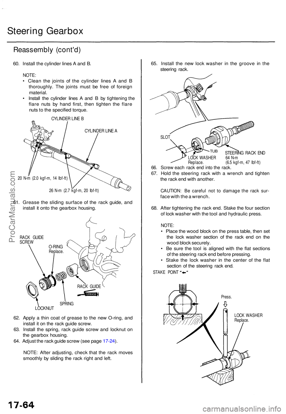
60. Instal l th e cylinde r line s A an d B .
NOTE :
• Clea n th e joint s o f th e cylinde r line s A an d B
thoroughly . Th e joint s mus t b e fre e o f foreig n
material .
• Instal l th e cylinde r line s A an d B by
tightening the
flar e nut s b y han d first , the n tighte n th e flar e
nut s t o th e specifie d torque .
CYLINDE R LIN E B
CYLINDE R LIN E A
20 N- m (2. 0 kgf-m , 1 4 Ibf-ft )
2 6 N- m (2. 7 kgf-m , 2 0 Ibf-ft )
61. Greas e th e slidin g surfac e o f th e rac k guide , an d
instal l i t ont o th e gearbo x housing .
RACK GUID E
SCRE W
SPRING
LOCKNU T
62. Appl y a thi n coa t o f greas e t o th e ne w O-ring , an d
instal l i t o n th e rac k guid e screw .
63 . Instal l th e spring , rac k guid e scre w an d locknu t o n
th e gearbo x housing .
64 . Adjus t th e rac k guid e scre w (se e pag e 17-24 ).
NOTE : Afte r adjusting , chec k tha t th e rac k move s
smoothl y b y slidin g th e rac k righ t an d left . 65
. Instal l th e ne w loc k washe r i n th e groov e i n th e
steerin g rack .
STEERIN G RAC K EN DLOC K WASHE R 6 4 N- m
Replace . (6. 5 kgf-m , 4 7 Ibf-ft )
66. Scre w eac h rac k en d int o th e rack .
67. Hol d th e steerin g rac k wit h a wrenc h an d tighte n
th e rac k en d wit h another .
CAUTION : B e carefu l no t t o damag e th e rac k sur -
face wit h th e a wrench .
68 . Afte r tightenin g th e rac k end . Stak e th e fou r sectio n
o f loc k washe r wit h th e too l an d hydrauli c press .
NOTE:
• Plac e th e woo d bloc k o n th e pres s table , the n se t
th e loc k washe r sectio n o f th e rac k en d o n th e
woo d bloc k securely .
• B e sur e th e too l i s aligne d wit h th e fla t section s
o f th e steerin g rac k en d befor e pressing .
• Stak e th e loc k washe r i n th e cente r o f th e fla t
sectio n o f th e steerin g rac k end .
Press .
LOC K WASHE R
Replace .
RAC
K GUID E
O-RINGReplace .
TUB
SLO T
STAK E POIN T
ProCarManuals.com
Page 1213 of 1771
Steering Gearbo x
Installatio n (cont'd )
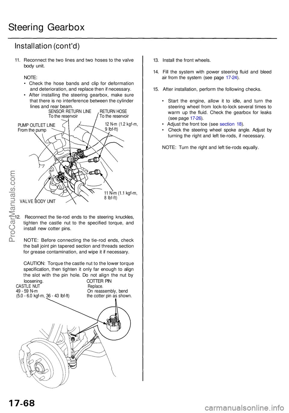
11. Reconnec t th e tw o line s an d tw o hose s t o th e valv e
body unit .
NOTE :
• Chec k th e hos e band s an d cli p fo r deformatio n
an d deterioration , an d replac e the n if necessary .
• Afte r installin g th e steerin g gearbox , mak e sur e
tha t ther e is n o interferenc e betwee n th e cylinde r
line s an d rea r beam .
PUMP OUTLE T LIN EFrom th e pum p
12 N- m (1. 2 kgf-m ,9 Ibf-ft )
VALV E BOD Y UNI T
11 N- m (1. 1 kgf-m ,8 Ibf-ft )
12. Reconnec t th e tie-ro d end s t o th e steerin g knuckles ,
tighte n th e castl e nu t t o th e specifie d torque , an d
instal l ne w cotte r pins .
NOTE : Befor e connectin g th e tie-ro d ends , chec k
th e bal l join t pi n tapere d sectio n an d thread s sectio n
fo r greas e contamination , an d wip e it i f necessary .
CAUTION : Torqu e th e castl e nu t t o th e lowe r torqu e
specification , the n tighte n it onl y fa r enoug h t o alig n
th e slo t wit h th e pi n hole . D o no t alig n th e nu t b y
loosening . COTTER PI NCASTL E NU T Replace.49 - 5 9 N- m O n reassembly , ben d(5.0 - 6. 0 kgf-m , 3 6 - 4 3 Ibf-ft ) th e cotte r pi n a s shown .
13. Instal l th e fron t wheels .
14 . Fil l th e syste m wit h powe r steerin g flui d an d blee d
ai r fro m th e syste m (se e pag e 17-24 ).
15 . Afte r installation , perfor m th e followin g checks .
• Star t th e engine , allo w i t t o idle , an d tur n th e
steerin g whee l fro m lock-to-loc k severa l time s t o
war m u p th e fluid . Chec k th e gearbo x fo r leak s
(se e pag e 17-26 ).
• Adjus t th e fron t to e (se e sectio n 18 ).
• Chec k th e steerin g whee l spok e angle . Adjus t b y
turnin g th e righ t an d lef t tie-rods , i f necessary .
NOTE : Tur n th e righ t an d lef t tie-rod s equally .
SENSO R RETUR N LIN ETo th e reservoi rRETURN HOS ETo th e reservoi r
ProCarManuals.com
Page 1218 of 1771
Wheel Alignmen t
Caster
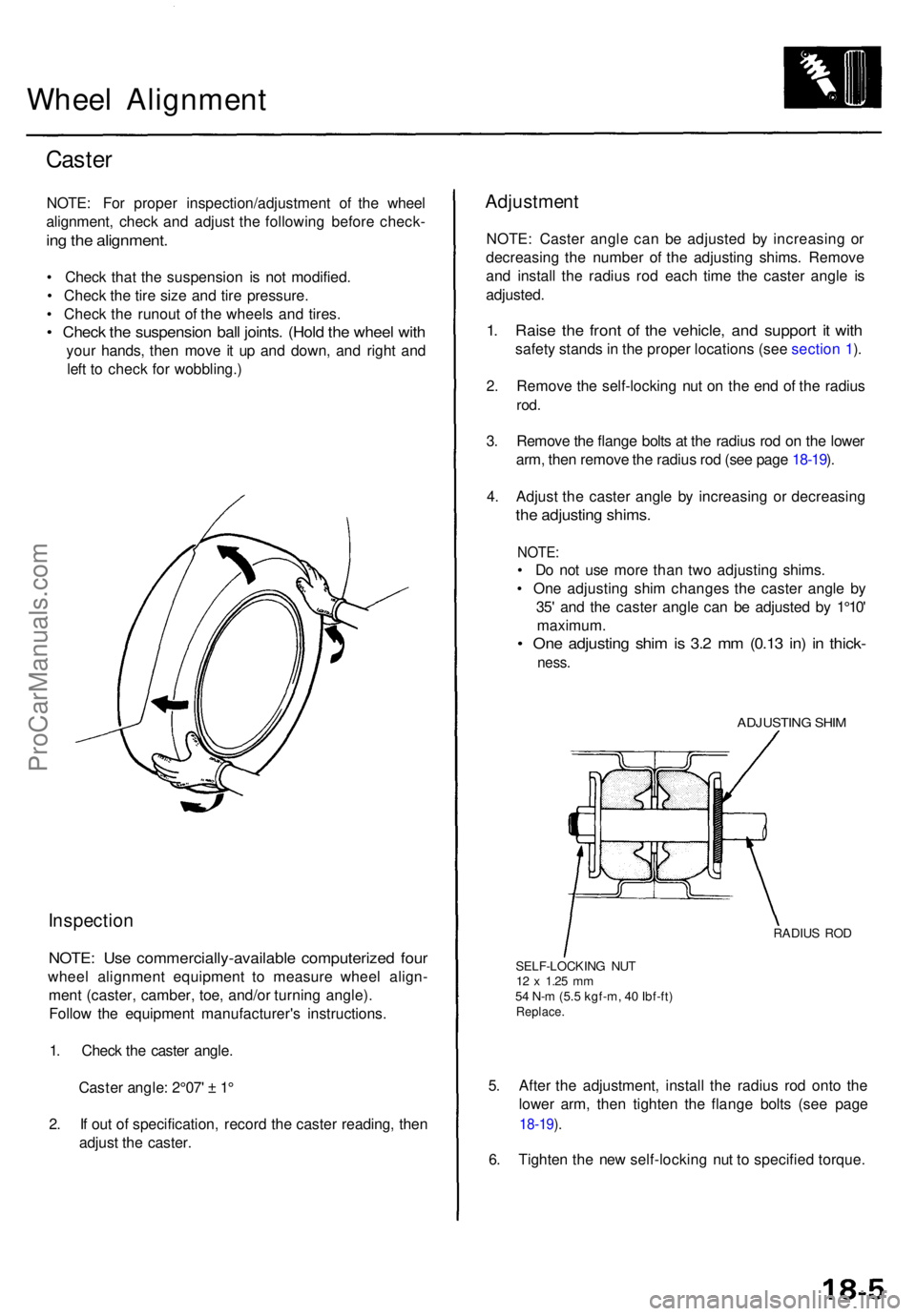
NOTE : Fo r prope r inspection/adjustmen t o f th e whee l
alignment , chec k an d adjus t th e followin g befor e check -
ing th e alignment .
• Chec k tha t th e suspensio n i s no t modified .
• Chec k th e tir e siz e an d tir e pressure .
• Chec k th e runou t o f th e wheel s an d tires .
• Chec k th e suspensio n bal l joints . (Hol d th e whee l wit h
you r hands , the n mov e i t u p an d down , an d righ t an d
lef t t o chec k fo r wobbling. )
Inspection
NOTE: Us e commercially-availabl e computerize d fou r
whee l alignmen t equipmen t t o measur e whee l align -
men t (caster , camber , toe , and/o r turnin g angle) .
Follo w th e equipmen t manufacturer' s instructions .
1 . Chec k th e caste r angle .
Caste r angle : 2°07 ' ± 1 °
2 . I f ou t o f specification , recor d th e caste r reading , the n
adjus t th e caster .
Adjustmen t
NOTE: Caste r angl e ca n b e adjuste d b y increasin g o r
decreasin g th e numbe r o f th e adjustin g shims . Remov e
an d instal l th e radiu s ro d eac h tim e th e caste r angl e i s
adjusted .
1. Rais e th e fron t o f th e vehicle , an d suppor t i t wit h
safet y stand s in th e prope r location s (se e sectio n 1 ).
2 . Remov e th e self-lockin g nu t o n th e en d o f th e radiu s
rod.
3. Remov e th e flang e bolt s a t th e radiu s ro d o n th e lowe r
arm , the n remov e th e radiu s ro d (se e pag e 18-19 ).
4 . Adjus t th e caste r angl e b y increasin g o r decreasin g
the adjustin g shims .
NOTE:
• D o no t us e mor e tha n tw o adjustin g shims .
• On e adjustin g shi m change s th e caste r angl e b y
35 ' an d th e caste r angl e ca n b e adjuste d b y 1°10 '
maximum .
• On e adjustin g shi m is 3. 2 m m (0.1 3 in ) i n thick -
ness.
ADJUSTIN G SHI M
RADIU S RO D
SELF-LOCKIN G NU T
12 x 1.2 5 mm54 N- m (5. 5 kgf-m , 4 0 Ibf-ft )Replace .
5. Afte r th e adjustment , instal l th e radiu s ro d ont o th e
lowe r arm , the n tighte n th e flang e bolt s (se e pag e
18-19 ).
6 . Tighte n th e ne w self-lockin g nu t t o specifie d torque .
ProCarManuals.com