1995 ACURA TL torque
[x] Cancel search: torquePage 1222 of 1771
Front Suspension
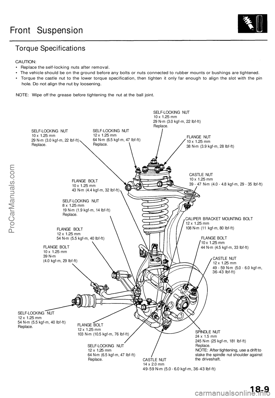
Torque Specifications
CAUTION:
• Replace the self-locking nuts after removal.
• The vehicle should be on the ground before any bolts or nuts connected to rubber mounts or bushings are tightened.
• Torque the castle nut to the lower torque specification, then tighten it only far enough to align the slot with the pin
hole. Do not align the nut by loosening.
NOTE: Wipe off the grease before tightening the nut at the ball joint.
SELF-LOCKING NUT
10 x
1.25
mm
29 N-m (3.0 kgf-m, 22 Ibf-ft)
Replace.
SELF-LOCKING NUT
12 x
1.25
mm
64 N-m (6.5 kgf-m, 47 Ibf-ft)
Replace.
SELF-LOCKING NUT
10 x
1.25
mm
29 N-m (3.0 kgf-m, 22 Ibf-ft)
Replace.
FLANGE BOLT
10 x
1.25
mm
43 N-m (4.4 kgf-m, 32 Ibf-ft)
SELF-LOCKING NUT
8 x
1.25
mm
19 N-m (1.9 kgf-m, 14 Ibf-ft)
Replace.
FLANGE BOLT
12 x
1.25
mm
54 N-m (5.5 kgf-m, 40 Ibf-ft)
FLANGE BOLT
10 x
1.25
mm
39 N-m
(4.0 kgf-m, 29 Ibf-ft)
SELF-LOCKING NUT
12 x
1.25
mm
54 N-m (5.5 kgf-m, 40 Ibf-ft)
Replace.
FLANGE NUT
10 x
1.25
mm
38 N-m (3.9 kgf-m, 28 Ibf-ft)
CASTLE NUT
10 x
1.25
mm
39 - 47 N-m (4.0 - 4.8 kgf-m, 29 - 35 Ibf-ft)
CALIPER BRACKET MOUNTING BOLT
12 x
1.25
mm
108 N-m (11 kgf-m, 80 Ibf-ft)
FLANGE BOLT
10 x
1.25
mm
44 N-m (4.5 kgf-m, 33 Ibf-ft)
CASTLE NUT
12 x
1.25
mm
49 - 59 N-m (5.0 - 6.0 kgf-m,
36-43 Ibf-ft)
FLANGE BOLT
12 x
1.25
mm
103 N-m (10.5 kgf-m, 76 Ibf-ft)
SELF-LOCKING NUT
12 x
1.25
mm
64 N-m (6.5 kgf-m, 47 Ibf-ft)
Replace.
CASTLE NUT
14 x 2.0 mm
49-59 N-m (5.0 - 6.0 kgf-m, 36-43 Ibf-ft)
SPINDLE NUT
24 x 1.5 mm
245 N-m (25 kgf-m, 181 Ibf-ft)
Replace.
NOTE: After tightening, use a drift to
stake the spindle nut shoulder against
the driveshaft.ProCarManuals.com
Page 1236 of 1771
Installation
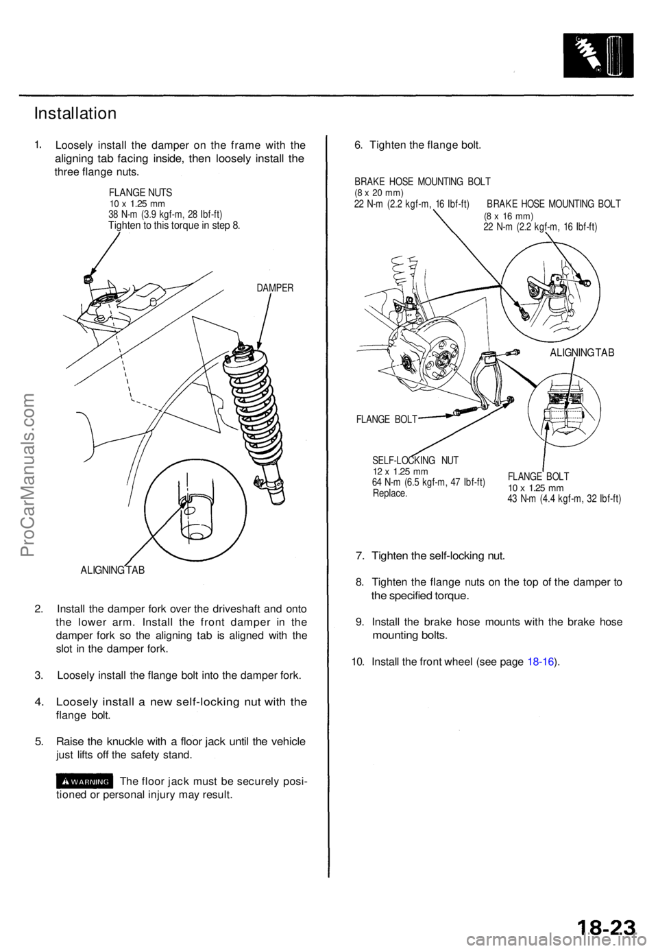
1. Loosel y instal l th e dampe r o n th e fram e wit h th e
alignin g ta b facin g inside , the n loosel y instal l th e
thre e flang e nuts .
FLANG E NUT S10 x 1.2 5 mm38 N- m (3. 9 kgf-m , 2 8 Ibf-ft )Tighte n to thi s torqu e in ste p 8 .
DAMPE R
ALIGNIN G TA B
2. Instal l th e dampe r for k ove r th e driveshaf t an d ont o
th e lowe r arm . Instal l th e fron t dampe r i n th e
dampe r for k s o th e alignin g ta b i s aligne d wit h th e
slo t i n th e dampe r fork .
3 . Loosel y instal l th e flang e bol t int o th e damper fork.
4. Loosel y instal l a ne w self-lockin g nu t wit h th e
flang e bolt .
5. Rais e th e knuckl e wit h a floo r jac k unti l th e vehicl e
just lift s of f th e safet y stand .
Th e floo r jac k mus t b e securel y posi -
tione d o r persona l injur y ma y result . 6
. Tighte n th e flang e bolt .
BRAK E HOS E MOUNTIN G BOL T(8 x 20 mm )22 N- m (2. 2 kgf-m , 1 6 Ibf-ft ) BRAK E HOS E MOUNTIN G BOL T(8 x 1 6 mm )22 N- m (2. 2 kgf-m , 1 6 Ibf-ft )
ALIGNIN G TA B
FLANG E BOL T
SELF-LOCKIN G NU T
12 x 1.2 5 mm64 N- m (6. 5 kgf-m , 4 7 Ibf-ft )
Replace . FLANG
E BOL T10 x 1.2 5 mm43 N- m (4. 4 kgf-m , 3 2 Ibf-ft )
7. Tighte n th e self-lockin g nut .
8. Tighte n th e flang e nut s o n th e to p o f th e damper to
th e specifie d torque .
9. Instal l th e brak e hos e mount s wit h th e brak e hos e
mountin g bolts .
10. Instal l th e fron t whee l (se e pag e 18-16 ).
ProCarManuals.com
Page 1237 of 1771
Rear Suspensio n
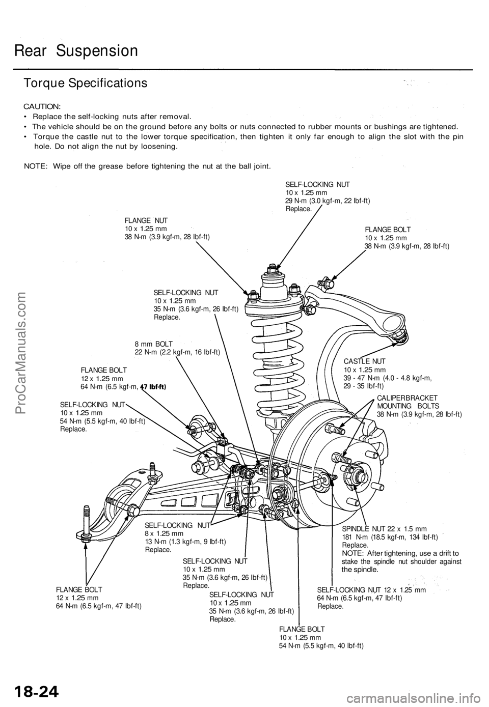
Torque Specification s
CAUTION:
• Replac e th e self-lockin g nut s afte r removal .
• Th e vehicl e shoul d b e o n th e groun d befor e an y bolt s o r nut s connecte d to rubbe r mount s o r bushing s ar e tightened .
• Torqu e th e castl e nu t t o th e lowe r torqu e specification , the n tighte n i t onl y fa r enoug h t o alig n th e slo t wit h th e pi n
hole . D o no t alig n th e nu t b y loosening .
NOTE : Wip e of f th e greas e befor e tightenin g th e nu t a t th e bal l joint .
SELF-LOCKIN G NU T10 x 1.2 5 mm29 N- m (3. 0 kgf-m , 2 2 Ibf-ft )Replace .
FLANGE NU T10 x 1.2 5 mm38 N- m (3. 9 kgf-m , 2 8 Ibf-ft ) FLANG
E BOL T10 x 1.2 5 mm38 N- m (3. 9 kgf-m , 2 8 Ibf-ft )
SELF-LOCKIN G NU T
10 x 1.2 5 mm35 N- m (3. 6 kgf-m , 2 6 Ibf-ft )Replace .
8 m m BOL T
2 2 N- m (2. 2 kgf-m , 1 6 Ibf-ft )
FLANG E BOL T
12 x 1.2 5 mm64 N- m (6. 5 kgf-m ,
SELF-LOCKIN G NU T
10 x 1.2 5 mm54 N- m (5. 5 kgf-m , 4 0 Ibf-ft )
Replace . CASTL
E NU T
10 x 1.2 5 mm39 - 4 7 N- m (4. 0 - 4. 8 kgf-m ,
2 9 - 3 5 Ibf-ft )
CALIPE R BRACKE T
MOUNTIN G BOLT S
3 8 N- m (3. 9 kgf-m , 2 8 Ibf-ft )
FLANG E BOL T
12 x 1.2 5 mm64 N- m (6. 5 kgf-m , 4 7 Ibf-ft )SELF-LOCKIN
G NU T
8 x 1.2 5 mm13 N- m (1. 3 kgf-m , 9 Ibf-ft )Replace .
SELF-LOCKIN G NU T10 x 1.2 5 mm35 N- m (3. 6 kgf-m , 2 6 Ibf-ft )Replace .
SELF-LOCKIN G NU T10 x 1.2 5 mm35 N- m (3. 6 kgf-m , 2 6 Ibf-ft )
Replace .
FLANGE BOL T
10 x 1.2 5 mm54 N- m (5. 5 kgf-m , 4 0 Ibf-ft )
SPINDL
E NU T 2 2 x 1. 5 m m
18 1 N- m (18. 5 kgf-m , 13 4 Ibf-ft )
Replace .NOTE: Afte r tightening , us e a drif t t ostak e th e spindl e nu t shoulde r agains tthe spindle .
SELF-LOCKIN G NU T 1 2 x 1.2 5 m m
6 4 N- m (6. 5 kgf-m , 4 7 Ibf-ft )
Replace .
ProCarManuals.com
Page 1247 of 1771
Rear Dampe r
Installatio n
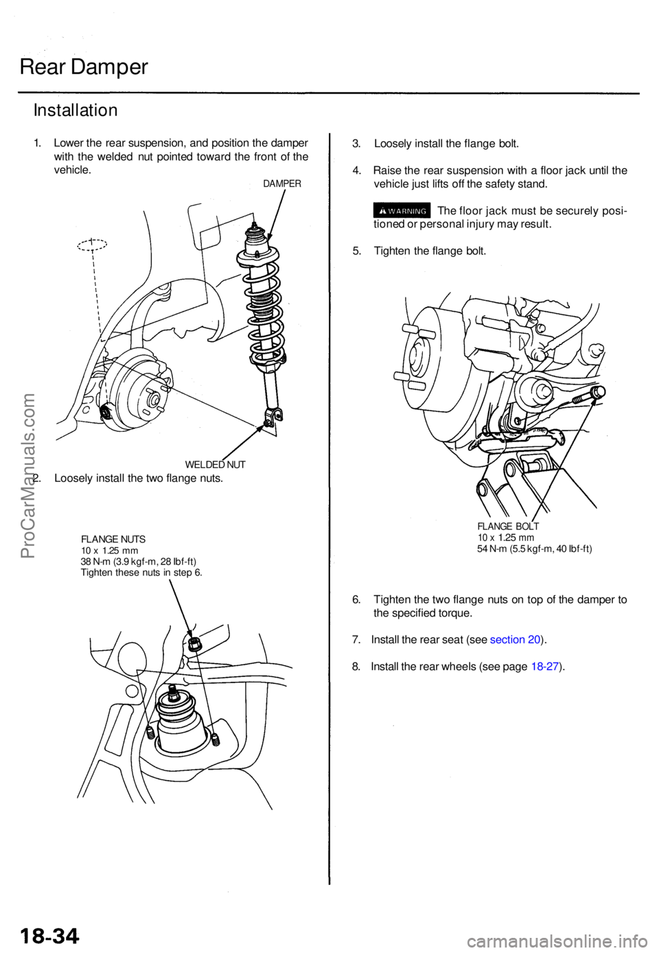
1. Lowe r th e rea r suspension , an d positio n th e dampe r
wit h th e welde d nu t pointe d towar d th e fron t o f th e
vehicle .
DAMPE R
WELDED NU T
2. Loosel y instal l th e tw o flang e nuts .
FLANG E NUT S10 x 1.2 5 mm38 N- m (3. 9 kgf-m , 2 8 Ibf-ft )
Tighte n thes e nut s i n ste p 6 .
3. Loosel y instal l th e flang e bolt .
4 . Rais e th e rea r suspensio n wit h a floo r jac k unti l th e
vehicl e jus t lift s of f th e safet y stand .
Th e floo r jac k mus t b e securel y posi -
tione d o r persona l injur y ma y result .
5 . Tighte n th e flang e bolt .
FLANG E BOL T10 x 1.2 5 mm54 N- m (5. 5 kgf-m , 4 0 Ibf-ft )
6. Tighte n th e tw o flang e nut s o n to p o f th e dampe r t o
th e specifie d torque .
7 . Instal l th e rea r sea t (se e sectio n 20 ).
8 . Instal l th e rea r wheel s (se e pag e 18-27 ).
ProCarManuals.com
Page 1261 of 1771
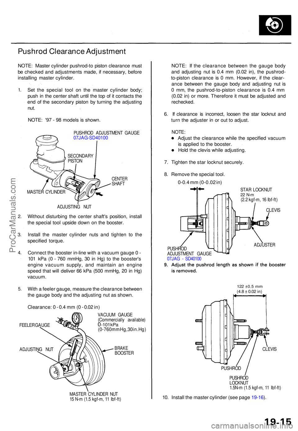
Pushrod Clearanc e Adjustmen t
NOTE: Maste r cylinde r pushrod-t o pisto n clearanc e mus t
b e checke d an d adjustment s made , i f necessary , befor e
installin g maste r cylinder .
1.
2 .
3.
4 .
5 .
Se t th e specia l too l o n th e maste r cylinde r body ;
pus h in th e cente r shaf t unti l th e to p o f i t contact s th e
en d o f th e secondar y pisto n b y turnin g th e adjustin g
nut.
NOTE : '9 7 - 9 8 model s i s shown .
PUSHRO D ADJUSTMEN T GAUG E07JAG-SD4010 0
CENTERSHAFT
ADJUSTIN G NU T
Withou t disturbin g th e cente r shaft' s position , instal l
th e specia l too l upsid e dow n o n th e booster .
Instal l th e maste r cylinde r nut s an d tighte n t o th e
specifie d torque .
Connec t th e booste r in-lin e wit h a vacuu m gaug e 0 -
10 1 kP a ( 0 - 76 0 mmHg , 3 0 in Hg ) t o th e booster' s
engin e vacuu m supply , an d maintai n a n engin e
spee d tha t wil l delive r 6 6 kP a (50 0 mmHg , 2 0 in Hg )
vacuum .
With a feele r gauge , measur e th e clearanc e betwee n
th e gaug e bod y an d th e adjustin g nu t a s shown .
Clearance : 0 - 0. 4 m m (0 - 0.0 2 in )
FEELE R GAUG E
ADJUSTIN G NU T VACUU
M GAUG E
(Commerciall y available )0 -101 kPa(0-760mmHg,30in.Hg )
BRAKEBOOSTE R
MASTER CYLINDE R NU T
1 5 N- m (1. 5 kgf-m , 1 1 Ibf-ft )
NOTE : I f th e clearanc e betwee n th e gaug e bod y
an d adjustin g nu t i s 0. 4 m m (0.0 2 in) , th e pushrod -
to-pisto n clearanc e i s 0 mm . However , i f th e clear -
anc e betwee n th e gaug e bod y an d adjustin g nu t i s
0 mm , th e pushrod-to-pisto n clearanc e i s 0. 4 m m
(0.0 2 in ) o r more . Therefor e it mus t b e adjuste d an d
rechecked .
6. I f clearanc e i s incorrect , loose n th e sta r locknu t an d
tur n th e adjuste r i n o r ou t t o adjust .
NOTE:
Adjust th e clearanc e whil e th e specifie d vacuu m
i s applie d t o th e booster .
Hol d th e clevi s whil e adjusting .
7 . Tighte n th e sta r locknu t securely .
8 . Remov e th e specia l tool .
0-0. 4 m m (0-0.0 2 in )
STA R LOCKNU T22 N- m(2.2 kgf-m , 1 6 Ibf-ft )
PUSHRO D
LOCKNU T
1.5N- m (1. 5 kgf-m , 1 1 Ibf-ft )
10. Instal l th e maste r cylinde r (se e pag e 19-16 ).
MASTE R CYLINDE RSECONDAR
Y
PISTO N
CLEVIS
ADJUSTE R
PUSHRO D
ADJUSTMEN T GAUG E
07JA G - SD4010 0
122 ±0. 5 mm(4.8 ± 0.0 2 in)
CLEVI S
PUSHRO D
ProCarManuals.com
Page 1307 of 1771
ABS Functio n Tes t
Modulato r Functio n Chec k
NOTE : Thi s inspectio n determine s whethe r th e basi c
brake syste m continue s t o operat e normall y whe n th e
modulato r uni t flui d pressur e i s low .
CAUTION :
Thi s inspectio n i s mad e b y relievin g th e high-pres -
sur e flui d i n th e modulato r uni t an d checkin g fo r
brak e operation . Afte r inspection , b e sur e t o ad d
fres h brak e flui d t o th e specifie d leve l o f th e reser -
voir , an d star t th e engin e t o restor e th e AB S t o it s
norma l operatin g condition .
D o no t spil l brak e flui d o n th e car ; i t ma y damag e th e
paint ; i f brak e flui d doe s contac t th e paint , was h i t
of f immediatel y wit h water .
D o no t reus e th e draine d brak e fluid .
D o no t loose n th e relie f plu g o n th e accumulator .
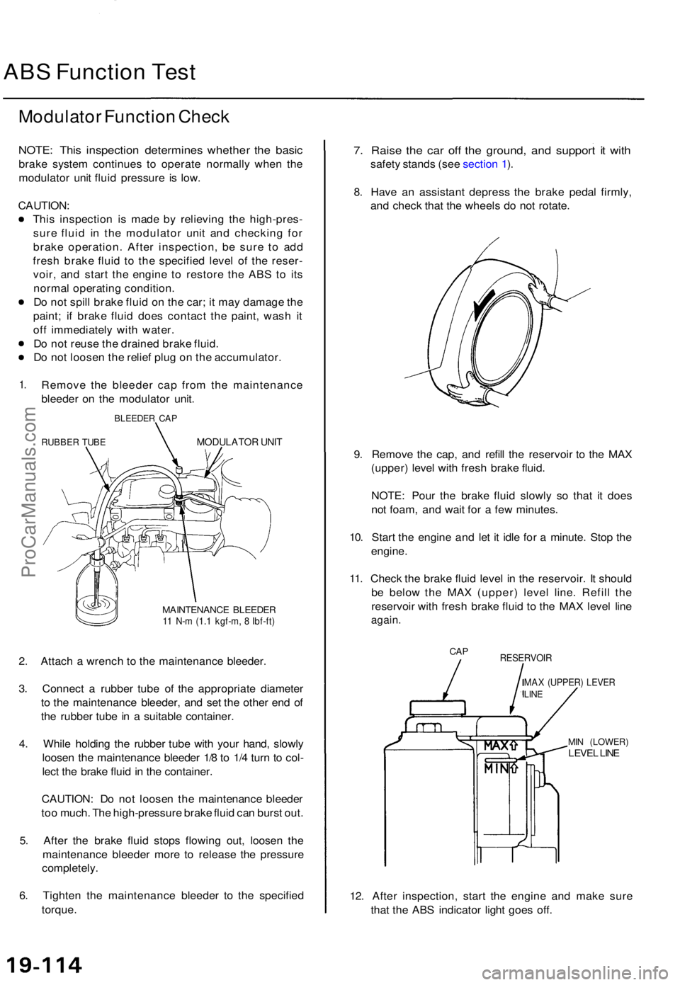
1.Remov e th e bleede r ca p fro m th e maintenanc e
bleede r o n th e modulato r unit .
BLEEDE R CA P
RUBBE R TUB EMODULATO R UNI T
MAINTENANC E BLEEDE R11 N- m (1. 1 kgf-m , 8 Ibf-ft )
2. Attac h a wrenc h t o th e maintenanc e bleeder .
3 . Connec t a rubbe r tub e o f th e appropriat e diamete r
t o th e maintenanc e bleeder , an d se t th e othe r en d o f
th e rubbe r tub e in a suitabl e container .
4 . Whil e holdin g th e rubbe r tub e wit h you r hand , slowl y
loose n th e maintenanc e bleede r 1/ 8 to 1/ 4 tur n t o col -
lec t th e brak e flui d in th e container .
CAUTION : D o no t loose n th e maintenanc e bleede r
to o much . Th e high-pressur e brak e flui d ca n burs t out .
5 . Afte r th e brak e flui d stop s flowin g out , loose n th e
maintenanc e bleede r mor e t o releas e th e pressur e
completely .
6 . Tighte n th e maintenanc e bleede r t o th e specifie d
torque .
7. Rais e th e ca r of f th e ground , an d suppor t i t wit h
safet y stand s (se e sectio n 1 ).
8 .Hav e a n assistan t depres s th e brak e peda l firmly ,
an d chec k tha t th e wheel s d o no t rotate .
9 . Remov e th e cap , an d refil l th e reservoi r t o th e MA X
(upper ) leve l wit h fres h brak e fluid .
NOTE : Pou r th e brak e flui d slowl y s o tha t i t doe s
no t foam , an d wai t fo r a fe w minutes .
10 . Star t th e engin e an d le t i t idl e fo r a minute . Sto p th e
engine .
11 . Chec k th e brak e flui d leve l i n th e reservoir . I t shoul d
b e belo w th e MA X (upper ) leve l line . Refil l th e
reservoi r wit h fres h brak e flui d t o th e MA X leve l lin e
again .
CAPRESERVOI R
MAX (UPPER ) LEVE RLINE
MIN (LOWER )LEVEL LIN E
12. Afte r inspection , star t th e engin e an d mak e sur e
tha t th e AB S indicato r ligh t goe s off .
ProCarManuals.com
Page 1308 of 1771
Modulator Uni t
Relievin g Syste m Pressur e
CAUTION :
Be sur e t o drai n th e high-pressur e brak e flui d com -
pletel y befor e performin g th e modulato r functio n
check, disposin g th e modulato r unit, accumulato r
and AB S pum p moto r replacement .
D o no t spil l brak e flui d o n th e car ; i t ma y damag e th e
paint ; i f brak e flui d doe s contac t th e
paint , wash i t
of f immediatel y wit h water .
Do no t reus e th e draine d brak e fluid .
D o no t loose n th e relie f plu g o n th e accumulator .
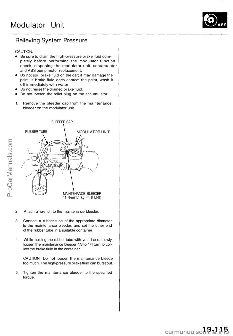
1 . Remov e th e bleede r ca p fro m th e maintenanc e
bleeder o n th e modulato r unit .
RUBBE R TUB E
BLEEDE R CA P
MODULATOR UNIT
MAINTENANC E BLEEDE R11 N-m(1. 1 kgf-m, 8 Ibf-ft)
2. Attac h a wrenc h t o th e maintenanc e bleeder .
3 . Connec t a rubbe r tub e o f th e appropriat e diamete r
t o th e maintenanc e bleeder , an d se t th e othe r en d
o f th e rubbe r tub e in a suitabl e container .
4 . Whil e holdin g th e rubbe r tub e wit h you r hand , slowl y
loosen th e maintenanc e bleede r 1/ 8 to 1/ 4 tur n to col -
lect th e brak e flui d in th e container .
CAUTION : D o no t loose n th e maintenanc e bleede r
to o much . Th e high-pressur e brak e flui d ca n burs t out .
5 . Tighte n th e maintenanc e bleede r t o th e specifie d
torque .
ProCarManuals.com
Page 1310 of 1771
Modulator Uni t
Brak e Flui d Replacement/Bleedin g (cont'd )
6. Star t th e engin e an d le t i t idl e fo r a minute . Sto p th e
engine .
7 . Chec k th e brak e flui d leve l i n th e reservoir . I t shoul d
b e belo w th e MA X (upper ) leve l line .
8 . Repea t th e step s 4 throug h 7 to drai n th e res t o f th e
brak e flui d fro m th e modulato r unit .
NOTE : Th e modulato r ha s a capacit y o f approximatel y
150 ( 5 fl-oz , 5. 3 Imp-oz) . Approximatel y 3 5 - 4 5
(1 1/6- 1 1/ 2 fl-oz , 1.2-1. 6 Imp-oz ) o f th e flui d i s
draine d a t eac h try .
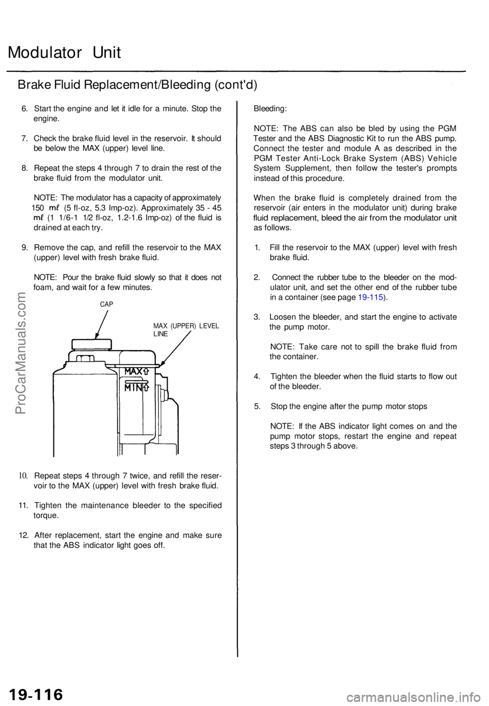
9 . Remov e th e cap , an d refil l th e reservoi r t o th e MA X
(upper ) leve l wit h fres h brak e fluid .
NOTE : Pou r th e brak e flui d slowl y s o tha t i t doe s no t
foam , an d wai t fo r a fe w minutes .
10.
CA P
MA X (UPPER ) LEVE LLINE
Repea t step s 4 throug h 7 twice , an d refil l th e reser -
voi r t o th e MA X (upper ) leve l wit h fres h brak e fluid .
11 . Tighten the maintenanc e bleede r t o th e specifie d
torque .
12 . Afte r replacement , star t th e engin e an d mak e sur e
tha t th e AB S indicator light goe s off .
Bleeding :
NOTE: Th e AB S ca n als o b e ble d b y usin g th e PG M
Teste r an d th e AB S Diagnosti c Ki t t o ru n th e AB S pump .
Connec t th e teste r an d modul e A as describe d i n th e
PG M Teste r Anti-Loc k Brak e Syste m (ABS ) Vehicl e
Syste m Supplement , the n follo w th e tester' s prompt s
instea d o f thi s procedure .
Whe n th e brak e flui d i s completel y draine d fro m th e
reservoi r (ai r enter s i n th e modulato r unit ) durin g brak e
fluid replacement , blee d th e ai r fro m th e modulato r uni t
as follows .
1 . Fil l th e reservoi r t o th e MA X (upper ) leve l wit h fres h
brak e fluid .
2 . Connec t th e rubbe r tub e t o th e bleede r o n th e mod -
ulato r unit , an d se t th e othe r en d o f th e rubbe r tub e
i n a containe r (se e page 19-115 ).
3 . Loose n th e bleeder , an d star t th e engin e t o activat e
th e pum p motor .
NOTE : Tak e car e no t t o spil l th e brak e flui d fro m
th e container .
4 . Tighte n th e bleede r whe n th e flui d start s t o flo w ou t
o f th e bleeder .
5 . Sto p th e engin e afte r th e pum p moto r stop s
NOTE : I f th e AB S indicato r ligh t come s o n an d th e
pum p moto r stops , restar t th e engin e an d repea t
step s 3 throug h 5 above .
ProCarManuals.com