Page 689 of 1771
Service Precautions
Handling of Special Nuts and Bolts
Because the front sub frame sections on this vehicle are
constructed with aluminum alloys, use only the special
"Dacro" type nuts and bolts recommended by Acura.
NOTE:
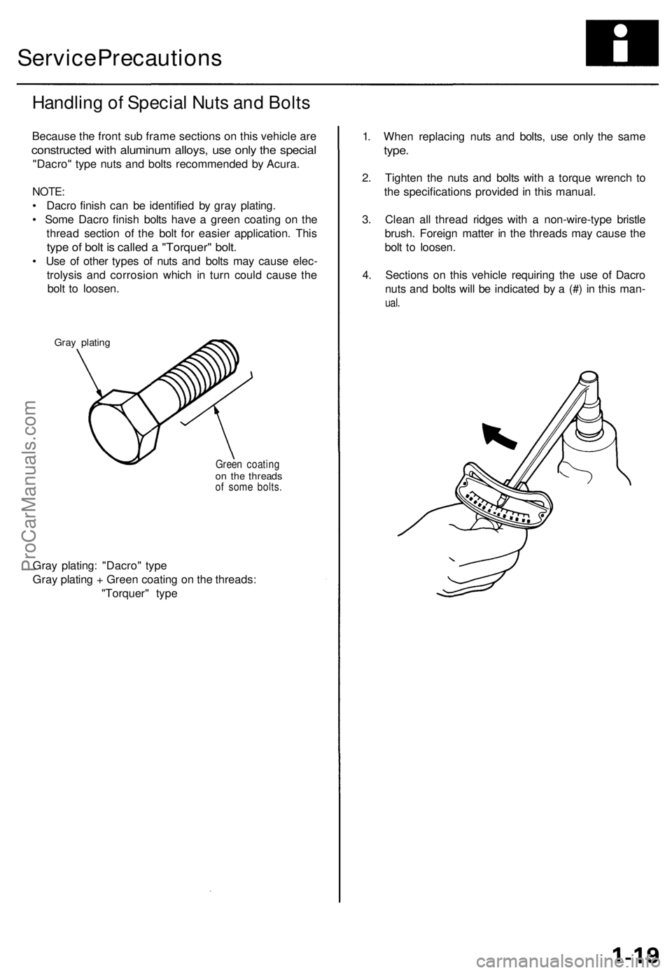
• Dacro finish can be identified by gray plating.
• Some Dacro finish bolts have a green coating on the
thread section of the bolt for easier application. This
type of bolt is called a "Torquer" bolt.
• Use of other types of nuts and bolts may cause elec-
trolysis and corrosion which in turn could cause the
bolt to loosen.
Gray plating
Green coating
on the threads
of some bolts.
Gray plating: "Dacro" type
Gray plating + Green coating on the threads:
"Torquer" type
1. When replacing nuts and bolts, use only the same
type.
2. Tighten the nuts and bolts with a torque wrench to
the specifications provided in this manual.
3. Clean all thread ridges with a non-wire-type bristle
brush. Foreign matter in the threads may cause the
bolt to loosen.
4. Sections on this vehicle requiring the use of Dacro
nuts and bolts will be indicated by a (#) in this man-
ual.ProCarManuals.com
Page 727 of 1771
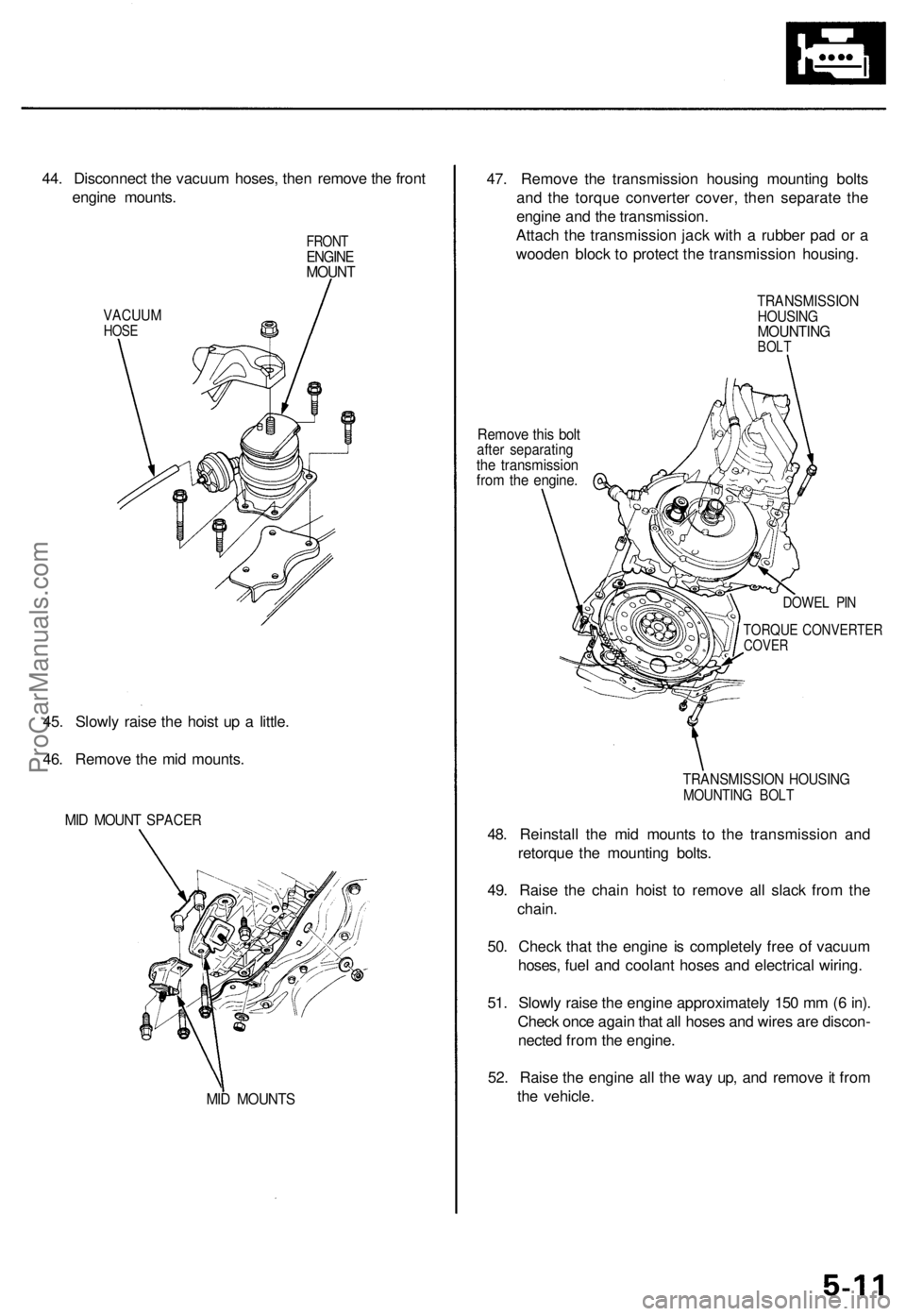
44. Disconnect the vacuum hoses, then remove the front
engine mounts.
VACUUM
HOSE
FRONT
ENGINE
MOUNT
45. Slowly raise the hoist up a little.
46. Remove the mid mounts.
MID MOUNT SPACER
MID MOUNTS
47. Remove the transmission housing mounting bolts
and the torque converter cover, then separate the
engine and the transmission.
Attach the transmission jack with a rubber pad or a
wooden block to protect the transmission housing.
Remove this bolt
after separating
the transmission
from the engine.
TRANSMISSION
HOUSING
MOUNTING
BOLT
DOWEL PIN
TORQUE CONVERTER
COVER
TRANSMISSION HOUSING
MOUNTING BOLT
48. Reinstall the mid mounts to the transmission and
retorque the mounting bolts.
49. Raise the chain hoist to remove all slack from the
chain.
50. Check that the engine is completely free of vacuum
hoses, fuel and coolant hoses and electrical wiring.
51. Slowly raise the engine approximately 150 mm (6 in).
Check once again that all hoses and wires are discon-
nected from the engine.
52. Raise the engine all the way up, and remove it from
the vehicle.ProCarManuals.com
Page 757 of 1771
Camshaft
Inspection
NOTE:
• Do not rotate the camshaft during inspection.
• Remove the rocker arms and rocker shafts.
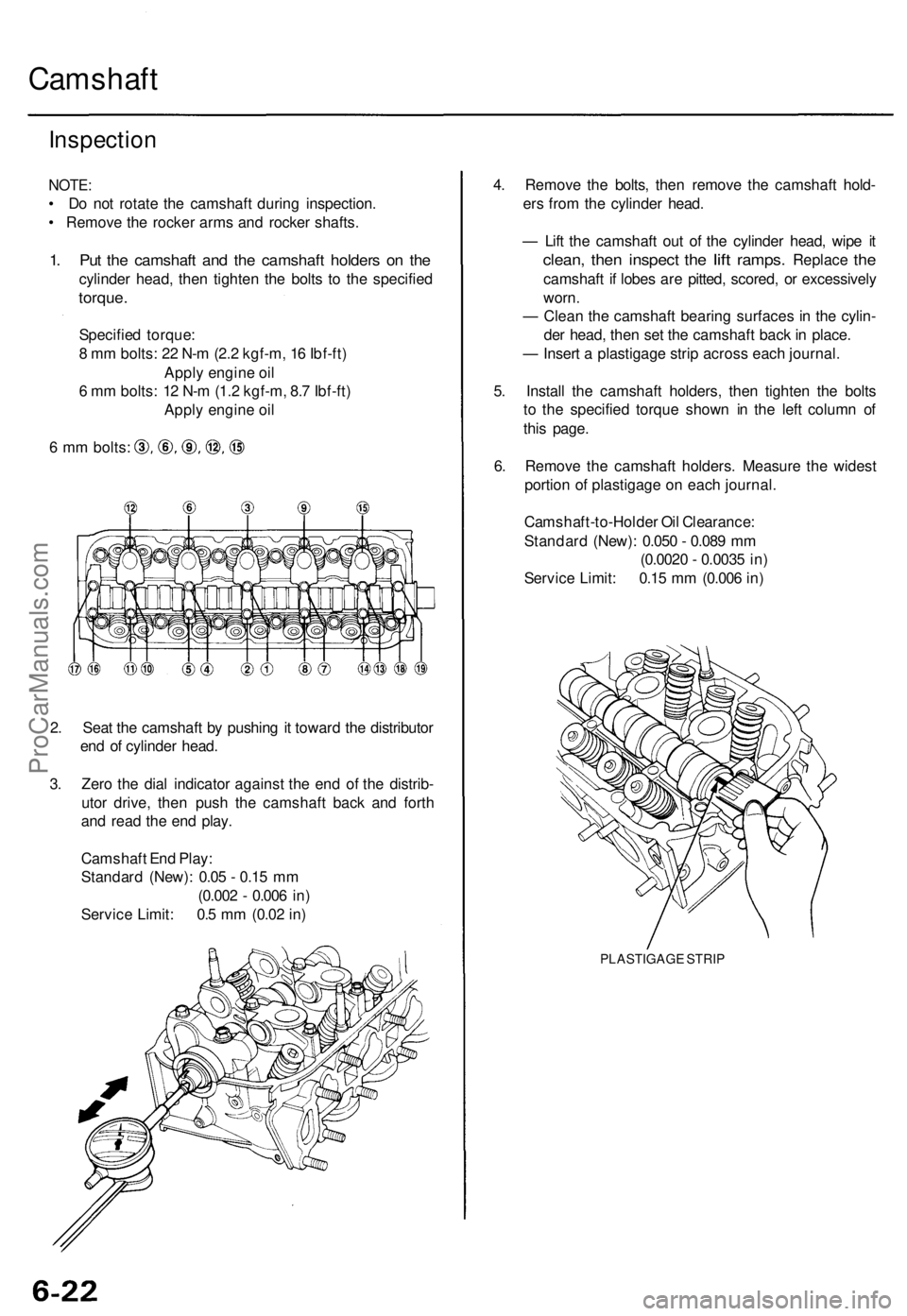
1. Put the camshaft and the camshaft holders on the
cylinder head, then tighten the bolts to the specified
torque.
Specified torque:
8 mm bolts: 22 N-m (2.2 kgf-m, 16 Ibf-ft)
Apply engine oil
6 mm bolts: 12 N-m (1.2 kgf-m, 8.7 Ibf-ft)
Apply engine oil
6 mm bolts:
2. Seat the camshaft by pushing it toward the distributor
end of cylinder head.
3. Zero the dial indicator against the end of the distrib-
utor drive, then push the camshaft back and forth
and read the end play.
Camshaft End Play:
Standard (New): 0.05 - 0.15 mm
(0.002 - 0.006 in)
Service Limit: 0.5 mm (0.02 in)
4. Remove the bolts, then remove the camshaft hold-
ers from the cylinder head.
— Lift the camshaft out of the cylinder head, wipe it
clean,
then
inspect
the
lift
ramps.
Replace
the
camshaft if lobes are pitted, scored, or excessively
worn.
— Clean the camshaft bearing surfaces in the cylin-
der head, then set the camshaft back in place.
— Insert a plastigage strip across each journal.
5. Install the camshaft holders, then tighten the bolts
to the specified torque shown in the left column of
this page.
6. Remove the camshaft holders. Measure the widest
portion of plastigage on each journal.
Camshaft-to-Holder Oil Clearance:
Standard (New): 0.050 - 0.089 mm
(0.0020 - 0.0035 in)
Service Limit: 0.15 mm (0.006 in)
PLASTIGAGE STRIPProCarManuals.com
Page 771 of 1771
4. Tighten each bolt two turns at a time in the sequence
shown below to ensure that the rockers do not bind
on the valves.
Specified torque:
8 mm bolts: 22 N-m (2.2 kgf-m, 16 Ibf-ft)
Apply engine oil
6 mm bolts: 12 N-m (1.2 kgf-m, 8.7 Ibf-ft)
Apply engine oil
6 mm bolts:
5. Torque the bolts in the sequence shown.ProCarManuals.com
Page 773 of 1771
Cylinder Hea d
Installatio n (cont'd )
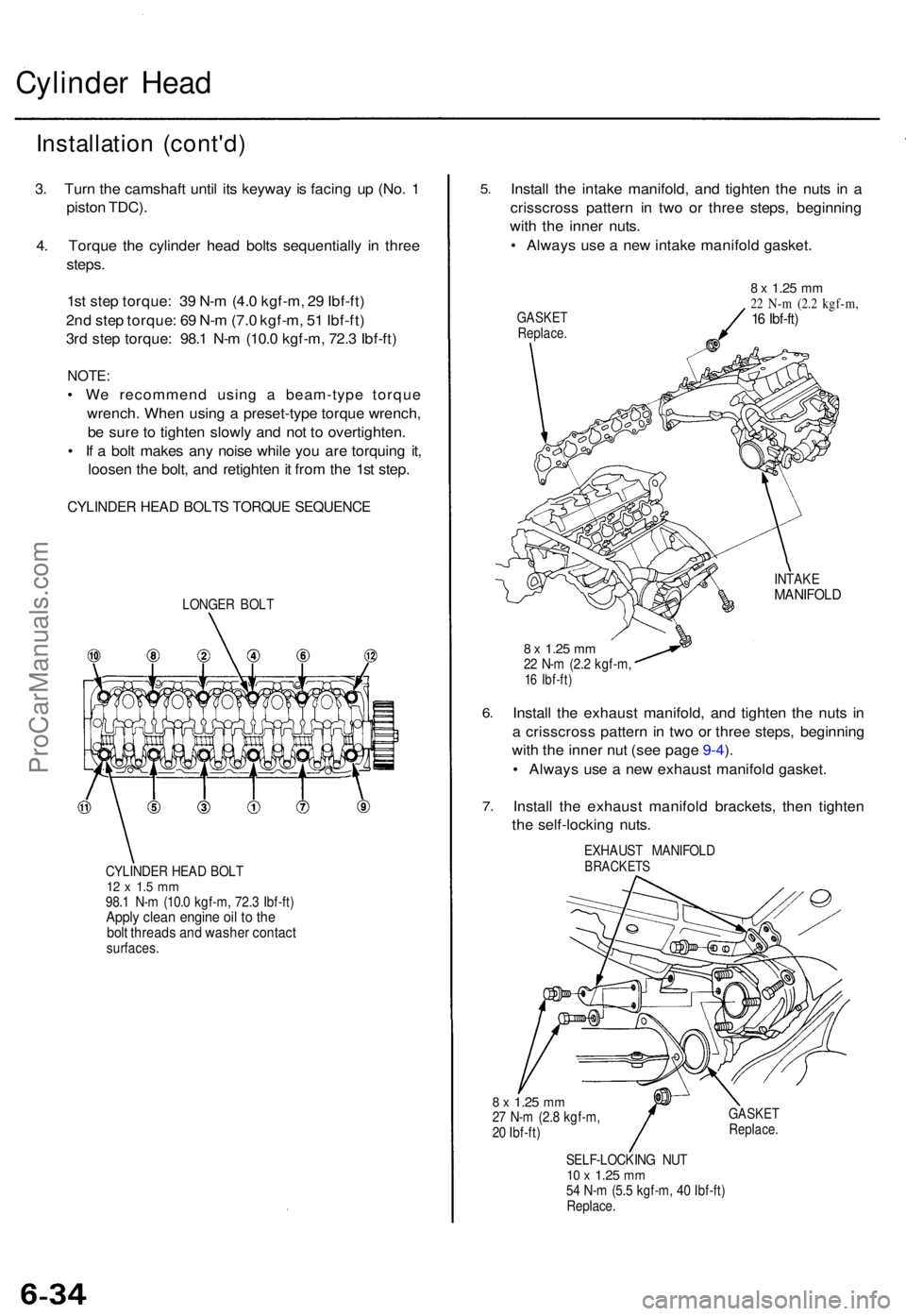
3. Tur n th e camshaf t unti l it s keywa y i s facin g u p (No . 1
pisto n TDC) .
4 . Torqu e th e cylinde r hea d bolt s sequentiall y i n thre e
steps .
1s t ste p torque : 3 9 N- m (4. 0 kgf-m , 2 9 Ibf-ft )
2n d ste p torque : 6 9 N- m (7. 0 kgf-m , 5 1 Ibf-ft )
3r d ste p torque : 98. 1 N- m (10. 0 kgf-m , 72. 3 Ibf-ft )
NOTE :
• W e recommen d usin g a beam-typ e torqu e
wrench . Whe n usin g a preset-typ e torqu e wrench ,
b e sur e t o tighte n slowl y an d no t t o overtighten .
• I f a bol t make s an y nois e whil e yo u ar e torquin g it ,
loose n th e bolt , an d retighte n it fro m th e 1s t step .
CYLINDE R HEA D BOLT S TORQU E SEQUENC E
LONGER BOL T
CYLINDE R HEA D BOL T
12 x 1. 5 m m98. 1 N- m (10. 0 kgf-m , 72. 3 Ibf-ft )Apply clea n engin e oi l t o th ebol t thread s an d washe r contac tsurfaces .
5.
6.
7 .
Instal l th e intak e manifold , an d tighte n th e nut s i n a
crisscros s patter n i n tw o o r thre e steps , beginnin g
wit h th e inne r nuts .
• Alway s us e a ne w intak e manifol d gasket .
GASKE TReplace .
8 x 1.2 5 mm22 N- m (2. 2 kgf-m ,16 Ibf-ft )
INTAK EMANIFOL D
8 x 1.2 5 mm22 N- m (2. 2 kgf-m ,16 Ibf-ft )
Install th e exhaus t manifold , an d tighte n th e nut s i n
a crisscros s patter n in tw o o r thre e steps , beginnin g
wit h th e inne r nu t (se e pag e 9-4 ).
• Alway s us e a ne w exhaus t manifol d gasket .
Instal l th e exhaus t manifol d brackets , the n tighte n
th e self-lockin g nuts .
EXHAUS T MANIFOL DBRACKETS
8 x 1.2 5 mm27 N- m (2. 8 kgf-m ,
2 0 Ibf-ft )GASKE TReplace .
SELF-LOCKIN G NU T10 x 1.2 5 mm54 N- m (5. 5 kgf-m , 4 0 Ibf-ft )
Replace .
ProCarManuals.com
Page 775 of 1771
Cylinder Head
Installation (cont'd)
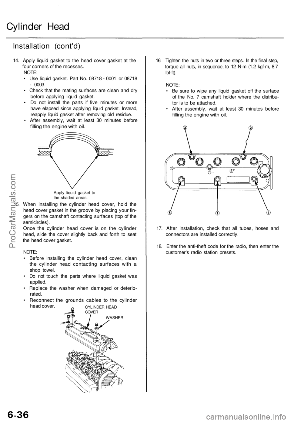
14. Apply liquid gasket to the head cover gasket at the
four corners of the recesses.
NOTE:
• Use liquid gasket. Part No. 08718 - 0001 or 08718
- 0003.
• Check that the mating surfaces are clean and dry
before applying liquid gasket.
• Do not install the parts if five minutes or more
have elapsed since applying liquid gasket. Instead,
reapply liquid gasket after removing old residue.
• After assembly, wait at least 30 minutes before
filling the engine with oil.
15.
Apply liquid gasket to
the shaded areas.
When installing the cylinder head cover, hold the
head cover gasket in the groove by placing your fin-
gers on the camshaft contacting surfaces (top of the
semicircles).
Once the cylinder head cover is on the cylinder
head, slide the cover slightly back and forth to seat
the head cover gasket.
NOTE:
• Before installing the cylinder head cover, clean
the cylinder head contacting surfaces with a
shop towel.
• Do not touch the parts where liquid gasket was
applied.
• Replace the washer when damaged or deterio-
rated.
• Reconnect the grounds cables to the cylinder
head cover.
16. Tighten the nuts in two or three steps. In the final step,
torque all nuts, in sequence, to 12 N-m (1.2 kgf-m, 8.7
Ibf-ft).
NOTE:
• Be sure to wipe any liquid gasket off the surface
of the No. 7 camshaft holder where the distribu-
tor is to be attached.
• After assembly, wait at least 30 minutes before
filling the engine with oil.
17. After installation, check that all tubes, hoses and
connectors are installed correctly.
18. Enter the anti-theft code for the radio, then enter the
customer's radio station presets.
CYLINDER HEAD
COVER
WASHERProCarManuals.com
Page 781 of 1771
Main Bearings
Clearance
1. To check main bearing-to-journal oil clearance,
remove the main caps and bearing halves.
2. Clean each main journal and bearing half with a
clean shop towel.
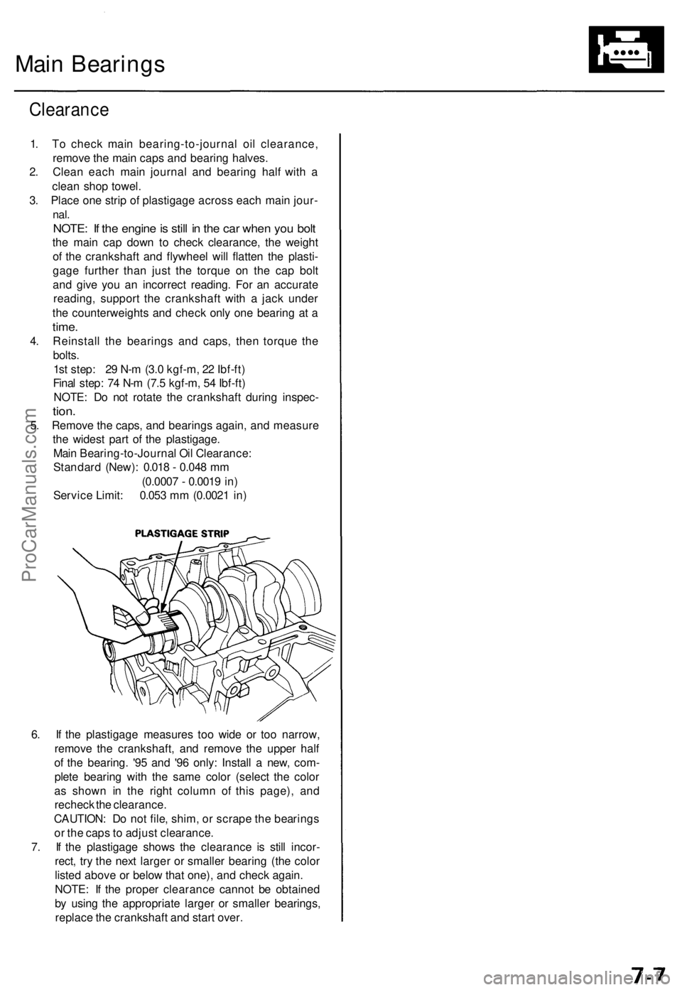
3. Place one strip of plastigage across each main jour-
nal.
NOTE: If the engine is still in the car when you bolt
the main cap down to check clearance, the weight
of the crankshaft and flywheel will flatten the plasti-
gage further than just the torque on the cap bolt
and give you an incorrect reading. For an accurate
reading, support the crankshaft with a jack under
the counterweights and check only one bearing at a
time.
4. Reinstall the bearings and caps, then torque the
bolts.
1st step: 29 N-m (3.0 kgf-m, 22 Ibf-ft)
Final step: 74 N-m (7.5 kgf-m, 54 Ibf-ft)
NOTE: Do not rotate the crankshaft during inspec-
tion.
5. Remove the caps, and bearings again, and measure
the widest part of the plastigage.
Main Bearing-to-Journal Oil Clearance:
Standard (New): 0.018 - 0.048 mm
(0.0007 - 0.0019 in)
Service Limit: 0.053 mm (0.0021 in)
6. If the plastigage measures too wide or too narrow,
remove the crankshaft, and remove the upper half
of the bearing. '95 and '96 only: Install a new, com-
plete bearing with the same color (select the color
as shown in the right column of this page), and
recheck the clearance.
CAUTION: Do not file, shim, or scrape the bearings
or the caps to adjust clearance.
7. If the plastigage shows the clearance is still incor-
rect, try the next larger or smaller bearing (the color
listed above or below that one), and check again.
NOTE: If the proper clearance cannot be obtained
by using the appropriate larger or smaller bearings,
replace the crankshaft and start over.ProCarManuals.com
Page 784 of 1771
Connecting Rod Bearings
Clearance
1. Remove the connecting rod cap and bearing half.
2. Clean the crankshaft rod journal and bearing half
with a clean shop towel.
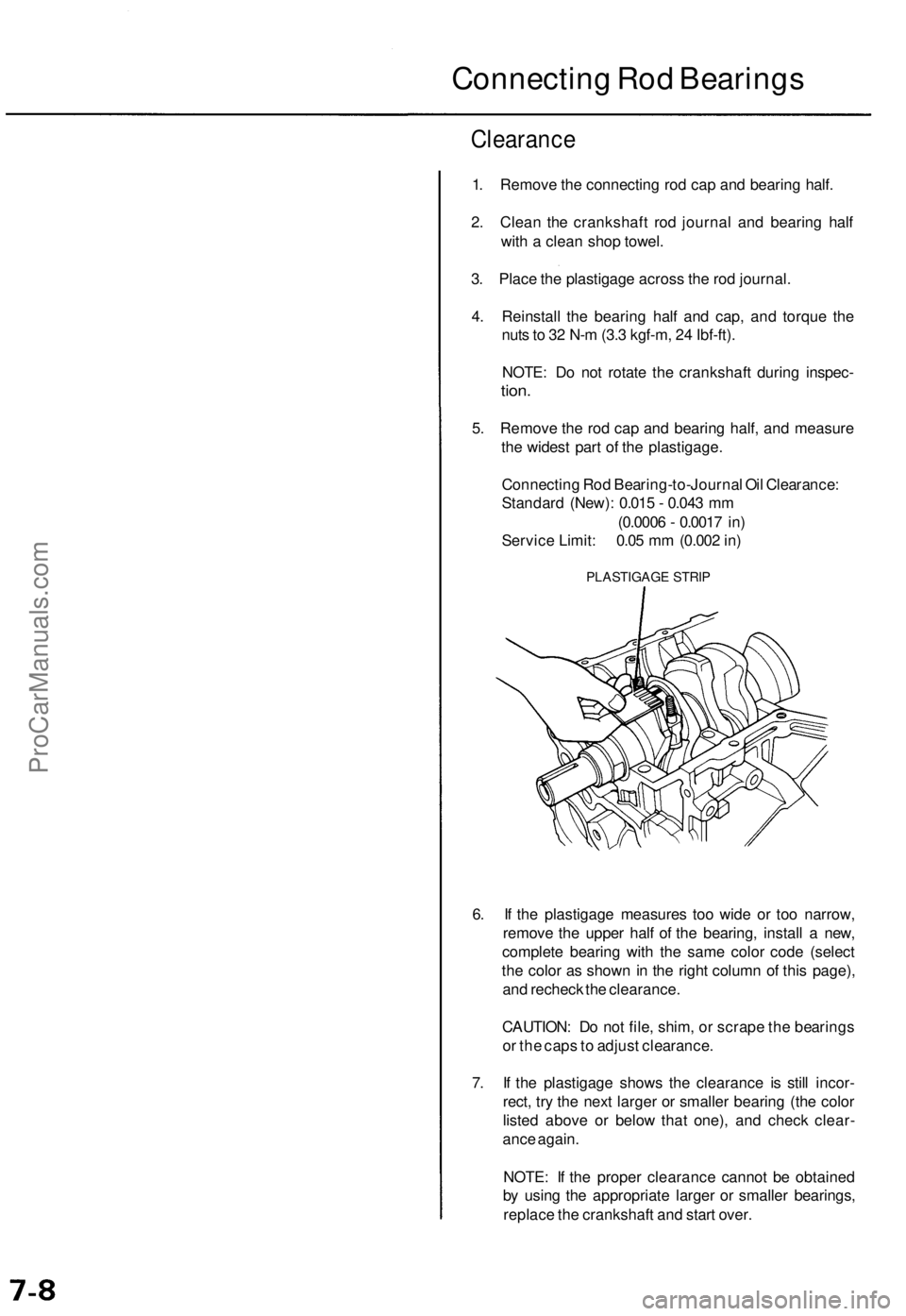
3. Place the plastigage across the rod journal.
4. Reinstall the bearing half and cap, and torque the
nuts to 32 N-m (3.3 kgf-m, 24 Ibf-ft).
NOTE: Do not rotate the crankshaft during inspec-
tion.
5. Remove the rod cap and bearing half, and measure
the widest part of the plastigage.
Connecting Rod Bearing-to-Journal Oil Clearance:
Standard (New): 0.015 - 0.043 mm
(0.0006 - 0.0017 in)
Service Limit: 0.05 mm (0.002 in)
PLASTIGAGE STRIP
6. If the plastigage measures too wide or too narrow,
remove the upper half of the bearing, install a new,
complete bearing with the same color code (select
the color as shown in the right column of this page),
and recheck the clearance.
CAUTION: Do not file, shim, or scrape the bearings
or the caps to adjust clearance.
7. If the plastigage shows the clearance is still incor-
rect, try the next larger or smaller bearing (the color
listed above or below that one), and check clear-
ance again.
NOTE: If the proper clearance cannot be obtained
by using the appropriate larger or smaller bearings,
replace the crankshaft and start over.ProCarManuals.com