Page 360 of 1771
1. Remove the eight 6 mm bolts and one 8 mm bolt
securing the regulator valve body, then remove the
regulator valve body.
2. Remove the stator shaft, stop shaft, and the regula-
tor separator plate.
3. Remove the three 6 mm bolts and two 8 mm bolts
securing the ATF pump body, then remove the ATF
pump body.
4. Remove the ATF pump driven gear shaft, ATF pump
gears, torque converter check valve, and spring.
5. Remove the four bolts securing the accumulator
cover, then remove the accumulator cover.
NOTE: The accumulator cover is spring loaded. To
prevent stripping the threads in the torque converter
housing, press down on the accumulator cover
while unscrewing the bolts in a crisscross pattern.
6. Remove the eight ATF feed pipes from the accumu-
lator body.
7. Remove the eight 6 mm bolts and seven 6 mm spe-
cial bolts securing the accumulator body, then
remove the accumulator body.
8. Remove the torque converter housing separator
plate with three dowel pins.ProCarManuals.com
Page 376 of 1771
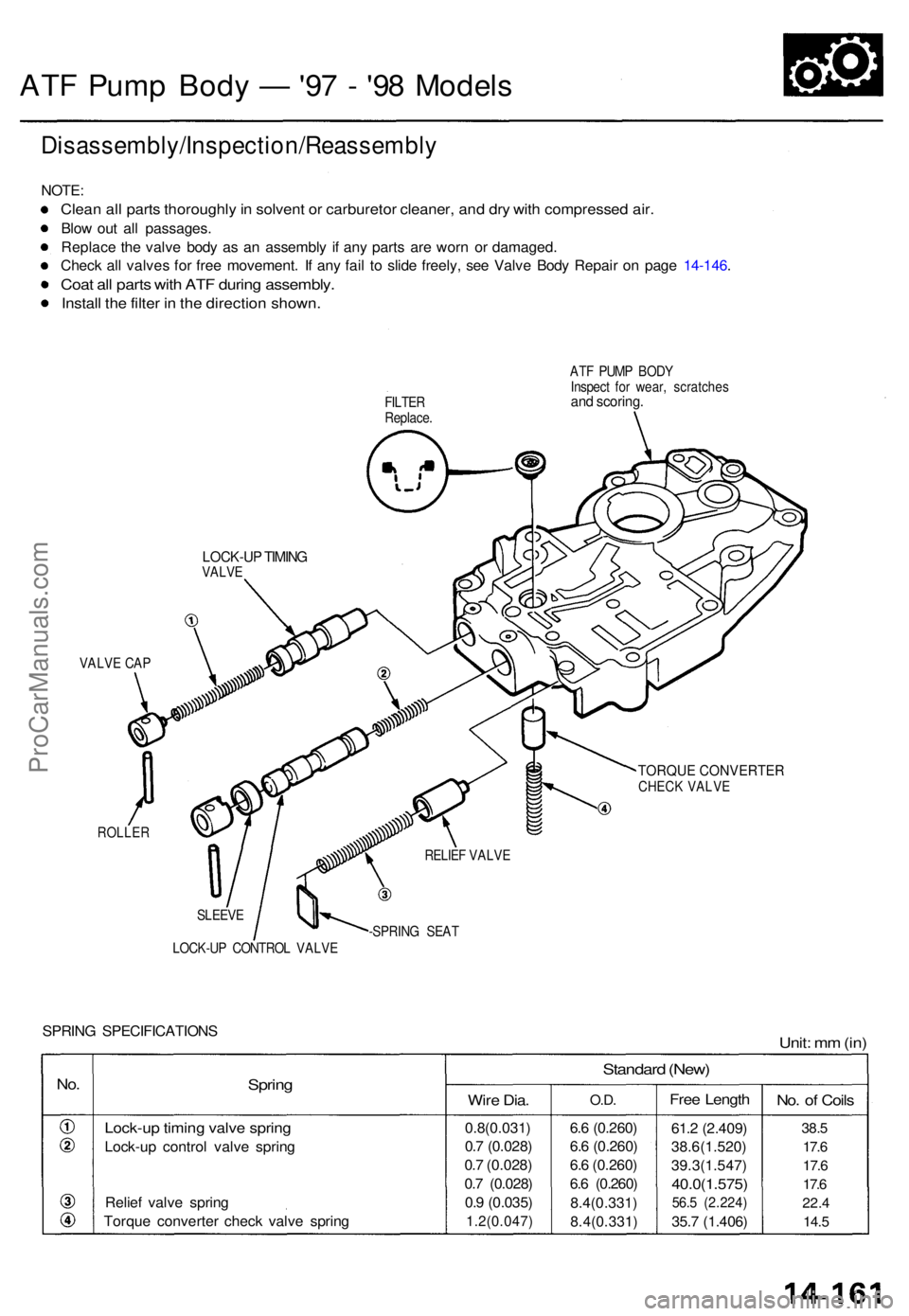
ATF Pum p Bod y — '97 - '9 8 Model s
Disassembly/Inspection/Reassembl y
NOTE:
Clean al l part s thoroughl y in solven t o r carbureto r cleaner , an d dr y wit h compresse d air .
Blow ou t al l passages .
Replac e th e valv e bod y a s a n assembl y i f an y part s ar e wor n o r damaged .
Chec k al l valve s fo r fre e movement . I f an y fai l t o slid e freely , se e Valv e Bod y Repai r o n pag e 14-146 .
Coat al l part s wit h AT F durin g assembly .
Install th e filte r i n th e directio n shown .
FILTER
Replace . AT
F PUM P BOD Y
Inspec t fo r wear , scratche sand scoring .
TORQUE CONVERTERCHECK VALVE
ROLLE R
SLEEVE
LOCK-U P CONTRO L VALV E -SPRIN
G SEA T
SPRIN G SPECIFICATION SUnit: m m (in )
No.Sprin g
Lock-u p timin g valv e sprin g
Lock-u p contro l valv e sprin g
Relie f valv e sprin g
Torqu e converte r chec k valv e sprin g
Standar d (New )
Wire Dia .
0.8(0.031 )
0. 7 (0.028 )
0. 7 (0.028 )
0. 7 (0.028 )
0. 9 (0.035 )
1.2(0.047 )
O.D.
6.6 (0.260 )
6. 6 (0.260 )
6. 6 (0.260 )
6. 6 (0.260 )
8.4(0.331 )
8.4(0.331 )
Free Lengt h
61.2 (2.409 )
38.6(1.520 )
39.3(1.547 )
40.0(1.575)
56.5 (2.224 )
35.7 (1.406 )
No. o f Coil s
38.5
17. 6
17. 6
17. 6
22. 4
14. 5
VALV E CA P
RELIEF VALV E
LOCK-U P TIMIN GVALV E
ProCarManuals.com
Page 389 of 1771
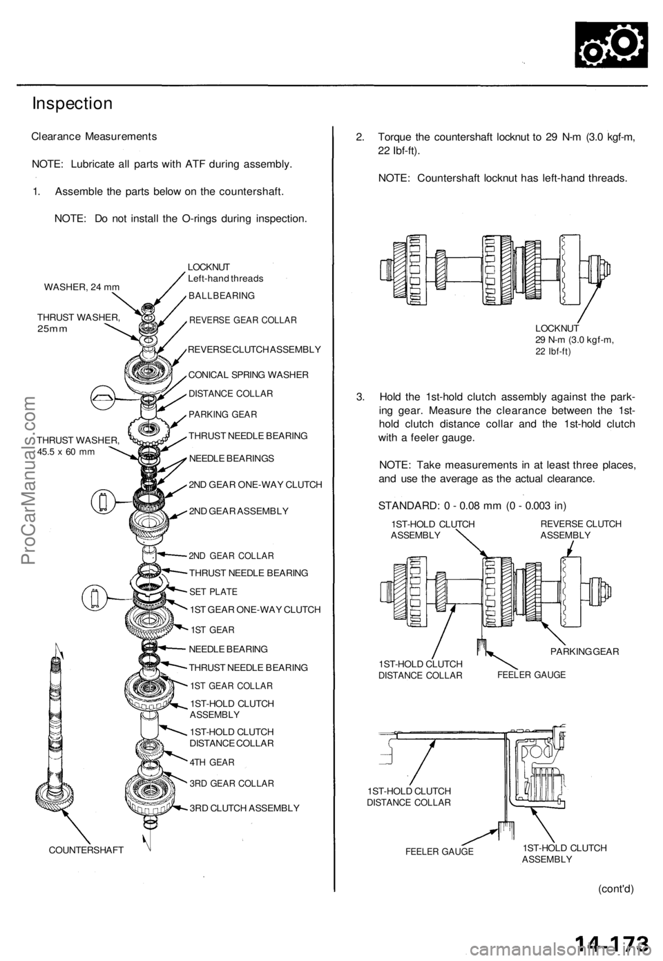
Inspection
Clearance Measurements
NOTE: Lubricate all parts with ATF during assembly.
1. Assemble the parts below on the countershaft.
NOTE: Do not install the O-rings during inspection.
WASHER, 24 mm
THRUST WASHER,
25mm
THRUST WASHER,
45.5
x 60 mm
COUNTERSHAFT
LOCKNUT
Left-hand threads
BALLBEARING
REVERSE GEAR COLLAR
REVERSE CLUTCH ASSEMBLY
CONICAL SPRING WASHER
DISTANCE COLLAR
PARKING GEAR
THRUST NEEDLE BEARING
NEEDLE BEARINGS
2ND GEAR ONE-WAY CLUTCH
2ND GEAR ASSEMBLY
2ND GEAR COLLAR
THRUST NEEDLE BEARING
SET PLATE
1ST GEAR ONE-WAY CLUTCH
1ST GEAR
NEEDLE BEARING
THRUST NEEDLE BEARING
1ST GEAR COLLAR
1ST-HOLD CLUTCH
ASSEMBLY
1ST-HOLD CLUTCH
DISTANCE COLLAR
4TH GEAR
3RD GEAR COLLAR
3RD CLUTCH ASSEMBLY
2. Torque the countershaft locknut to 29 N-m (3.0 kgf-m,
22 Ibf-ft).
NOTE: Countershaft locknut has left-hand threads.
LOCKNUT
29 N-m (3.0 kgf-m,
22 Ibf-ft)
3. Hold the 1st-hold clutch assembly against the park-
ing gear. Measure the clearance between the 1st-
hold clutch distance collar and the 1st-hold clutch
with a feeler gauge.
NOTE: Take measurements in at least three places,
and use the average as the actual clearance.
STANDARD: 0 - 0.08 mm (0 - 0.003 in)
1ST-HOLD CLUTCH
ASSEMBLY
REVERSE CLUTCH
ASSEMBLY
PARKING GEAR
1ST-HOLD CLUTCH
DISTANCE COLLAR
FEELER GAUGE
1ST-HOLD CLUTCH
DISTANCE COLLAR
FEELER GAUGE
1ST-HOLD CLUTCH
ASSEMBLY
(cont'd)ProCarManuals.com
Page 409 of 1771
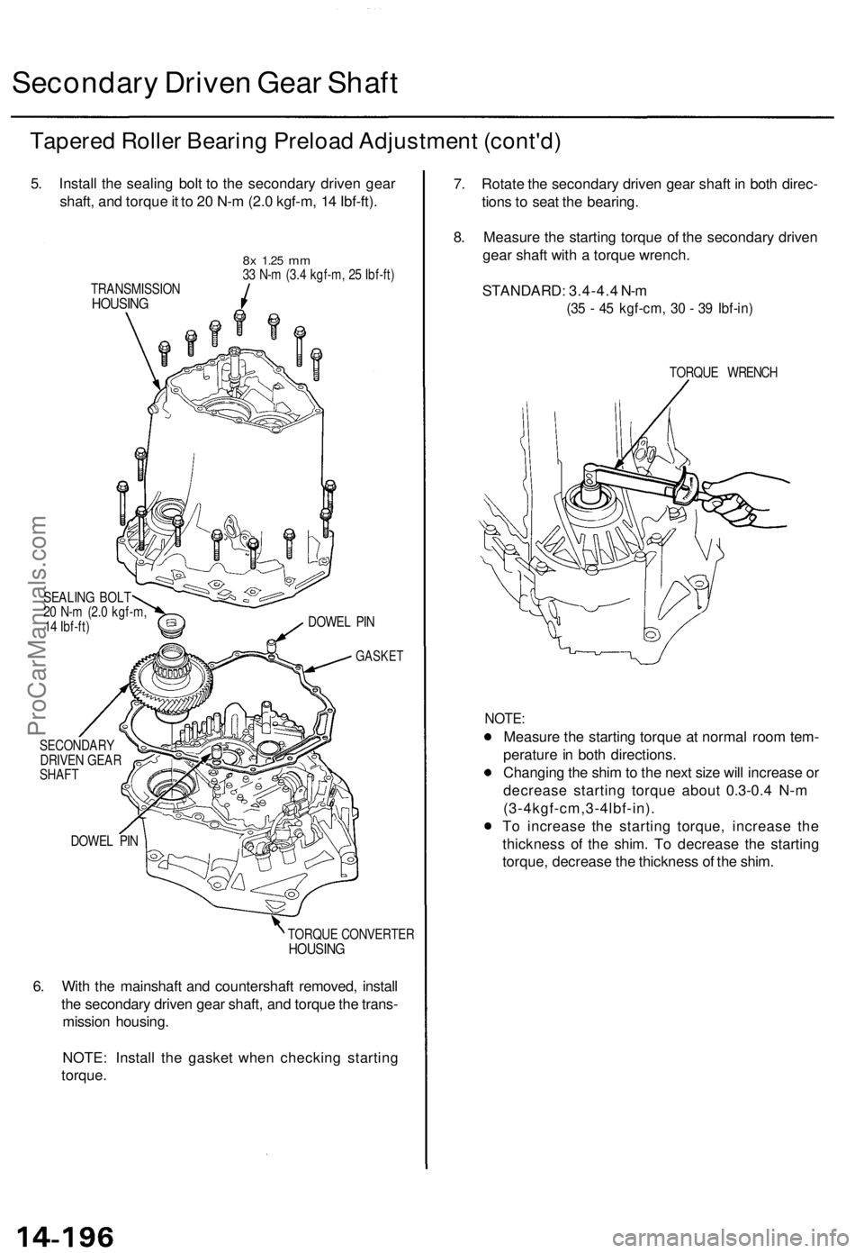
Secondary Drive n Gea r Shaf t
Tapere d Rolle r Bearin g Preloa d Adjustmen t (cont'd )
5. Instal l th e sealin g bol t t o th e secondar y drive n gea r
shaft , an d torqu e it t o 2 0 N- m (2. 0 kgf-m , 1 4 Ibf-ft) .
TRANSMISSIO NHOUSING
8x 1.2 5 mm33 N- m (3. 4 kgf-m , 2 5 Ibf-ft )
SEALIN G BOL T
2 0 N- m (2. 0 kgf-m ,
1 4 Ibf-ft ) DOWE
L PI N
GASKE T
SECONDAR Y
DRIVE N GEA R
SHAF T
DOWE L PI N
TORQUE CONVERTE R
HOUSING
6. Wit h th e mainshaf t an d countershaf t removed , instal l
th e secondar y drive n gea r shaft , an d torqu e th e trans -
missio n housing .
NOTE : Instal l th e gaske t whe n checkin g startin g
torque . 7
. Rotat e th e secondar y drive n gea r shaf t i n bot h direc -
tion s t o sea t th e bearing .
8 . Measur e th e startin g torqu e o f th e secondar y drive n
gea r shaf t wit h a torqu e wrench .
STANDARD : 3.4-4. 4 N- m
(35 - 4 5 kgf-cm , 3 0 - 3 9 Ibf-in )
TORQU E WRENC H
NOTE:
Measur e th e startin g torqu e a t norma l roo m tem -
peratur e in bot h directions .
Changin g th e shi m to th e nex t siz e wil l increas e o r
decreas e startin g torqu e abou t 0. 3-0. 4 N- m
(3-4kgf-cm,3-4lbf-in) .
T o increas e th e startin g torque , increas e th e
thicknes s o f th e shim . T o decreas e th e startin g
torque , decreas e th e thicknes s o f th e shim .
ProCarManuals.com
Page 410 of 1771
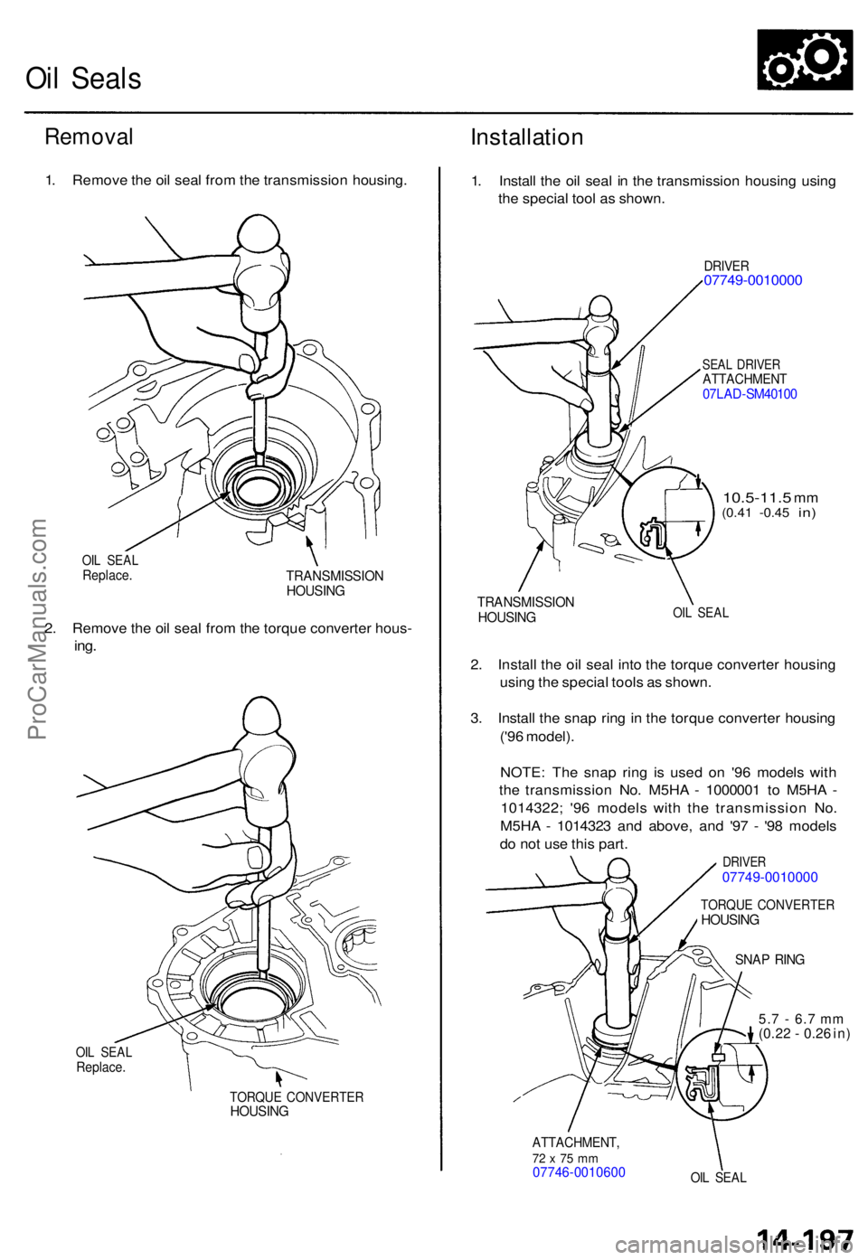
Oil Seal s
Remova l
1. Remov e th e oi l sea l fro m th e transmissio n housing .
OIL SEA LReplace .TRANSMISSIO NHOUSING
2. Remov e th e oi l sea l fro m th e torqu e converte r hous -
ing.
OIL SEA LReplace .
TORQUE CONVERTE RHOUSING
Installatio n
1. Instal l th e oi l sea l i n th e transmissio n housin g usin g
th e specia l too l a s shown .
DRIVER07749-001000 0
SEAL DRIVE RATTACHMEN T07LAD-SM4010 0
10.5-11. 5 mm(0.4 1 -0.4 5 in)
TRANSMISSIO NHOUSINGOIL SEA L
2. Instal l th e oi l sea l int o th e torqu e converte r housin g
usin g th e specia l tool s a s shown .
3 . Instal l th e sna p rin g in th e torqu e converte r housin g
('9 6 model) .
NOTE : Th e sna p rin g i s use d o n '9 6 model s wit h
th e transmissio n No . M5H A - 100000 1 t o M5H A -
1014322 ; '9 6 model s wit h th e transmissio n No .
M5H A - 101432 3 an d above , an d '9 7 - '9 8 model s
d o no t us e thi s part .
DRIVE R07749-0010000
TORQU E CONVERTE RHOUSING
SNAP RIN G
5.7 - 6. 7 m m(0.22 - 0.2 6 in )
ATTACHMENT ,72 x 75 m m07746-001060 0OIL SEA L
ProCarManuals.com
Page 411 of 1771
Torque Converte r Housin g Bearing s
Mainshaf t Bearing/Oi l Sea l Replacemen t
1. Driv e ou t o r pul l u p th e mainshaf t bearin g an d oi l sea l
usin g th e specia l tool s a s shown .
DRIVER07749-001000 0
TORQUE CONVERTE R HOUSIN G ATTACHMENT ,07947-6340500
SLIDE HAMMER , 3/8 " - 1 6
(Commerciall y available )
ADJUSTABL E
BEARIN G PULLER ,
25 - 4 0 m m07736-A01000 B o r0773 6-A01000 A
2. Driv e i n th e ne w mainshaf t bearin g unti l i t bottom s
i n th e housin g usin g th e specia l tool s a s shown .
DRIVER07749-001000 0
ATTACHMENT ,62 x 68 m m07746-001050 0
3. Instal l th e ne w oi l sea l flus h wit h th e housin g usin g
th e specia l tool s a s shown .
DRIVER07749-001000 0
ATTACHMENT ,72 x 7 5 m m07746-001060 0
ProCarManuals.com
Page 416 of 1771
A/T Gea r Positio n Switc h
Installatio n (cont'd )
3. Instal l th e A/ T gea r positio n switc h o n th e contro l
shaft, the n instal l th e bolt s loosely .
CONTRO L SHAF T
6 x 1.0 mm BOLTS
Tighte n loosely . A/
T GEA R POSITIO N
SWITC H
4. Instal l a ne w loc k washe r o n th e A/ T gea r positio n
switch b y alignin g it s projecte d ti p wit h th e posi -
tio n mar k o n th e A/ T gea r positio n switc h a s shown .
POSITIO N A/T GEAR POSITIO NMARK SWITC H
6x1.0 mm12 N- m (1. 2 kgf-m ,
8. 7 Ibf-ft )
LOC K TAB S
LEVE R
LOCKNU T
1 2 N- m (1. 2 kgf-m ,
8. 7 Ibf-ft ) CONTRO
L
SHAF T
5. Tighte n th e locknu t whil e holdin g th e deten t leve r i n
th e position , the n ben d th e loc k tab s agains t th e
locknut .
6 . Tighte n th e 6 m m bolt s t o th e specifie d torque .
ProCarManuals.com
Page 417 of 1771
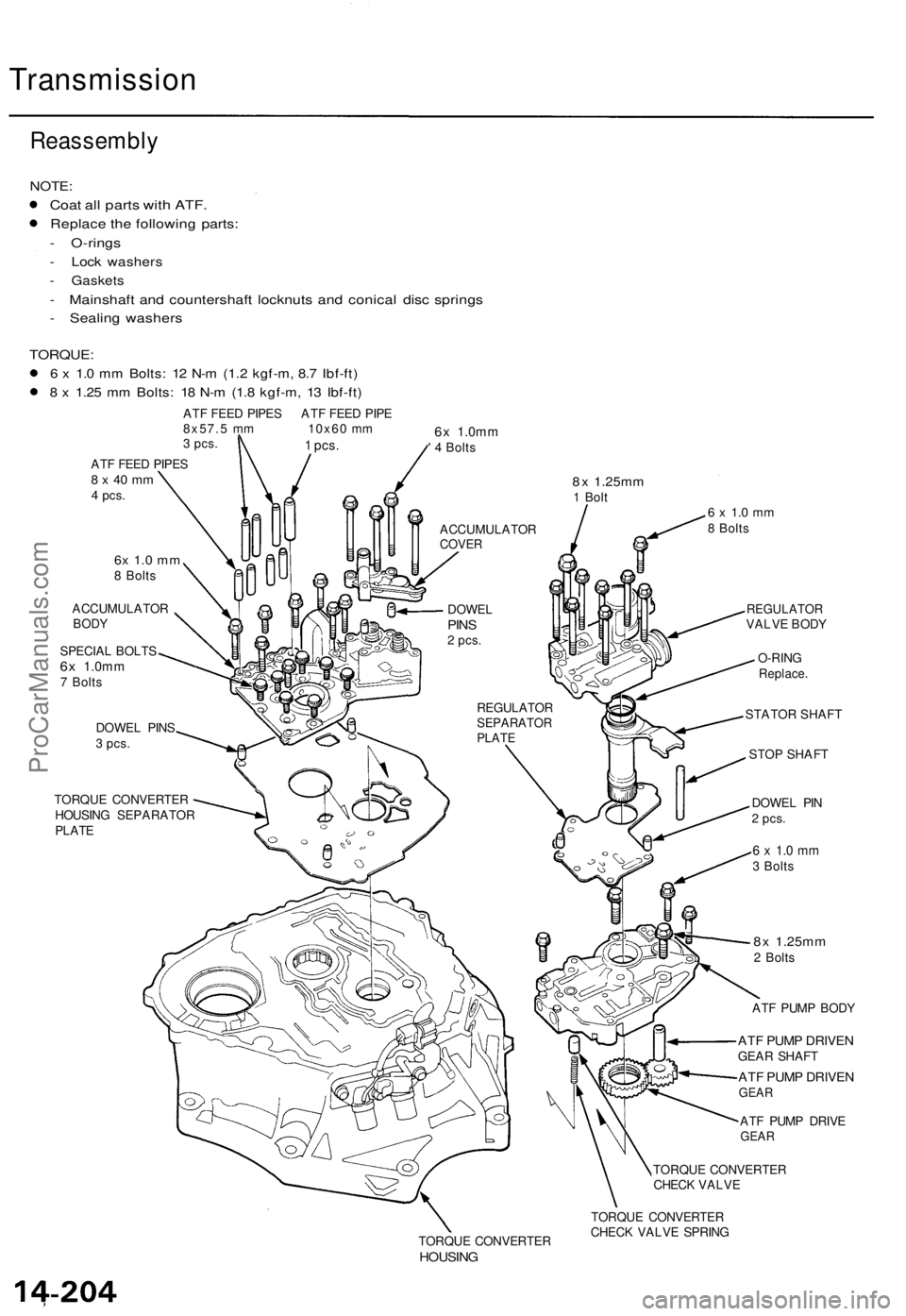
Transmission
Reassembly
NOTE:
Coat al l part s wit h ATF .
Replac e th e followin g parts :
- O-ring s
- Loc k washer s
- Gasket s
- Mainshaf t an d countershaf t locknut s an d conica l dis c spring s
- Sealin g washer s
TORQUE :
6 x 1. 0 m m Bolts : 1 2 N- m (1. 2 kgf-m , 8. 7 Ibf-ft )
8 x 1.2 5 m m Bolts : 1 8 N- m (1. 8 kgf-m , 1 3 Ibf-ft )
ATF FEE D PIPE S AT F FEE D PIP E
8x57. 5 m m 10x6 0 m m
3 pcs .
ATF FEE D PIPE S8 x 4 0 m m4 pcs .
6x 1. 0 m m8 Bolt s
ACCUMULATO R
BODY
SPECIA L BOLT S6x 1.0m m7 Bolt s
DOWE L PIN S
3 pcs.
TORQU E CONVERTE R
HOUSIN G SEPARATO R
PLATE
6x 1.0m m' 4 Bolt s
8x 1.25m m1 Bol t6 x 1. 0 m m8 Bolt s
REGULATO RSEPARATO RPLATE
REGULATO RVALVE BOD Y
O-RIN G
Replace .
STATOR SHAFT
STOP SHAFT
DOWE L PI N
2 pcs .
6 x 1. 0 m m3 Bolt s
8x 1.25m m2 Bolt s
AT F PUM P BOD Y
ATF PUM P DRIVE NGEAR SHAF T
ATF PUM P DRIVE NGEAR
ATF PUM P DRIV EGEAR
TORQU E CONVERTE R
CHEC K VALV E
TORQU E CONVERTE R
HOUSING
TORQUE CONVERTE R
CHEC K VALV E SPRIN G
1 pcs.
ACCUMULATO RCOVER
DOWE LPINS2 pcs .
ProCarManuals.com