Page 61 of 1771
Timing Bel t
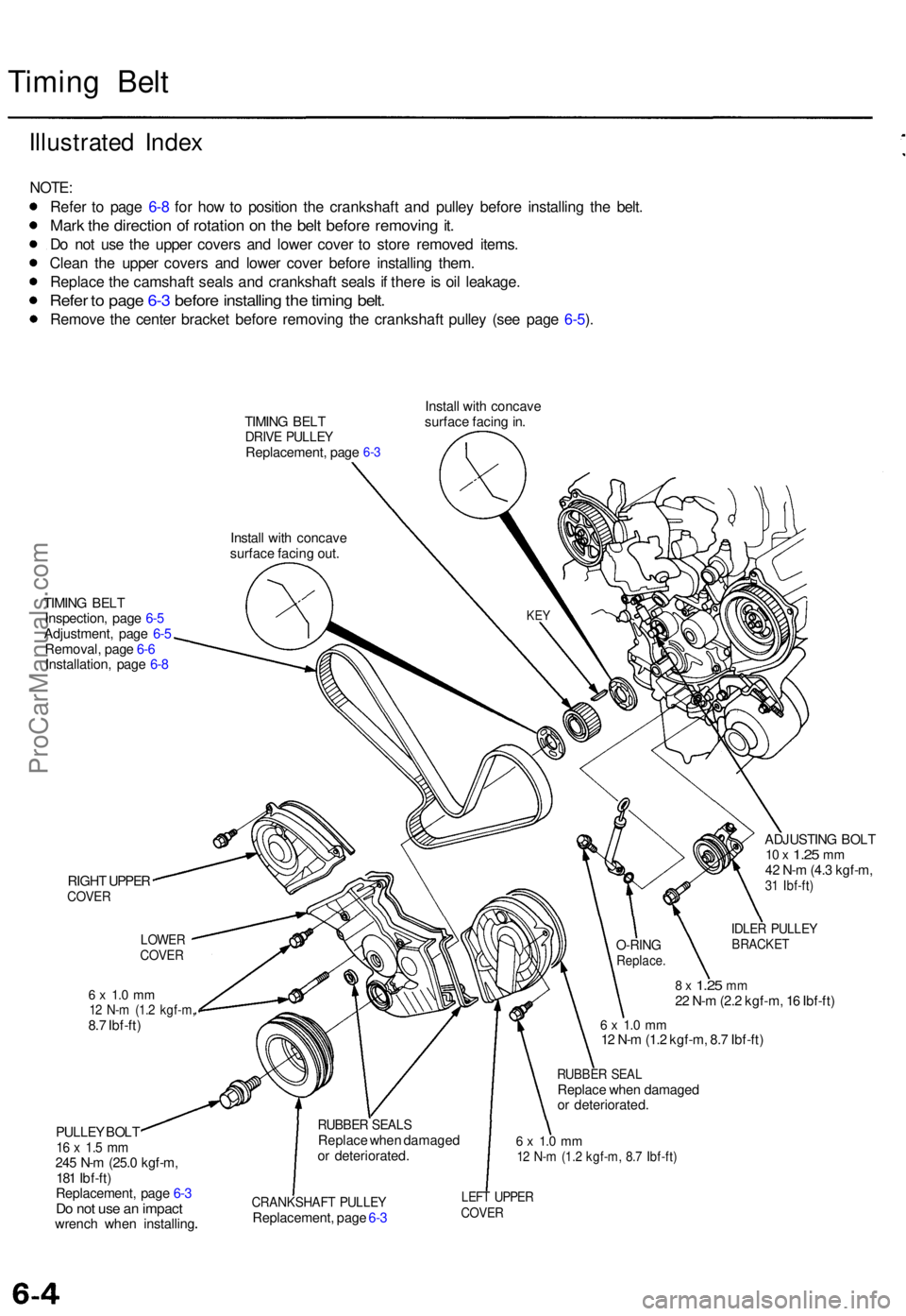
Illustrate d Inde x
NOTE :
Refe r t o pag e 6- 8 fo r ho w to positio n th e crankshaft and pulle y befor e installin g th e belt .
Mark th e directio n o f rotatio n o n th e bel t befor e removin g it .
Do no t us e th e uppe r cover s an d lowe r cove r t o stor e remove d items .
Clea n th e uppe r cover s an d lowe r cove r befor e installin g them .
Replac e th e camshaf t seal s an d crankshaf t seal s i f ther e is oi l leakage .
Refer t o pag e 6- 3 befor e installin g th e timin g belt .
Remov e th e cente r bracke t befor e removin g th e crankshaf t pulle y (se e pag e 6-5 ).
TIMIN G BEL TDRIV E PULLE YReplacement , pag e
Instal l wit h concav e
surfac e facin g out . Instal
l wit h concav e
surfac e facin g in .6-3
TIMIN G BEL T
Inspection , pag e 6- 5
Adjustment , pag e 6-5
Removal , pag e 6- 6
Installation , pag e 6- 8
RIGH T UPPE R
COVE R
6 x 1. 0 m m12 N- m (1. 2 kgf-m ,8.7 Ibf-ft )
PULLE Y BOL T
16 x 1. 5 m m245 N- m (25. 0 kgf-m ,
18 1 Ibf-ft )
Replacement , pag e 6- 3
Do no t us e a n impac twrench whe n installin g ADJUSTIN
G BOL T
10 x 1.2 5 mm42 N- m (4. 3 kgf-m ,31 Ibf-ft )
IDLER PULLE YBRACKE T
8 x 1.2 5 mm22 N- m (2. 2 kgf-m , 1 6 Ibf-ft )
6 x 1. 0 m m12 N- m (1. 2 kgf-m , 8. 7 Ibf-ft )
RUBBE R SEA LReplac e whe n damage d
o r deteriorated .
6 x 1. 0 m m12 N- m (1. 2 kgf-m , 8. 7 Ibf-ft )
CRANKSHAF T PULLE YReplacement , pag e 6- 3
LEF T UPPE RCOVER
RUBBE R SEAL SReplac e whe n damage d
o r deteriorated .
O-RINGReplace .
LOWERCOVER
KEY
ProCarManuals.com
Page 108 of 1771
Crankshaft
Inspection
Clean the crankshaft oil passages with pipe cleaners
or a suitable brush.
Check the keyway and threads.
Alignment
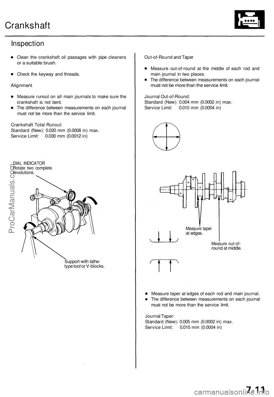
Measure runout on all main journals to make sure the
crankshaft is not bent.
The difference between measurements on each journal
must not be more than the service limit.
Crankshaft Total Runout:
Standard (New): 0.020 mm (0.0008 in) max.
Service Limit: 0.030 mm (0.0012 in)
DIAL INDICATOR
Rotate two complete
revolutions.
Support with lathe-
type tool or V-blocks.
Out-of-Round and Taper
Measure out-of-round at the middle of each rod and
main journal in two places.
The difference between measurements on each journal
must not be more than the service limit.
Journal Out-of-Round:
Standard (New): 0.004 mm (0.0002 in) max.
Service Limit: 0.010 mm (0.0004 in)
Measure out-of-
round at middle.
Measure taper at edges of each rod and main journal.
The difference between measurements on each journal
must not be more than the service limit.
Journal Taper:
Standard (New): 0.005 mm (0.0002 in) max.
Service Limit: 0.010 mm (0.0004 in)
Measure taper
at edges.ProCarManuals.com
Page 585 of 1771
Check for Wear and Damage
The starter should crank the engine smoothly and steadily.
If the starter engages, but cranks the engine erratically,
remove it, and inspect the starter drive gear and torque
converter ring gear for damage.
• Check the drive gear overrunning clutch for binding
or slipping when the armature is rotated with the
drive gear held. If the clutch is damaged, replace the
clutch assembly.
Check Cranking Voltage and Current Draw
Cranking voltage should be no less than 8.0 volts.
Current draw should be no more than 450 amperes.
If cranking voltage is too low, or current draw too high,
check for:
Dead or low battery
Open circuit in starter armature commutator segments
Starter armature dragging
Shorted armature winding
Excessive drag in engine
Check Cranking rpm
Engine speed during cranking should be above 100 rpm.
If speed is too low, check for:
Loose battery or starter terminals
Excessively worn starter brushes
Open circuit in commutator segments
Dirty or damaged helical spline or drive gear
Defective drive gear overrunning clutch
Check Starter Disengagement
With the shift lever in or , turn the ignition switch to
"START (III)", and release to "ON (II)". The starter drive
gear should disengage from the flywheel ring gear when
you release the key.
If the drive gear hangs upon the flywheel ring gear, check
for:
• Solenoid plunger and switch malfunction
• Dirty drive gear assembly or damaged overrunning
clutchProCarManuals.com
Page 621 of 1771
Power Doo r Lock s
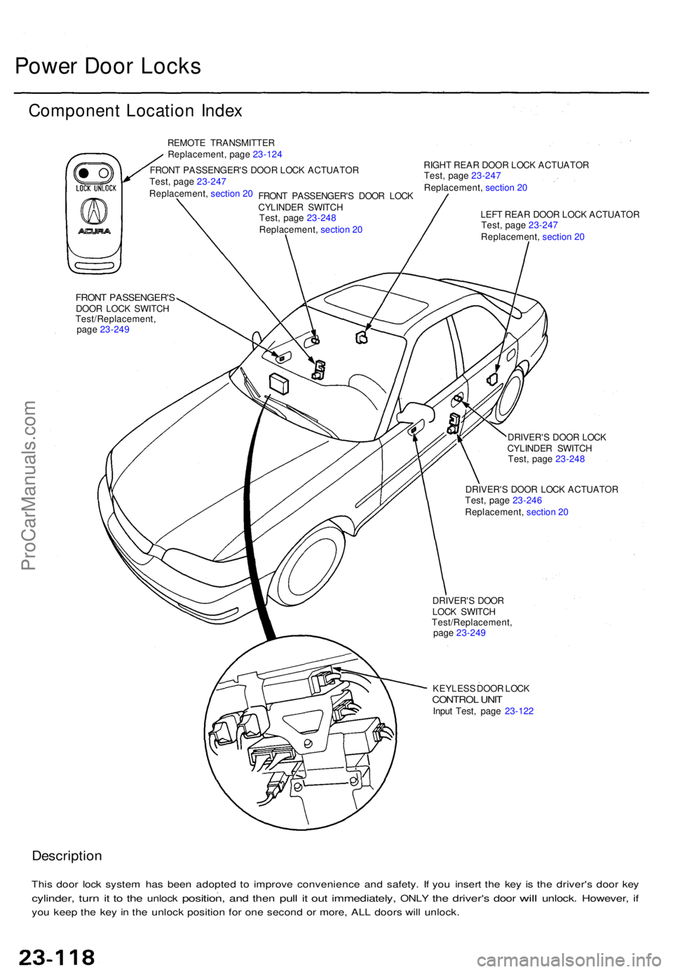
Componen t Locatio n Inde x
REMOT E TRANSMITTE R
Replacement , pag e 23-12 4
FRON T PASSENGER' S DOO R LOC K ACTUATO R RIGH
T REA R DOO R LOC K ACTUATO R
FRONT PASSENGER' SDOOR LOC K SWITC H
DRIVER'S DOO R LOC K
CYLINDE R SWITC H
DRIVER' S DOO R LOC K ACTUATO R
LEF
T REA R DOO R LOC K ACTUATO R
DRIVER' S DOO R
LOC K SWITC H
KEYLES S DOO R LOC K
CONTRO L UNI TInpu t Test , pag e 23-12 2
Descriptio n
This doo r loc k syste m ha s bee n adopte d t o improv e convenienc e an d safety . I f yo u inser t th e ke y i s th e driver' s doo r ke y
cylinder , turn it t o th e unloc k position , and the n pull it ou t immediately , ONLY the driver' s door will unlock . However , if
yo u kee p th e ke y i n th e unloc k positio n fo r on e secon d o r more , AL L door s wil l unlock .
FRONT PASSENGER' S DOO R LOC K
CYLINDE R SWITC H
Test
, pag e 23- 247
Replacement , section 20
Test /Replacement ,
pag e 23-24 9 Test
, pag e 23-24 8
Replacement , section 20 Test
, pag e 23-247
Replacement , section 20
Test , pag e 23-247
Replacement , section 20
Test , pag e 23-24 8
Test , pag e 23-24 6
Replacement , section 20
Test/Replacement ,
pag e 23-249
ProCarManuals.com
Page 622 of 1771
Troubleshooting
NOTE: Th e number s i n th e tabl e sho w th e troubleshootin g sequence .
CAUTION : T o preven t damag e to th e motor , appl y batter y voltag e onl y momentarily .
NOTE:
• Whe n th e remot e transmitte r butto n i s presse d th e firs t time , onl y th e driver' s doo r wil l unlock . Whe n th e butto n i s
presse d th e secon d time , al l th e door s wil l unlock .
• Th e door s wil l reloc k automaticall y afte r 2 0 second s i f a doo r i s no t opened , o r th e ke y i s ou t o f th e ignitio n switch .
• Th e keyles s entr y syste m wil l no t loc k th e door s whe n th e ke y i s i n th e ignitio n switch .
ProCarManuals.com
Page 742 of 1771
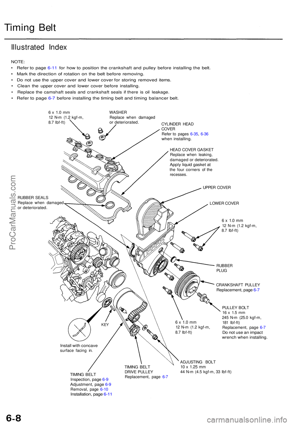
Timing Bel t
Illustrate d Inde x
NOTE :
• Refe r t o pag e 6-1 1 fo r ho w to positio n th e crankshaf t an d pulle y befor e installin g th e belt .
• Mar k th e directio n o f rotatio n o n th e bel t befor e removing .
• D o no t us e th e uppe r cove r an d lowe r cove r fo r storin g remove d items .
• Clea n th e uppe r cove r an d lowe r cove r befor e installing .
• Replac e th e camshaf t seal s an d crankshaf t seal s i f ther e i s oi l leakage .
• Refe r t o pag e 6- 7 befor e installin g th e timin g bel t an d timin g balance r belt .
6 x 1. 0 m m12 N- m (1. 2 kgf-m ,
8. 7 Ibf-ft ) WASHE
R
Replac e whe n damage dor deteriorated .CYLINDER HEA DCOVE RRefer t o page s 6-35 , 6-3 6whe n installing .
HEAD COVE R GASKE T
Replac e whe n leaking ,
damage d o r deteriorated .Apply liqui d gaske t a tth e fou r corner s o f th e
recesses .
RUBBE R SEAL S
Replac e whe n damage d
or deteriorated .
UPPER COVE R
LOWE R COVE R
6 x 1. 0 m m12 N- m (1. 2 kgf-m ,
8. 7 Ibf-ft )
RUBBE RPLUG
CRANKSHAF T PULLE Y
Replacement , pag e 6- 7
PULLE Y BOL T16 x 1. 5 m m245 N- m (25. 0 kgf-m ,
18 1 Ibf-ft )
Replacement , pag e 6- 7
Do no t us e a n impac twrench whe n installing .
Install wit h concav esurface facin g in .
TIMIN G BEL TInspection , pag e 6- 9Adjustment , pag e 6- 9Removal , pag e 6-1 0Installation , pag e 6-1 1
TIMIN G BEL TDRIV E PULLE Y
Replacement , pag e 6- 7 ADJUSTIN
G BOL T10 x 1.2 5 mm44 N- m (4. 5 kgf-m , 3 3 Ibf-ft )
KEY6 x 1. 0 m m12 N- m (1. 2 kgf-m ,
8. 7 Ibf-ft )
ProCarManuals.com
Page 745 of 1771
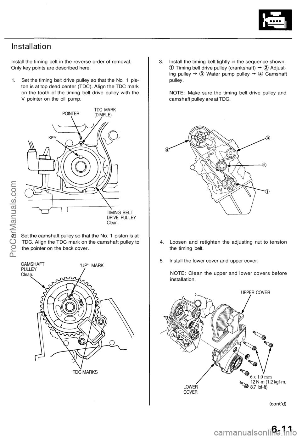
Installation
Install the timing belt in the reverse order of removal;
Only key points are described here.
1. Set the timing belt drive pulley so that the No. 1 pis-
ton is at top dead center (TDC). Align the TDC mark
on the tooth of the timing belt drive pulley with the
V pointer on the oil pump.
POINTER
TDC MARK
(DIMPLE)
TIMING BELT
DRIVE PULLEY
Clean.
2. Set the camshaft pulley so that the No. 1 piston is at
TDC. Align the TDC mark on the camshaft pulley to
the pointer on the back cover.
CAMSHAFT
PULLEY
Clean.
"UP" MARK
TDC MARKS
3. Install the timing belt tightly in the sequence shown.
Timing belt drive pulley (crankshaft) _ Adjust-
ing pulley Water pump pulley Camshaft
pulley.
NOTE: Make sure the timing belt drive pulley and
camshaft pulley are at TDC.
4. Loosen and retighten the adjusting nut to tension
the timing belt.
5. Install the lower cover and upper cover.
NOTE: Clean the upper and lower covers before
installation.
UPPER COVER
LOWER
COVER
6 x 1.0 mm
12 N-m (1.2 kgf-m,
8.7 Ibf-ft)
KEYProCarManuals.com
Page 748 of 1771
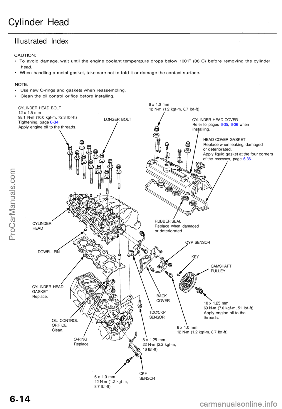
Cylinder Hea d
Illustrate d Inde x
CAUTION :
• T o avoi d damage , wai t unti l th e engin e coolan t temperatur e drop s belo w 100° F (3 8 C ) befor e removin g th e cylinde r
head.
• Whe n handlin g a meta l gasket , tak e car e no t t o fol d it o r damag e th e contac t surface .
NOTE:
• Us e ne w O-ring s an d gasket s whe n reassembling .
• Clea n th e oi l contro l orific e befor e installing .
CYLINDER HEA D BOL T12 x 1. 5 m m98. 1 N- m (10. 0 kgf-m , 72. 3 Ibf-ft )Tightening , pag e 6-3 4Appl y engin e oi l t o th e threads .
6 x 1. 0 m m12 N- m (1. 2 kgf-m , 8. 7 Ibf-ft )
LONGE R BOL T
CYLINDE R
HEA D
DOWE L PI N
CYLINDE R HEA D
GASKE T
Replace . CYLINDE
R HEA D COVE R
Refe r t o page s 6-35 , 6-3 6 whe n
installing .
HEAD COVE R GASKE TReplace whe n leaking , damage dor deteriorated .Apply liqui d gaske t a t th e fou r corner sof th e recesses , pag e 6-3 6
CAMSHAF T
PULLEY
OIL CONTRO L
ORIFIC E
Clean .
10 x 1.2 5 mm69 N- m (7. 0 kgf-m , 5 1 Ibf-ft )Apply engin e oi l t o th ethreads .
6 x 1. 0 m m12 N- m (1.2 kgf-m , 8. 7 Ibf-ft )
O-RIN G
Replac e
6 x 1. 0 m m12 N- m (1. 2 kgf-m ,
8. 7 Ibf-ft )
CKFSENSO R
8 x 1.2 5 mm22 N- m (2. 2 kgf-m ,
1 6 Ibf-ft )
TDC/CK
P
SENSO R
BACKCOVE R
CYP SENSO R
KEY
RUBBE R SEA L
Replac e whe n damage d
or deteriorated .
ProCarManuals.com