Page 770 of 1771
Camshaft/Rocker Arms and
Camshaft Seal
Installation
CAUTION:
• Make sure that all rockers are in alignment with their
valves when torquing the rocker assembly bolts.
• Valve locknuts should be loosened and adjusting
screws backed off before installation.
• To prevent the rocker arm assembly from coming
apart, leave the camshaft holder bolts in the holes.
1. After wiping down the camshaft and journals in the
cylinder head, lubricate both surfaces and install the
camshaft.
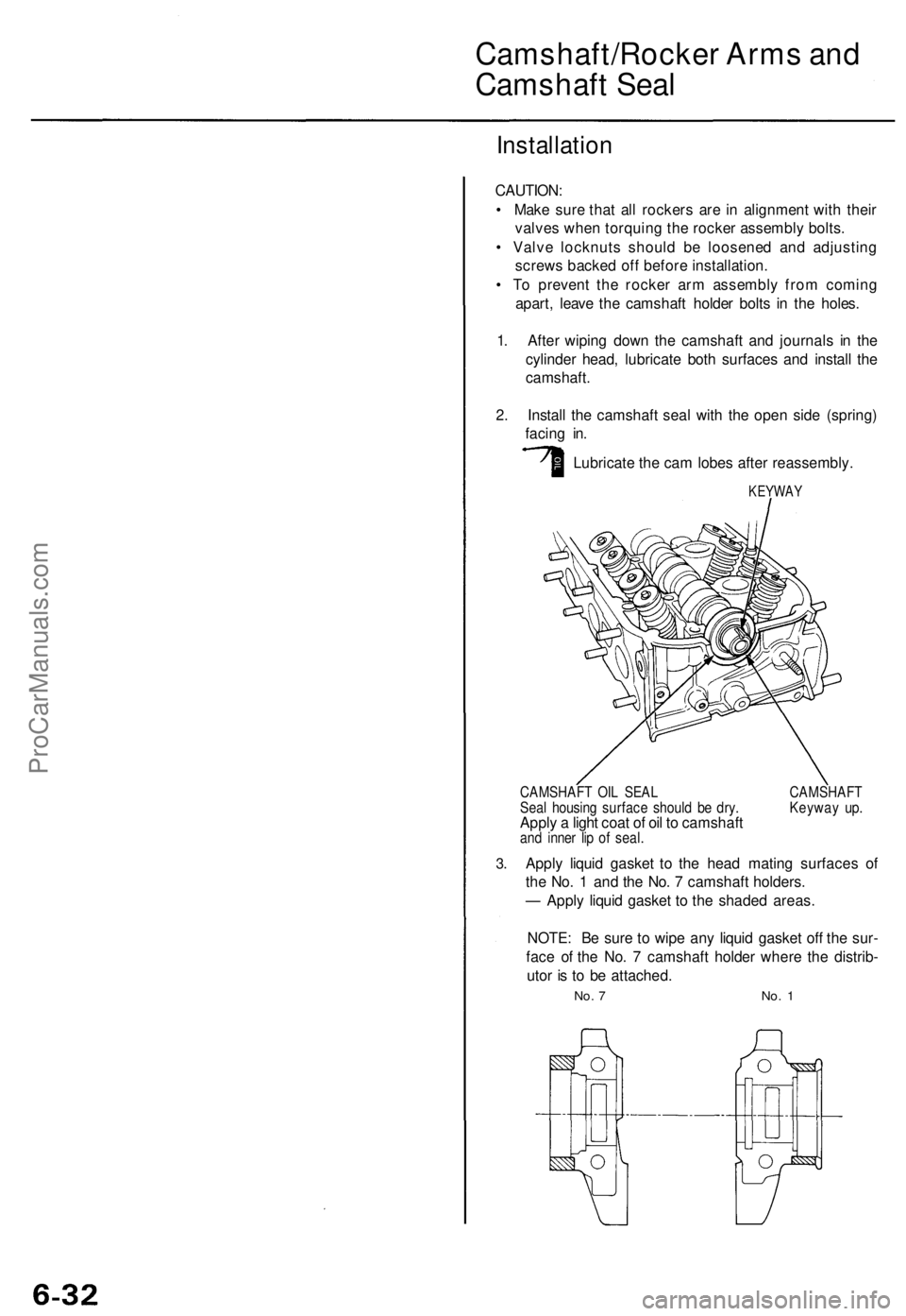
2. Install the camshaft seal with the open side (spring)
facing in.
Lubricate the cam lobes after reassembly.
KEYWAY
3.
CAMSHAFT OIL SEAL CAMSHAFT
Seal housing surface should be dry. Keyway up.
Apply a light coat of oil to camshaft
and inner lip of seal.
Apply liquid gasket to the head mating surfaces of
the No. 1 and the No. 7 camshaft holders.
— Apply liquid gasket to the shaded areas.
NOTE: Be sure to wipe any liquid gasket off the sur-
face of the No. 7 camshaft holder where the distrib-
utor is to be attached.
No. 7 No. 1ProCarManuals.com
Page 772 of 1771
Cylinder Hea d
Installatio n
Install th e cylinde r hea d in th e revers e orde r o f removal :
NOTE:
Alway s us e a ne w cylinde r hea d gasket .
Cylinde r hea d an d cylinde r bloc k surfac e mus t b e clean .
Tur n th e camshaf t s o th e keywa y i n facin g up .
Tur n th e crankshaft so th e No . 1 pisto n is a t TD C (se e
pag e 6-11 ).
Clea n th e oi l contro l orific e befor e installing .
D o no t us e th e uppe r cove r an d lowe r cove r fo r stor -
in g remove d item .
• Clea n th e uppe r cove r an d lowe r cove r befor e instal -
lation.
1. Alig n th e cylinde r hea d dowe l pins .
2 . Instal l th e oi l contro l orific e an d cylinde r hea d gas -
ket.
DOWE L PIN S
CYLINDE R HEA D
GASKE TReplace .
OIL CONTRO L
ORIFIC E
Clean .
O-RIN GReplace .
ProCarManuals.com
Page 773 of 1771
Cylinder Hea d
Installatio n (cont'd )
3. Tur n th e camshaf t unti l it s keywa y i s facin g u p (No . 1
pisto n TDC) .
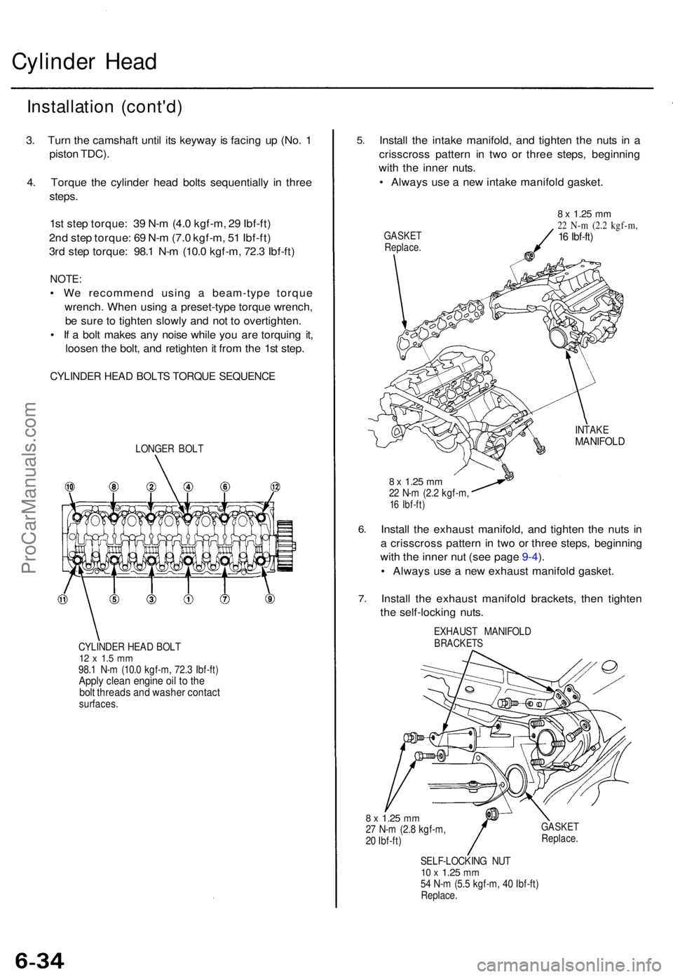
4 . Torqu e th e cylinde r hea d bolt s sequentiall y i n thre e
steps .
1s t ste p torque : 3 9 N- m (4. 0 kgf-m , 2 9 Ibf-ft )
2n d ste p torque : 6 9 N- m (7. 0 kgf-m , 5 1 Ibf-ft )
3r d ste p torque : 98. 1 N- m (10. 0 kgf-m , 72. 3 Ibf-ft )
NOTE :
• W e recommen d usin g a beam-typ e torqu e
wrench . Whe n usin g a preset-typ e torqu e wrench ,
b e sur e t o tighte n slowl y an d no t t o overtighten .
• I f a bol t make s an y nois e whil e yo u ar e torquin g it ,
loose n th e bolt , an d retighte n it fro m th e 1s t step .
CYLINDE R HEA D BOLT S TORQU E SEQUENC E
LONGER BOL T
CYLINDE R HEA D BOL T
12 x 1. 5 m m98. 1 N- m (10. 0 kgf-m , 72. 3 Ibf-ft )Apply clea n engin e oi l t o th ebol t thread s an d washe r contac tsurfaces .
5.
6.
7 .
Instal l th e intak e manifold , an d tighte n th e nut s i n a
crisscros s patter n i n tw o o r thre e steps , beginnin g
wit h th e inne r nuts .
• Alway s us e a ne w intak e manifol d gasket .
GASKE TReplace .
8 x 1.2 5 mm22 N- m (2. 2 kgf-m ,16 Ibf-ft )
INTAK EMANIFOL D
8 x 1.2 5 mm22 N- m (2. 2 kgf-m ,16 Ibf-ft )
Install th e exhaus t manifold , an d tighte n th e nut s i n
a crisscros s patter n in tw o o r thre e steps , beginnin g
wit h th e inne r nu t (se e pag e 9-4 ).
• Alway s us e a ne w exhaus t manifol d gasket .
Instal l th e exhaus t manifol d brackets , the n tighte n
th e self-lockin g nuts .
EXHAUS T MANIFOL DBRACKETS
8 x 1.2 5 mm27 N- m (2. 8 kgf-m ,
2 0 Ibf-ft )GASKE TReplace .
SELF-LOCKIN G NU T10 x 1.2 5 mm54 N- m (5. 5 kgf-m , 4 0 Ibf-ft )
Replace .
ProCarManuals.com
Page 774 of 1771
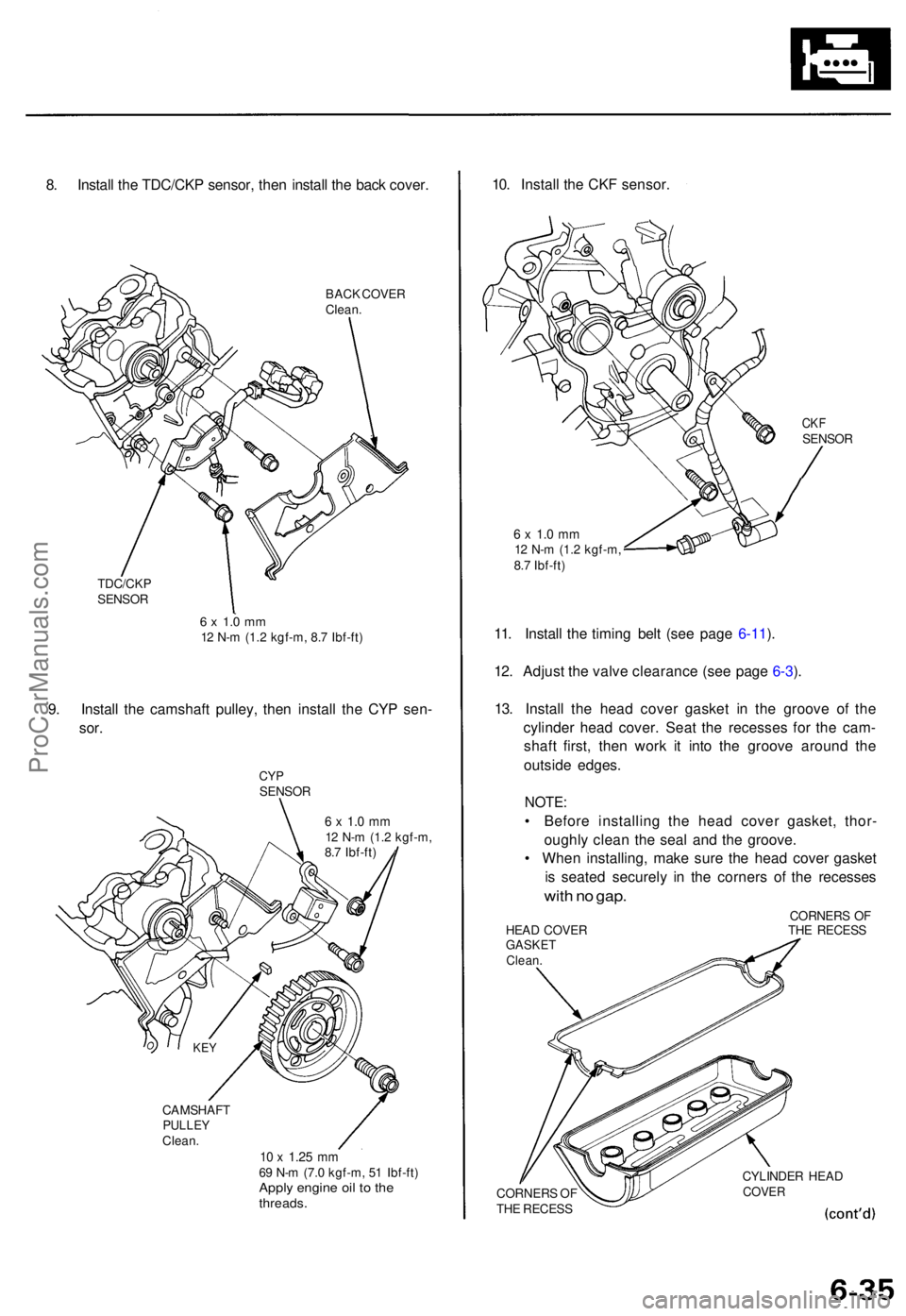
8. Instal l th e TDC/CK P sensor , the n instal l th e bac k cover .
BACK COVE R
Clean .
TDC/CK P
SENSO R
6 x 1. 0 m m12 N- m (1. 2 kgf-m , 8. 7 Ibf-ft )
9. Instal l th e camshaf t pulley , the n instal l th e CY P sen -
sor.
CY PSENSO R
6 x 1. 0 m m12 N- m (1. 2 kgf-m ,
8. 7 Ibf-ft )
CAMSHAF T
PULLEYClean.10 x 1.2 5 mm69 N- m (7. 0 kgf-m , 5 1 Ibf-ft )Apply engin e oi l t o th ethreads .
10. Instal l th e CK F sensor .
CKFSENSO R
6 x 1. 0 m m12 N- m (1. 2 kgf-m ,
8. 7 Ibf-ft )
11. Instal l th e timin g bel t (se e pag e 6-11 ).
12 . Adjus t th e valv e clearanc e (se e pag e 6-3 ).
13 . Instal l th e hea d cove r gaske t i n th e groov e o f th e
cylinde r hea d cover . Sea t th e recesse s fo r th e cam -
shaf t first , the n wor k i t int o th e groov e aroun d th e
outsid e edges .
NOTE:
• Befor e installin g th e hea d cove r gasket , thor -
oughl y clea n th e sea l an d th e groove .
• Whe n installing , mak e sur e th e hea d cove r gaske t
i s seate d securel y i n th e corner s o f th e recesse s
with n o gap .
CORNER S O F
HEA D COVE R TH E RECES S
GASKETClean.
CORNER S O F
TH E RECES S CYLINDE
R HEA DCOVE R
KEY
ProCarManuals.com
Page 788 of 1771
Crankshaft
Inspection
• Clean the crankshaf t oi l passage s wit h pip e cleaner s
or a suitabl e brush .
• Chec k th e keywa y an d threads .
Alignmen t
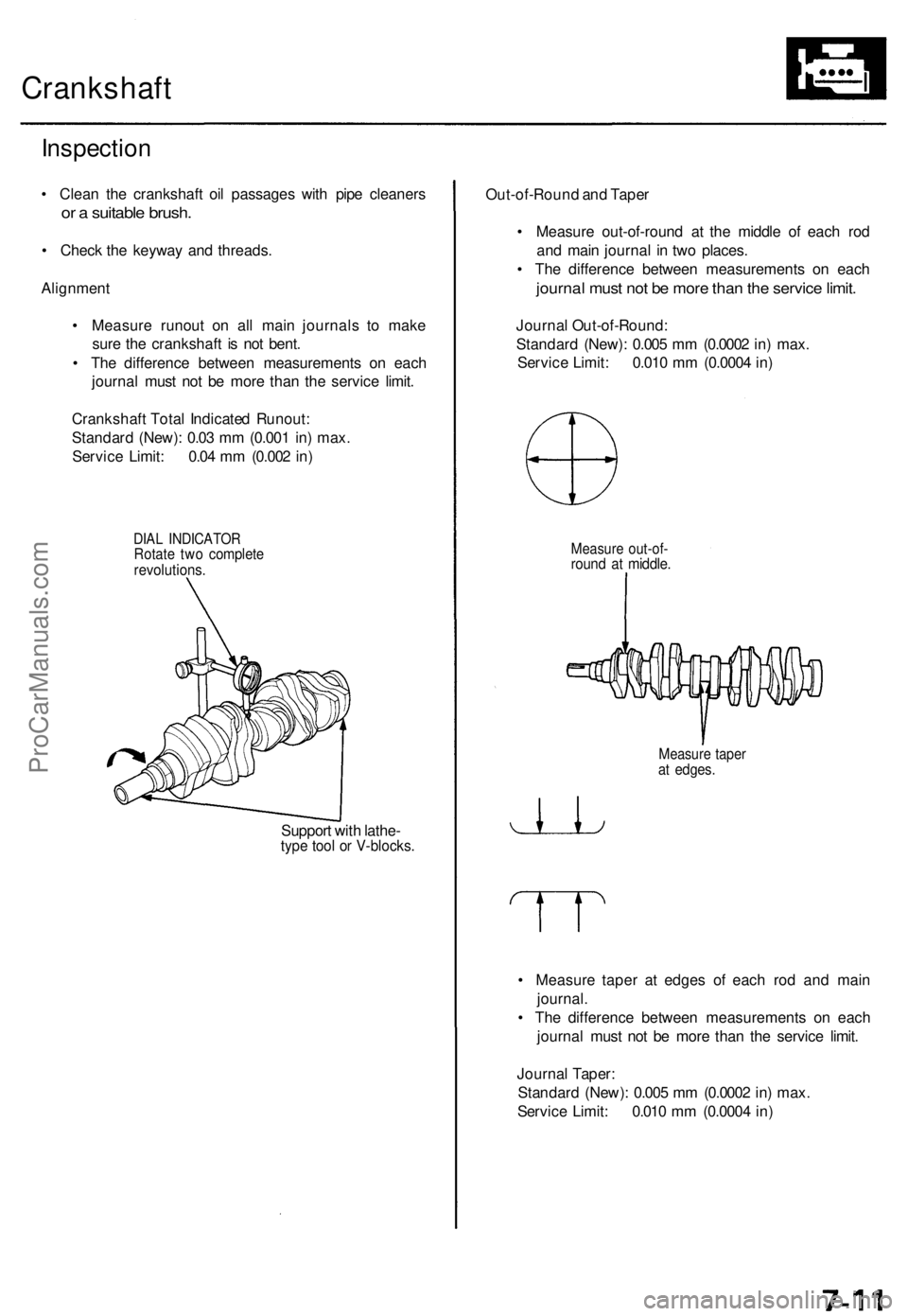
• Measur e runou t o n al l mai n journal s t o mak e
sur e th e crankshaf t i s no t bent .
• Th e differenc e betwee n measurement s o n eac h
journa l mus t no t b e mor e tha n th e servic e limit .
Crankshaf t Tota l Indicate d Runout :
Standar d (New) : 0.0 3 m m (0.00 1 in ) max .
Servic e Limit : 0.0 4 m m (0.00 2 in )
DIA L INDICATO RRotate tw o complet erevolutions .
Support wit h lathe -type too l o r V-blocks .
Out-of-Roun d an d Tape r
• Measur e out-of-roun d a t th e middl e o f eac h ro d
an d mai n journa l i n tw o places .
• Th e differenc e betwee n measurement s o n eac h
journa l mus t no t b e mor e tha n th e servic e limit .
Journa l Out-of-Round :
Standar d (New) : 0.00 5 m m (0.000 2 in ) max .
Servic e Limit : 0.01 0 m m (0.000 4 in )
Measur e out-of -round a t middle .
Measur e tape rat edges .
• Measur e tape r a t edge s o f eac h ro d an d mai n
journal .
• Th e differenc e betwee n measurement s o n eac h
journa l mus t no t b e mor e tha n th e servic e limit .
Journa l Taper :
Standar d (New) : 0.00 5 m m (0.000 2 in ) max .
Servic e Limit : 0.01 0 m m (0.000 4 in )
ProCarManuals.com
Page 1538 of 1771
Five-step Troubleshooting
1. Verify The Complaint
Turn on all the components in the problem circuit to
verify the customer complaint. Note the symptoms.
Do not begin disassembly or testing until you have
narrowed down the problem area.
2. Analyze The Schematic
Look up the schematic for the problem circuit.
Determine how the circuit is supposed to work by
tracing the current paths from the power feed
through the circuit components to ground. If several
circuits fail at the same time, the fuse or ground is a
likely cause.
Based on the symptoms and your understanding of
the circuit operation, identify one or more possible
causes of the problem.
3. Isolate The Problem By Testing The Circuit
Make circuit tests to check the diagnosis you made
in step 2. Keep in mind that a logical, simple proce-
dure is the key to efficient troubleshooting. Test for
the most likely cause of failure first. Try to make
tests at points that are easily accessible.
4. Fix The Problem
Once the specific problem is identified, make the
repair. Be sure to use proper tools and safe proce-
dures.
5. Make Sure The Circuit Works
Turn on all components in the repaired circuit in all
modes to make sure you've fixed the entire prob-
lem. If the problem was a blown fuse, be sure to
test all of the circuits on the fuse. Make sure no new
problems turn up and the original problem does not
recur.
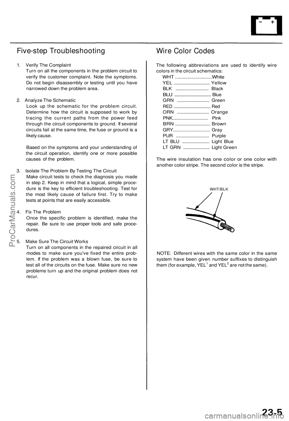
Wire Color Codes
The following abbreviations are used to identify wire
colors in the circuit schematics:
WHT .............................White
YEL ............................... Yellow
BLK .............................. Black
BLU
..............................
Blue
GRN ............................. Green
RED
..............................
Red
ORN ............................. Orange
PNK.............................. Pink
BRN .............................. Brown
GRY.............................. Gray
PUR .............................. Purple
LT BLU ......................... Light Blue
LT GRN ........................ Light Green
The wire insulation has one color or one color with
another color stripe. The second color is the stripe.
WHT/BLK
NOTE: Different wires with the same color in the same
system have been given number suffixes to distinguish
them (for example, YEL1 and YEL2 are not the same).ProCarManuals.com
Page 1543 of 1771
CLIMATE CONTROL UNIT
RADIATOR
FAN CONTROL
MODULE
ABS CONTROL UNIT
('95 -97 models)
KEYLESS DOOR LOCK CONTROL
UNIT ('98 model)
SECURITY CONTROL
UNIT
ABS CONTROL UNIT
('98 model)
MOONROOF OPEN RELAY
Wire colors: GRY, GRN/YEL,
GRN,
YEL and BLK
MOONROOF CLOSE RELAY
Wire colors: GRY/RED, GRN/RED,
GRN,
YEL and BLK
TRANSMISSION
CONTROL
MODULE (TCM)ProCarManuals.com
Page 1553 of 1771
Ignition Switch
Steering Lock Replacement (cont'd)
6. Remove the column holder mounting bolts and nuts.
16 N-m
(1.6 kgf-m, 12 Ibf-ft)
COLUMN
HOLDER
38 N-m
(3.9 kgf-m, 28 Ibf-ft)
7. Lower the steering column assembly.
8. Center-punch each of the two shear bolts, and drill
their heads off with a 5 mm (3/16 in) drill bit.
CAUTION: Do not damage the switch body when
removing the shear bolts.
9. Remove the shear bolts from the switch body, then
remove the steering lock assembly.
Installation:
1. Install the new ignition switch without the key
inserted.
2. Loosely tighten the new shear bolts.
3. Insert the ignition key, and check for proper opera-
tion of the steering wheel lock and that the ignition
key turns freely.
4. Tighten the shear bolts until the hex heads twist off.
SHEAR BOLT
TWIST-OFF PORTION
5. Install in the reverse order of removal.
6. Enter the anti-theft code for the radio, then enter the
customer's radio station presets.ProCarManuals.com