Page 1557 of 1771
Check for Wear and Damage
The starter should crank the engine smoothly and steadily.
If the starter engages, but cranks the engine erratically,
remove it, and inspect the starter drive gear and torque
converter ring gear for damage.
Check the drive gear overrunning clutch for binding or
slipping when the armature is rotated with the drive
gear held. If the clutch is damaged, replace the clutch
assembly.
Check Cranking Voltage and Current Draw
Cranking voltage should be no less than 8.5 volts.
Current draw should be no more than 380 amperes.
If cranking voltage is too low, or current draw too high,
check for:
Dead or low battery
Open circuit in starter armature commutator segments
Starter armature dragging
Shorted armature winding
Excessive drag in engine
Check Cranking rpm
Engine speed during cranking should be above 100 rpm.
If speed is too low, check for:
Loose battery or starter terminals
Excessively worn starter brushes
Open circuit in commutator segments
Dirty or damaged helical spline or drive gear
Defective drive gear overrunning clutch
Check Starter Disengagement
With the shift lever in turn the ignition switch to
"START (III)", and release to "ON (II)". The starter drive
gear should disengage from the drive plate/ring gear
when you release the key.
If the drive gear hangs up on the drive plate/ring gear,
check for:
• Solenoid plunger and switch malfunction
• Dirty drive gear assembly or damaged overrunning
clutchProCarManuals.com
Page 1607 of 1771
Description
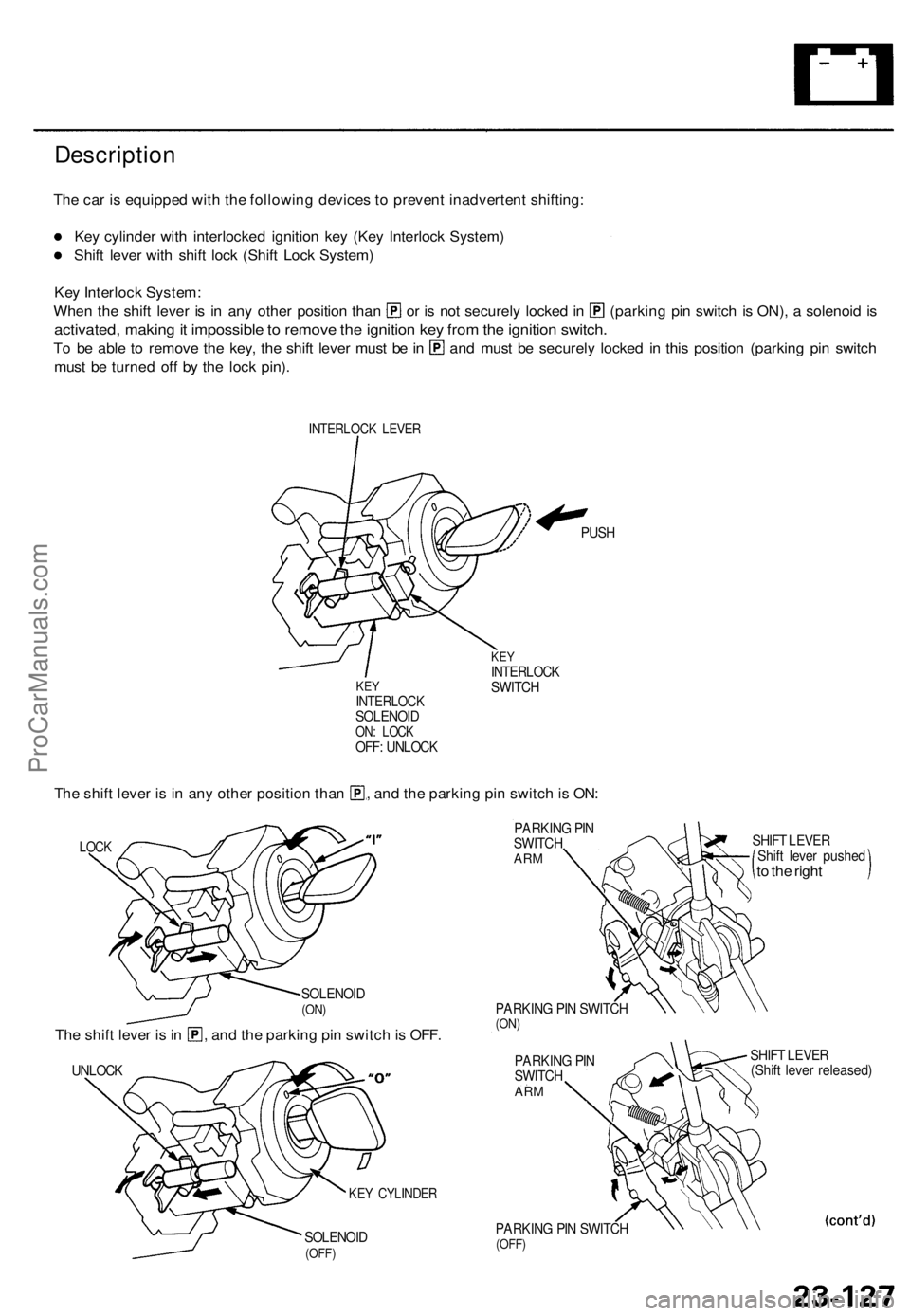
The car is equipped with the following devices to prevent inadvertent shifting:
Key cylinder with interlocked ignition key (Key Interlock System)
Shift lever with shift lock (Shift Lock System)
Key Interlock System:
When the shift lever is in any other position than or is not securely locked in (parking pin switch is ON), a solenoid is
activated, making it impossible to remove the ignition key from the ignition switch.
To be able to remove the key, the shift lever must be in and must be securely locked in this position (parking pin switch
must be turned off by the lock pin).
INTERLOCK LEVER
KEY
INTERLOCK
SOLENOID
ON: LOCK
OFF: UNLOCK
PUSH
KEY
INTERLOCK
SWITCH
The shift lever is in any other position than , and the parking pin switch is ON:
LOCK
SOLENOID
(ON)
The shift lever is in , and the parking pin switch is OFF.
UNLOCK
SOLENOID
(OFF)
PARKING PIN
SWITCH
ARM
PARKING PIN SWITCH
(ON)
PARKING PIN
SWITCH
ARM
PARKING PIN SWITCH
(OFF)
SHIFT LEVER
Shift lever pushed
to the right
SHIFT LEVER
(Shift lever released)
KEY CYLINDERProCarManuals.com
Page 1608 of 1771
Interlock System
Description (cont'd)
Shift Lock System:
The shift lock system prevents the shift lever from moving to another position than [P] unless you step on the brake pedal
and the accelerator is in its rest position.
NOTE:
The shift lever cannot be shifted when the brake pedal and the accelerator are depressed at the same time.
In case of system malfunction, the shift lever can be released by pushing a key into the release slot near the shift lever.
SHIFT LEVER
SHIFT LEVER
SHIFT LOCK SOLENOID
(OFF: LOCK)
SHIFT LOCK SOLENOID
(ON: UNLOCK)
SHIFT LOCK STOP LEVER
SHIFT LOCK STOP LEVER
KEY
RELEASE LEVER
SHIFT LOCK STOP LEVERProCarManuals.com
Page 1611 of 1771
Interlock Syste m
Key Interloc k Solenoi d Tes t
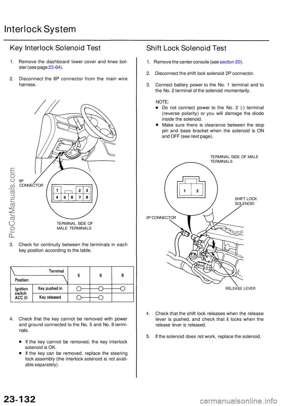
1. Remov e th e dashboar d lowe r cove r an d kne e bol -
ste r (se e pag e 23-64 ).
2 . Disconnec t th e 8 P connecto r fro m th e mai n wir e
harness .
TERMINA L SID E O F
MAL E TERMINAL S
3. Chec k fo r continuit y betwee n th e terminal s i n eac h
ke y positio n accordin g to th e table .
4 . Chec k tha t th e ke y canno t b e remove d wit h powe r
an d groun d connecte d t o th e No . 5 an d No . 8 termi -
nals.
If th e ke y canno t b e removed , th e ke y interloc k
solenoi d is OK .
I f th e ke y ca n b e removed , replac e th e steerin g
loc k assembl y (th e interloc k solenoi d is no t avail -
able separately) .
Shift Loc k Solenoi d Tes t
1. Remov e th e cente r consol e (se e sectio n 20 ).
2 . Disconnec t th e shif t loc k solenoi d 2 P connector .
3 . Connec t batter y powe r t o th e No . 1 termina l an d t o
th e No . 2 termina l o f th e solenoi d momentarily .
NOTE:
Do no t connec t powe r t o th e No . 2 (- ) termina l
(revers e polarity ) o r yo u wil l damag e th e diod e
insid e th e solenoid .
Mak e sur e ther e i s clearanc e betwee n th e sto p
pi n an d bas e bracke t whe n th e solenoi d i s O N
an d OF F (se e nex t page) .
TERMINA L SID E O F MAL E
TERMINAL S
2 P CONNECTO R SHIF
T LOC K
SOLENOI D
4.
RELEAS E LEVE R
Check tha t th e shif t loc k release s whe n th e releas e
leve r i s pushed , an d chec k tha t i t lock s whe n th e
releas e leve r i s released .
5. I f th e solenoi d doe s no t work , replac e th e solenoid .
8PCONNECTO R
ProCarManuals.com
Page 1626 of 1771
Integrated Control Unit
Input Test (cont'd)
Seat Belt Reminder and Key-in Warning System:
WIRE SIDE OF FEMALE TERMINALS
*: '97 - 98 models
Trml Wire
Test condition
Test: Desired result
Possible cause if result is not obtained
Power Window Key-off Timer System:
Trml Wire
Test condition
Test: Desired result
Possible cause if result is not obtainedProCarManuals.com
Page 1628 of 1771
Key-in Reminde r Syste m
Entry Ligh t Time r Syste m
Ignition Ke y Switc h Tes t
SRS component s ar e locate d in thi s area . Revie w th e SR S
componen t locations , precautions , an d procedure s i n th e
SR S (sectio n 24 ) befor e performin g repair s o r service .
NOTE : Refe r t o pag e 23-152 for the input test of
the beepe r circuit.
Whe n th e ignitio n ke y i s no t removed , th e key-i n beepe r
i n th e integrate d contro l uni t sense s groun d throug h th e
close d ignitio n ke y switch . Whe n yo u ope n th e driver' s
door, th e beepe r circui t sense s groun d throug h th e
close d doo r switch . Wit h groun d a t th e "BLU/WHT2" an d
"A13 " terminals , th e beepe r sounds .
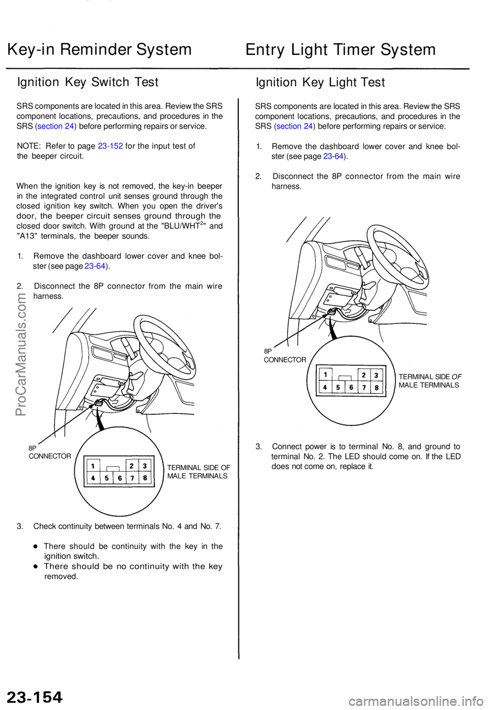
1 . Remov e th e dashboar d lowe r cove r an d kne e bol -
ste r (se e pag e 23-64 ).
2 . Disconnec t th e 8 P connecto r fro m th e mai n wir e
harness .
8PCONNECTO R
TERMINAL SID E O F
MAL E TERMINAL S
3. Chec k continuit y betwee n terminal s No . 4 an d No . 7 .
Ther e shoul d b e continuit y wit h th e ke y i n th e
ignitio n switch .
There shoul d b e n o continuit y wit h th e ke y
removed .
Ignition Ke y Ligh t Tes t
SRS component s ar e locate d in thi s area . Revie w th e SR S
componen t locations , precautions , an d procedure s i n th e
SR S (sectio n 24 ) befor e performin g repair s o r service .
1 . Remov e th e dashboar d lowe r cove r an d kne e bol -
ste r (se e pag e 23-64 ).
2 . Disconnec t th e 8 P connecto r fro m th e mai n wir e
harness .
8PCONNECTO R
TERMINAL SID E OF
MAL E TERMINAL S
3. Connec t powe r i s t o termina l No . 8 , an d groun d t o
termina l No . 2 . Th e LE D shoul d com e on . I f th e LE D
doe s no t com e on , replac e it .
ProCarManuals.com
Page 1686 of 1771
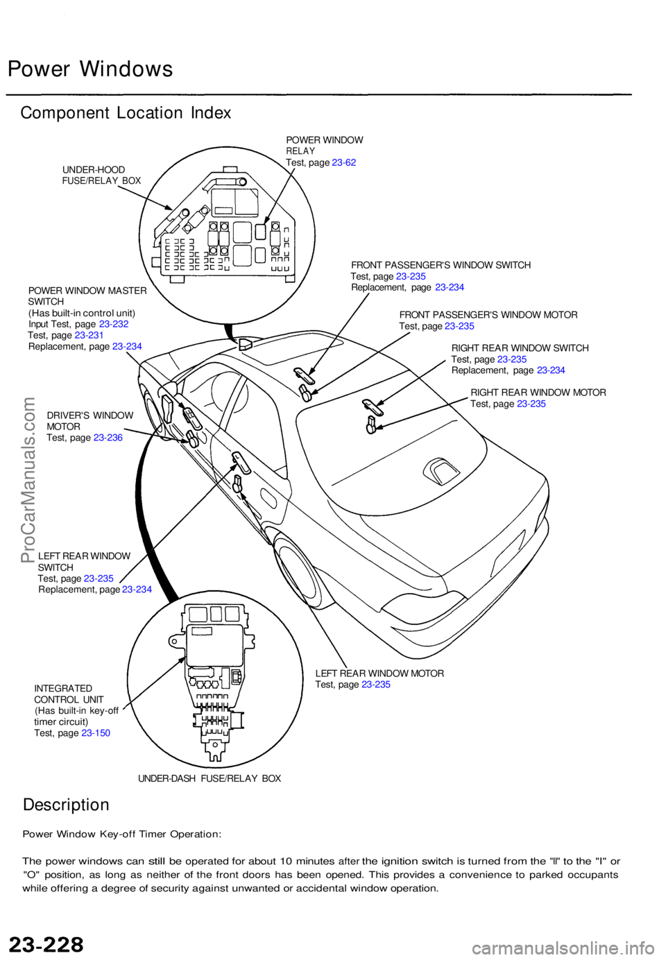
Power Window s
Componen t Locatio n Inde x
UNDER-HOO DFUSE/RELAY BO X
POWE R WINDO WRELAYTest, pag e 23-6 2
POWE R WINDO W MASTE R
SWITC H
(Has built-i n contro l unit )Input Test , pag e 23-23 2
Test , pag e 23-23 1
Replacement , pag e 23-23 4
DRIVER' S WINDO W
MOTO R
Test , pag e 23-23 6 FRON
T PASSENGER' S WINDO W SWITC H
Test , pag e 23-23 5
Replacement , pag e 23-23 4
FRON T PASSENGER' S WINDO W MOTO R
Test , pag e 23-23 5
RIGH T REA R WINDO W SWITC H
Test , pag e 23-23 5
Replacement , pag e 23-23 4
RIGH T REA R WINDO W MOTO R
Test , pag e 23-23 5
LEF T REA R WINDO W
SWITC H
Test , pag e 23-23 5
Replacement , pag e 23-23 4
LEFT REA R WINDO W MOTO R
Test , pag e 23-23 5
INTEGRATE DCONTROL UNI T
(Ha s built-i n key-of f
timer circuit )Test, pag e 23-150
UNDER-DASH FUSE/RELA Y BO X
Descriptio n
Power Windo w Key-of f Time r Operation :
The powe r window s can stil l be operate d for abou t 10 minute s after the ignitio n switch is turne d from the "II " to th e "I " o r
"O " position , a s lon g a s neithe r o f th e fron t door s ha s bee n opened . Thi s provide s a convenienc e t o parke d occupant s
while offerin g a degre e o f securit y agains t unwante d o r accidenta l windo w operation .
ProCarManuals.com
Page 1694 of 1771
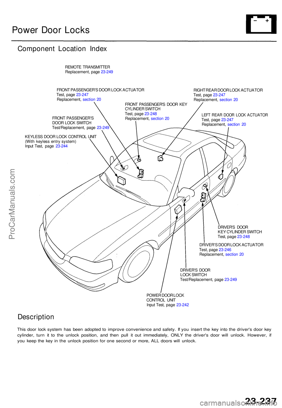
Power Doo r Lock s
Componen t Locatio n Inde x
REMOT E TRANSMITTE R
Replacement , pag e 23-24 9
RIGHT REA R DOO R LOC K ACTUATO R
Test , pag e 23-24 7
Replacement , sectio n 2 0
LEF T REA R DOO R LOC K ACTUATO RTest, pag e 23-24 7
Replacement , sectio n 2 0
KEYLES S DOO R LOC K CONTRO L UNI T
(Wit h keyles s entr y system )
Inpu t Test , pag e 23-24 4
DRIVER'S DOO R
KE Y CYLINDE R SWITC H
Test , pag e 23-24 8
DRIVER' S DOO R LOC K ACTUATO R
Test , pag e 23-24 6
Replacement , sectio n 2 0
DRIVER' S DOO R
LOC K SWITC H
Test/Replacement , pag e 23-24 9
POWE R DOO R LOC K
CONTRO L UNI T
Inpu t Test , pag e 23-24 2
Descriptio n
This doo r loc k syste m ha s bee n adopte d t o improv e convenienc e an d safety . I f yo u inser t th e ke y int o th e driver' s doo r ke y
cylinder , tur n i t t o th e unloc k position , an d the n pul l i t ou t immediately , ONL Y th e driver' s doo r wil l unlock . However , i f
yo u kee p th e ke y i n th e unloc k positio n fo r on e secon d o r more , AL L door s wil l unlock .
FRONT PASSENGER' S DOO R LOC K ACTUATO R
Test , pag e 23-24 7
Replacement , sectio n 2 0
FRONT PASSENGER' S DOO R KE Y
CYLINDE R SWITC H
Test , pag e 23-24 8
Replacement , sectio n 2 0
FRON
T PASSENGER' S
DOO R LOC K SWITC H
Test/Replacement , pag e 23-24 9
ProCarManuals.com