1995 ACURA TL width
[x] Cancel search: widthPage 89 of 1771
Valve Seat s
Reconditionin g
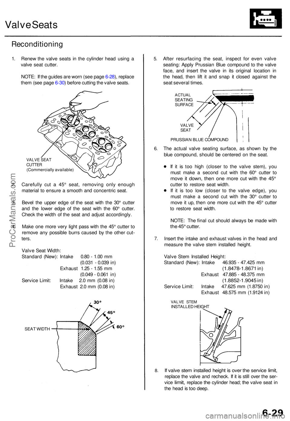
1. Rene w th e valv e seat s i n th e cylinde r hea d usin g a
valv e sea t cutter .
NOTE : I f th e guide s ar e wor n (se e pag e 6-28 ), replac e
the m (se e pag e 6-30 ) befor e cuttin g th e valv e seats .
2.
3.
4 .
VALV E SEA TCUTTE R(Commerciall y available )
Carefully cu t a 45 ° seat , removin g onl y enoug h
materia l t o ensur e a smoot h an d concentri c seat .
Beve l th e uppe r edg e o f th e sea t wit h th e 30 ° cutte r
an d th e lowe r edg e o f th e sea t wit h th e 60 ° cutter .
Chec k th e widt h o f th e sea t an d adjus t accordingly .
Mak e on e mor e ver y ligh t pas s wit h th e 45 ° cutte r t o
remov e an y possibl e burr s cause d b y th e othe r cut -
ters .
Valv e Sea t Width :
Standar d (New) : Intak e 0.8 0 - 1.0 0 m m
(0.03 1 - 0.03 9 in )
Exhaus t 1.2 5 - 1.5 5 m m
(0.04 9 - 0.06 1 in )
Servic e Limit : Intak e 2. 0 m m (0.0 8 in )
Exhaus t 2. 0 m m (0.0 8 in )
SEA T WIDT H
5.
6.
7 .
8.
Afte r resurfacin g th e seat , inspec t fo r eve n valv e
seating : Appl y Prussia n Blu e compoun d t o th e valv e
face , an d inser t th e valv e i n it s origina l locatio n i n
th e head , the n lif t i t an d sna p i t close d agains t th e
sea t severa l times .
ACTUA LSEATIN GSURFAC E
VALVESEAT
PRUSSIA N BLU E COMPOUN D
The actua l valv e seatin g surface , a s show n b y th e
blu e compound , shoul d b e centere d o n th e seat .
I f i t i s to o hig h (close r t o th e valv e stem) , yo u
mus t mak e a secon d cu t wit h th e 60 ° cutte r t o
mov e i t down , the n on e mor e cu t wit h th e 45 °
cutte r t o restor e sea t width .
I f i t i s to o lo w (close r t o th e valv e edge) , yo u
mus t mak e a secon d cu t wit h th e 30 ° cutte r t o
mov e it up , the n on e mor e cu t wit h th e 45 ° cutte r
t o restor e sea t width .
NOTE : Th e fina l cu t shoul d alway s b e mad e wit h
the 45 ° cutter .
Insert th e intak e an d exhaus t valve s i n th e hea d an d
measur e th e valv e ste m installe d height .
Valv e Ste m Installe d Height :
Standar d (New) : Intak e 46.93 5 - 47.42 5 m m
(1.8478-1.867 1 in )
Exhaus t 47.88 5 - 48.37 5 m m
(1.8852-1.904 5 in )
Servic e Limit : Intak e 47.62 5 m m (1.875 0 in )
Exhaus t 48.57 5 m m (1.912 4 in )
VALV E STE MINSTALLE D HEIGH T
If valv e ste m installe d heigh t i s ove r th e servic e limit ,
replac e th e valv e an d recheck . I f i t i s stil l ove r th e ser -
vic e
limit , replac e the cylinde r head ; the valv e sea t in
th e hea d is to o deep .
ProCarManuals.com
Page 764 of 1771
Valve Seat s
Reconditionin g
1.
2 .
3.
4 .
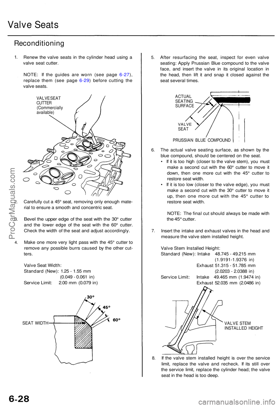
Rene w th e valv e seat s i n th e cylinde r hea d usin g a
valv e sea t cutter .
NOTE : I f th e guide s ar e wor n (se e pag e 6-27 ),
replac e the m (se e pag e 6-29 ) befor e cuttin g th e
valv e seats .
VALV E SEA TCUTTE R(Commerciall yavailable)
Carefully cu t a 45 ° seat , removin g onl y enoug h mate -
ria l t o ensur e a smoot h an d concentri c seat .
Beve l th e uppe r edg e o f th e sea t wit h th e 30 ° cutte r
and th e lowe r edg e o f th e sea t wit h th e 60 ° cutter .
Chec k th e widt h o f th e sea t an d adjus t accordingly .
Mak e on e mor e ver y ligh t pas s wit h th e 45 ° cutte r t o
remov e an y possibl e burr s cause d b y th e othe r cut -
ters .
Valv e Sea t Width :
Standar d (New) : 1.2 5 - 1.5 5 m m
(0.04 9 - 0.06 1 in )
Servic e Limit : 2.0 0 m m (0.07 9 in )
SEA T WIDT H
5.
6.
7 .
8.
Afte r resurfacin g th e seat , inspec t fo r eve n valv e
seating : Appl y Prussia n Blu e compoun d t o th e valv e
face , an d inser t th e valv e i n it s origina l locatio n i n
th e head , the n lif t i t an d sna p i t close d agains t th e
sea t severa l times .
ACTUA L
SEATIN G
SURFAC E
VALVESEAT
PRUSSIA N BLU E COMPOUN D
The actua l valv e seatin g surface , a s show n b y th e
blu e compound , shoul d b e centere d o n th e seat .
• I f i t i s to o hig h (close r t o th e valv e stem) , yo u mus t
mak e a secon d cu t wit h th e 60 ° cutte r t o mov e i t
down , the n on e mor e cu t wit h th e 45 ° cutte r t o
restor e sea t width .
• I f i t i s to o lo w (close r t o th e valv e edge) , yo u mus t
mak e a secon d cu t wit h th e 30 ° cutte r t o mov e i t
up , the n on e mor e cu t wit h th e 45 ° cutte r t o
restor e sea t width .
NOTE : Th e fina l cu t shoul d alway s b e mad e wit h
the 45 ° cutter .
Insert th e intak e an d exhaus t valve s i n th e hea d an d
measur e th e valv e ste m installe d height .
Valv e Ste m Installe d Height :
Standar d (New) : Intak e 48.74 5 - 49.21 5 m m
(1.9191-1.937 6 in )
Exhaus t 51.31 5 - 51.78 5 m m
(2.020 3 - 2.038 8 in )
Servic e Limit : Intak e 49.46 5 m m (1.947 4 in )
Exhaus t 52.03 5 m m (2.048 6 in )
VALV E STE M
INSTALLE D HEIGH T
If th e valv e ste m installe d heigh t i s ove r th e servic e
limit , replac e th e valv e an d recheck . I f it s stil l ove r
th e servic e limit , replac e th e cylinde r head ; th e valv e
sea t i n th e hea d is to o deep .
ProCarManuals.com
Page 1151 of 1771
Valve Bod y Uni t
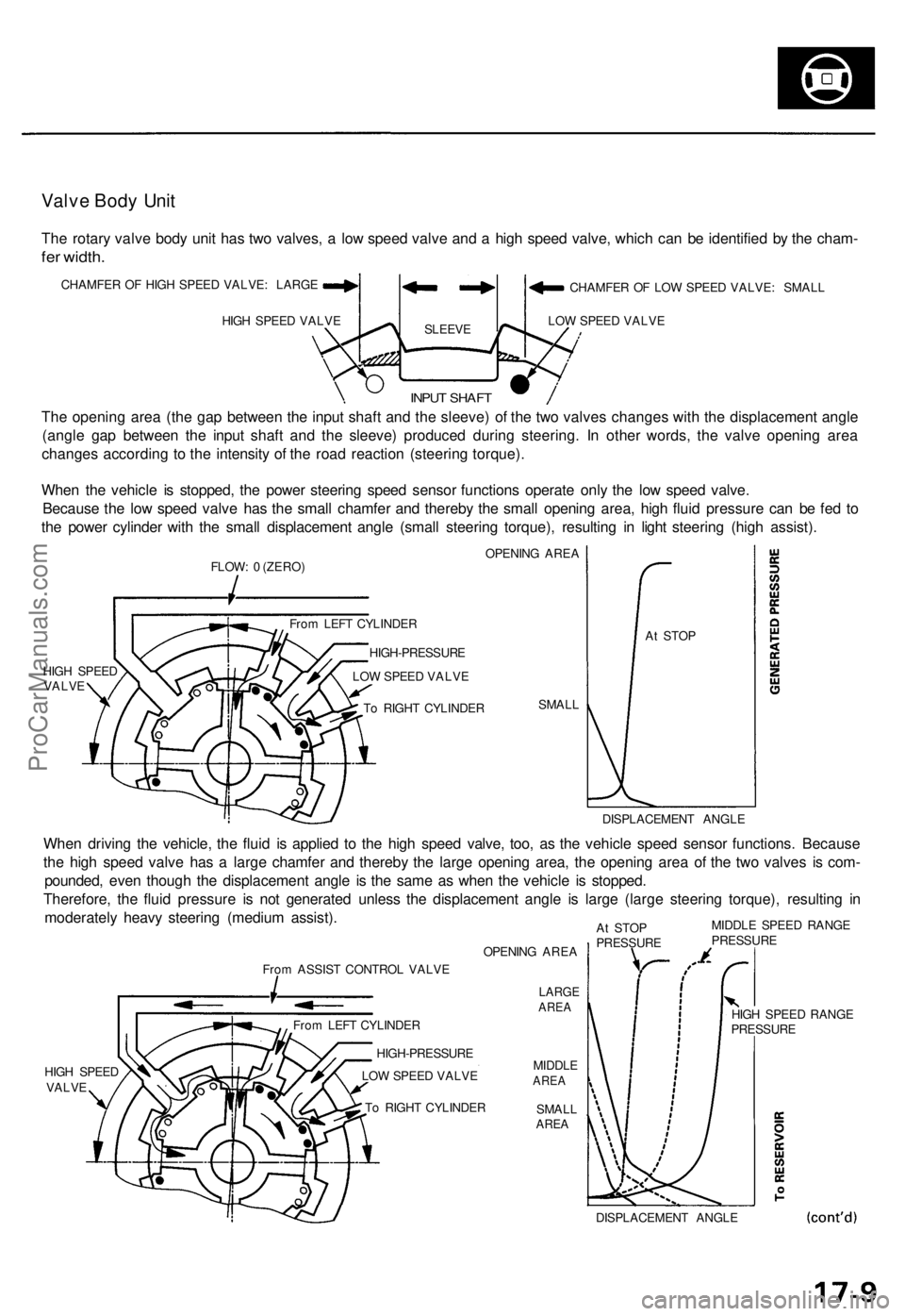
The rotar y valv e bod y uni t ha s tw o valves , a lo w spee d valv e an d a hig h spee d valve , whic h ca n b e identifie d b y th e cham -
fer width.
CHAMFE R O F HIG H SPEE D VALVE : LARG E
HIG H SPEE D VALV E
SLEEV E
CHAMFE R O F LO W SPEE D VALVE : SMAL L
LO W SPEE D VALV E
The openin g are a (th e ga p betwee n th e inpu t shaf t an d th e sleeve ) o f th e tw o valve s change s wit h th e displacemen t angl e
(angl e ga p betwee n th e inpu t shaf t an d th e sleeve ) produce d durin g steering . I n othe r words , th e valv e openin g are a
change s accordin g t o th e intensit y o f th e roa d reactio n (steerin g torque) .
Whe n th e vehicl e i s stopped , th e powe r steerin g spee d senso r function s operat e onl y th e lo w spee d valve .
Becaus e th e lo w spee d valv e ha s th e smal l chamfe r an d thereb y th e smal l openin g area , hig h flui d pressur e ca n b e fe d t o
th e powe r cylinde r wit h th e smal l displacemen t angl e (smal l steerin g torque) , resultin g i n ligh t steerin g (hig h assist) .
FLOW: 0 (ZERO ) OPENIN
G ARE A
HIG H SPEE D
VALV E
SMALL A
t STO P
DISPLACEMEN T ANGL E
When drivin g th e vehicle , th e flui d i s applie d t o th e hig h spee d valve , too , a s th e vehicl e spee d senso r functions . Becaus e
th e hig h spee d valv e ha s a larg e chamfe r an d thereb y th e larg e openin g area , th e openin g are a o f th e tw o valve s i s com -
pounded , eve n thoug h th e displacemen t angl e i s th e sam e a s whe n th e vehicl e i s stopped .
Therefore , th e flui d pressur e i s no t generate d unles s th e displacemen t angl e i s larg e (larg e steerin g torque) , resultin g i n
moderatel y heav y steerin g (mediu m assist) .
From ASSIS T CONTRO L VALV E
HIG H SPEE D
VALV E OPENIN
G ARE A
LARG EAREA
MIDDL EAREA
SMAL LAREA
At STO P
PRESSUR E MIDDL
E SPEE D RANG EPRESSUR E
DISPLACEMEN T ANGL E
T
o RIGH T CYLINDE R
LO
W SPEE D VALV E
HIGH-PRESSUR
E
Fro
m LEF T CYLINDE R HIG
H SPEE D RANG E
PRESSUR E
Fro
m LEF T CYLINDE R
HIGH-PRESSUR E
LO W SPEE D VALV E
T o RIGH T CYLINDE R
INPUT SHAF T
ProCarManuals.com
Page 1387 of 1771
RUBBERDAM
RUBBE RDAM
Mak e a slightl y thicke rbead a t eac h corner .
WINDSHIEL D
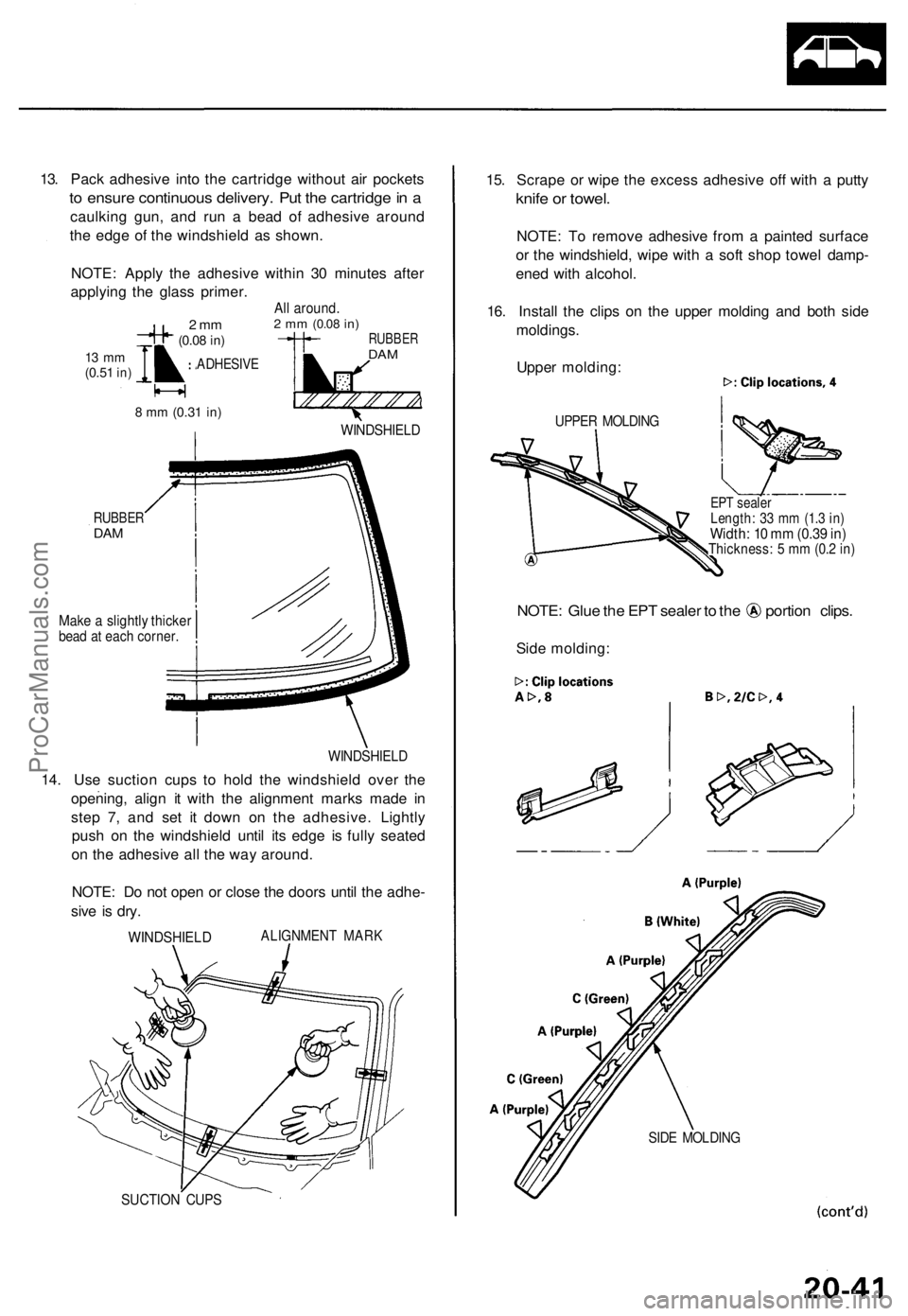
14. Us e suctio n cup s t o hol d th e windshiel d ove r th e
opening , alig n i t wit h th e alignmen t mark s mad e i n
ste p 7 , an d se t i t dow n o n th e adhesive . Lightl y
pus h o n th e windshiel d unti l it s edg e i s full y seated
o n th e adhesiv e al l th e wa y around .
NOTE : D o no t ope n o r clos e th e door s unti l th e adhe -
siv e i s dry .
ALIGNMEN T MAR KWINDSHIEL D
SUCTION CUP S
15. Scrap e o r wip e th e exces s adhesiv e of f wit h a putt y
knife o r towel .
NOTE : T o remov e adhesiv e fro m a painte d surfac e
o r th e windshield , wip e wit h a sof t sho p towe l damp -
ene d wit h alcohol .
16 . Instal l th e clip s o n th e uppe r moldin g an d bot h sid e
moldings .
Uppe r molding :
UPPER MOLDIN G
EPT seale rLength : 3 3 m m (1. 3 in )Width : 1 0 m m (0.3 9 in )Thickness : 5 m m (0. 2 in )
NOTE : Glu e th e EP T seale r t o th e portio n clips .
Side molding :
SIDE MOLDIN G
13. Pac k adhesiv e int o th e cartridg e withou t ai r pocket s
to ensur e continuou s delivery . Pu t th e cartridg e in a
caulkin g gun , an d ru n a bea d o f adhesiv e aroun d
th e edg e o f th e windshiel d a s shown .
NOTE : Appl y th e adhesiv e withi n 3 0 minute s afte r
applyin g th e glas s primer .
ADHESIV E
WINDSHIEL D
22 mm(0.08 in)
13 m m(0.5 1 in)
8 m m (0.3 1 in)
All around .2 m m (0.0 8 in)
ProCarManuals.com
Page 1485 of 1771
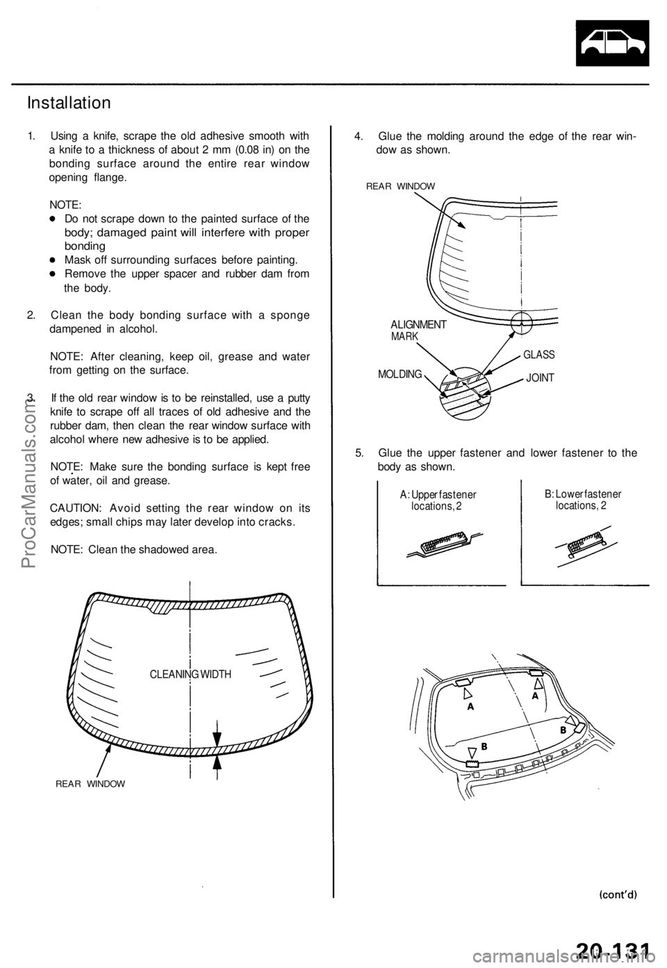
Installation
1. Using a knife, scrape the old adhesive smooth with
a knife to a thickness of about 2 mm (0.08 in) on the
bonding surface around the entire rear window
opening flange.
NOTE:
Do not scrape down to the painted surface of the
body; damaged paint will interfere with proper
bonding
Mask off surrounding surfaces before painting.
Remove the upper spacer and rubber dam from
the body.
2. Clean the body bonding surface with a sponge
dampened in alcohol.
NOTE: After cleaning, keep oil, grease and water
from getting on the surface.
3. If the old rear window is to be reinstalled, use a putty
knife to scrape off all traces of old adhesive and the
rubber dam, then clean the rear window surface with
alcohol where new adhesive is to be applied.
NOTE: Make sure the bonding surface is kept free
of water, oil and grease.
CAUTION: Avoid setting the rear window on its
edges; small chips may later develop into cracks.
NOTE: Clean the shadowed area.
REAR WINDOW
4. Glue the molding around the edge of the rear win-
dow as shown.
REAR WINDOW
ALIGNMENT
MARK
MOLDING
GLASS
JOINT
5. Glue the upper fastener and lower fastener to the
body as shown.
A: Upper fastener
locations, 2
B: Lower fastener
locations, 2
CLEANING WIDTHProCarManuals.com