Page 1251 of 1771
Inspection and Adjustment
Brake Peda l
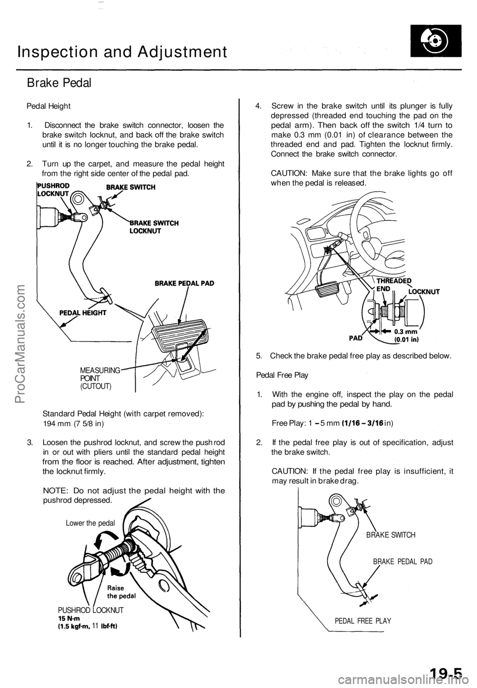
Pedal Heigh t
1 . Disconnec t th e brak e switc h connector , loose n th e
brak e switc h
locknut , and bac k of f th e brak e switc h
unti l i t i s n o longe r touchin g th e brak e pedal .
2 . Tur n u p th e carpet , an d measur e th e peda l heigh t
fro m th e righ t sid e cente r o f th e peda l pad .
MEASURIN GPOINT(CUTOUT )
Standard Peda l Heigh t (wit h carpe t removed) :
194 m m (7 5/ 8 in )
3. Loose n th e pushro d locknut , an d scre w th e pus h rod
i n o r ou t wit h plier s unti l th e standar d peda l heigh t
from th e floo r i s reached . Afte r adjustment , tighte n
the locknu t firmly .
NOTE : D o no t adjus t th e peda l heigh t wit h th e
pushro d depressed .
Lower th e peda l
PUSHRO D LOCKNU T15N-m(1.5kgf-m , 11 Ibf-ft )
4. Scre w in th e brak e switc h unti l it s plunge r i s full y
depresse d (threade d en d touchin g th e pa d o n th e
peda l arm) . The n bac k of f th e switc h 1/ 4 tur n t o
mak e 0. 3 m m (0.0 1 in ) of clearanc e betwee n th e
threade d en d an d pad . Tighte n th e locknu t firmly .
Connec t th e brak e switc h connector .
CAUTION : Mak e sur e tha t th e brak e light s g o of f
whe n th e peda l i s released .
5 . Chec k th e brak e peda l fre e pla y a s describe d below .
Peda l Fre e Pla y
1 . Wit h th e engin e off , inspec t th e pla y o n th e peda l
pad b y pushin g th e peda l b y hand .
Free Play : 1 - 5 m m (1/16-3/1 6 in)
2 . I f th e peda l fre e pla y i s ou t o f specification , adjus t
th e brak e switch .
CAUTION : I f th e peda l fre e pla y i s insufficient , i t
ma y resul t i n brak e drag .
BRAK E SWITC H
BRAKE PEDA L PA D
PEDA L FRE E PLA Y
ProCarManuals.com
Page 1252 of 1771
Inspection an d Adjustmen t
Parking Brak e
Inspectio n
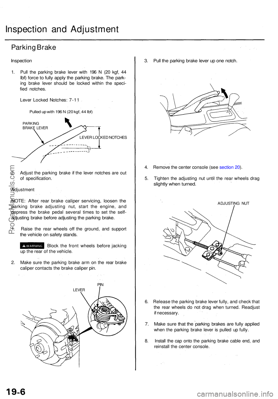
1. Pul l th e parkin g brak e leve r wit h 19 6 N (2 0 kgf , 4 4
Ibf) forc e to full y appl y th e parkin g brake . Th e park -
ing brak e leve r shoul d b e locke d withi n th e speci -
fie d notches .
Leve r Locke d Notches : 7-1 1
Pulle d u p wit h 19 6 N (2 0 kgf , 4 4 Ibf )
PARKIN GBRAKE LEVE R
LEVER LOCKE D NOTCHE S
2.Adjus t th e parkin g brak e i f th e leve r notche s ar e ou t
o f specification .
Adjustmen t
NOTE: Afte r rea r brak e calipe r servicing , loose n th e
parkin g brak e adjustin g nut , star t th e engine , an d
depres s th e brak e peda l severa l time s t o se t th e self -
adjustin g brak e befor e adjustin g th e parkin g brake .
1. Rais e th e rea r wheel s of f th e ground , an d suppor t
the vehicl e o n safet y stands .
Block th e fron t wheel s befor e jackin g
u p th e rea r o f th e vehicle .
2 . Mak e sur e th e parkin g brak e ar m o n th e rea r brak e
calipe r contact s th e brak e calipe r pin .
PIN
LEVE R
3. Pul l th e parkin g brak e leve r u p on e notch .
4. Remov e th e cente r consol e (se e sectio n 20 ).
5 . Tighte n th e adjustin g nu t unti l th e rea r wheel s dra g
slightl y whe n turned .
ADJUSTIN G NU T
6. Releas e th e parkin g brak e leve r fully , an d chec k tha t
th e rea r wheel s d o no t dra g whe n turned . Readjus t
i f necessary .
7. Mak e sur e tha t th e parkin g brake s ar e full y applie d
when th e parkin g brak e leve r i s pulle d u p fully .
8 . Instal l th e ca p ont o th e parkin g brak e cabl e end , an d
reinstal l th e cente r console .
ProCarManuals.com
Page 1254 of 1771
Front Brak e Pad s
Inspectio n an d Replacemen t
• Neve r us e a n ai r hos e o r dr y brus h t o clea n brak e
assemblies .
• Us e a n OSHA-approve d vacuu m cleane r t o avoi d
breathin g brak e dust .
1 . Loose n th e fron t whee l nut s slightly , the n rais e th e
vehicle , an d suppor t i t o n safet y stands . Remov e
the fron t wheels .
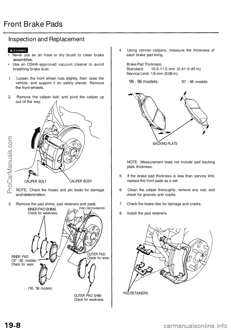
2. Remov e th e calipe r bolt , an d pivo t th e calipe r u p
ou t o f th e way .
CALIPE R BOL T CALIPE
R BOD Y
NOTE : Chec k th e hose s an d pi n boot s fo r damag e
and deterioration .
3. Remov e th e pa d shims , pa d retainer s an d pads .
INNER PA D SHIM SCheck fo r weakness .
INNE R PA D
('9 7 -9 8 models )
Chec k fo r wear . OUTE
R PA D
Chec k fo r wear .
('95 , '9 6 models )
OUTER PA D SHI M
Chec k fo r weakness .
4. Usin g vernie r calipers , measur e th e thicknes s o f
eac h brak e pa d lining .
Brak e Pa d Thickness :
Standard: 10.5-11. 5 m m (0.41-0.4 5 in )
Servic e Limit : 1. 6 m m (0.0 6 in )
'95 - 9 6 models : '9 7 - 9 8 models :
BACKIN G PLAT E
NOTE : Measuremen t doe s no t includ e pa d backin g
plat e thickness .
5 . I f th e brak e pa d thicknes s i s les s tha n servic e limit ,
replac e th e fron t pad s a s a set .
6 . Clea n th e calipe r thoroughly ; remov e an y rust , an d
chec k fo r groove s an d cracks .
7 . Chec k th e brak e dis c fo r damag e an d cracks .
8 . Instal l th e pa d retainers .
PAD RETAINER S
PAD RETAINER S
ProCarManuals.com
Page 1256 of 1771
Front Brak e Dis c
Disc Runou t Inspectio n
1. Loose n th e fron t whee l nut s slightly , the n rais e th e
vehicle , an d suppor t i t o n safet y stands . Remov e
th e fron t wheels .
2 . Remov e th e brak e pad s (se e pag e 19-8 ).
3 . Inspec t th e dis c surfac e fo r damag e an d cracks .
Clea n th e dis c thoroughl y an d remov e al l rust .
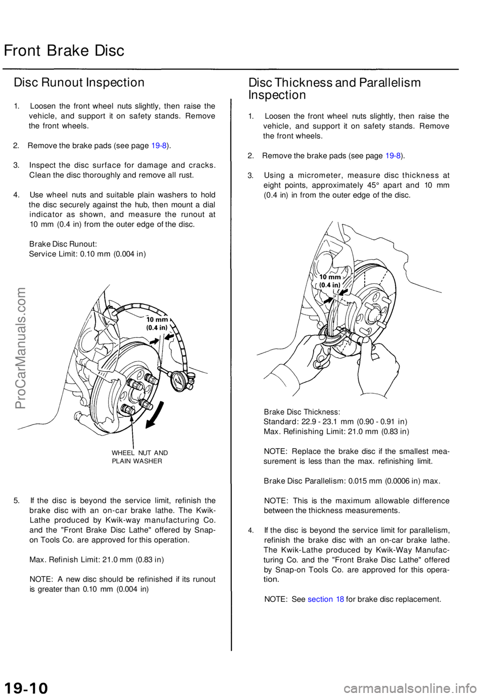
4 . Us e whee l nut s an d suitabl e plai n washer s t o hol d
th e dis c securel y agains t th e hub , the n moun t a dia l
indicato r a s shown , an d measur e th e runou t a t
1 0 m m (0. 4 in ) fro m th e oute r edg e o f th e disc .
Brak e Dis c Runout :
Servic e Limit : 0.1 0 m m (0.00 4 in )
WHEE L NU T AN D
PLAI N WASHE R
5. I f th e dis c i s beyon d th e servic e limit, refinis h th e
brak e dis c wit h a n on-ca r brak e lathe . Th e Kwik -
Lath e produce d b y Kwik-wa y manufacturin g Co .
an d th e "Fron t Brak e Dis c Lathe " offere d b y Snap -
o n Tool s Co . ar e approve d fo r thi s operation .
Max . Refinis h Limit : 21. 0 m m (0.8 3 in )
NOTE : A ne w dis c shoul d b e refinishe d i f it s runou t
i s greate r tha n 0.1 0 m m (0.00 4 in )
Dis c Thicknes s an d Parallelis m
Inspection
1. Loose n th e fron t whee l nut s slightly , the n rais e th e
vehicle , an d suppor t i t o n safet y stands . Remov e
th e fron t wheels .
2 . Remov e th e brak e pad s (se e pag e 19-8 ).
3 .
4 .
Usin g a micrometer , measur e dis c thicknes s a t
eigh t points , approximatel y 45 ° apar t an d 1 0 m m
(0. 4 in ) i n fro m th e oute r edg e o f th e disc .
Brak e Dis c Thickness :
Standard: 22. 9 - 23. 1 m m (0.9 0 - 0.9 1 in )
Max . Refinishin g Limit : 21. 0 m m (0.8 3 in )
NOTE : Replac e th e brak e dis c i f th e smalles t mea -
suremen t i s les s tha n th e max . refinishin g limit .
Brak e Dis c Parallelism : 0.01 5 m m (0.000 6 in ) max .
NOTE : Thi s i s th e maximu m allowabl e differenc e
betwee n th e thicknes s measurements .
I f th e dis c i s beyon d th e servic e limi t fo r parallelism ,
refinis h th e brak e dis c wit h a n on-ca r brak e lathe .
Th e Kwik-Lath e produce d b y Kwik-Wa y Manufac -
turin g Co . an d th e "Fron t Brak e Dis c Lathe " offere d
b y Snap-o n Tool s Co . ar e approve d fo r thi s opera -
tion.
NOTE : Se e sectio n 1 8 fo r brak e dis c replacement .
ProCarManuals.com
Page 1263 of 1771
Brake Booster
Inspection
Functional Test
1. With the engine stopped, depress the brake pedal
several times to deplete the vacuum reservoir, then
depress the pedal hard and hold it for 15 seconds. If
the pedal sinks, either the master cylinder is
bypassing internally, or the brake system (master
cylinder, lines, modulator, proportioning valve, or
caliper) is leaking.
2. Start the engine with the pedal depressed. If the
pedal sinks slightly, the vacuum booster is operat-
ing normally. If the pedal height does not vary, the
booster or check valve is faulty.
3. With the engine running, depress the brake pedal
lightly. Apply just enough pressure to hold back
automatic transmission creep. If the brake pedal
sinks more than 25 mm (1.0 in.) in three minutes, the
master cylinder is faulty. A slight change in pedal
height when the A/C compressor cycles on and off if
normal. (The A/C compressor load changes the vac-
uum available to the booster.)
Leak Test
1. Depress the brake pedal with the engine running,
then stop the engine. If the pedal height does not
vary while depressed for 30 seconds, the vacuum
booster is OK. If the pedal rises, the booster is faulty.
2. With the engine stopped, depress the brake pedal
several times using normal pressure. When the
pedal is first depressed, it should be low. On consec-
utive applications, the pedal height should gradually
rise. If the pedal position does not vary, check the
booster check valve.ProCarManuals.com
Page 1267 of 1771
Rear Brake Pads
Inspection and Replacement
• Never use an air hose or dry brush to clean brake
assemblies.
• Use an OSHA-approved vacuum cleaner to avoid
breathing brake dust.
1. Block the front wheels, loosen the rear wheel nuts
slightly, support the rear of vehicle on safety
stands, then remove the rear wheels.
2. Release the parking brake.
3. Remove the two caliper bolts and the caliper from
the bracket.
CAUTION:
• Thoroughly clean the outside of the caliper to pre-
vent dust and dirt from entering inside.
• Support the caliper with a piece of wire so that
it does not hang from the brake hose.
CALIPER BOLTS
CALIPER
4. Remove the pad shims and brake pads.
OUTER PAD
SHIM
Check for weakness.
INNER PAD
SHIM
Check for weakness.
REAR BRAKE PADS
Check for wear.ProCarManuals.com
Page 1270 of 1771
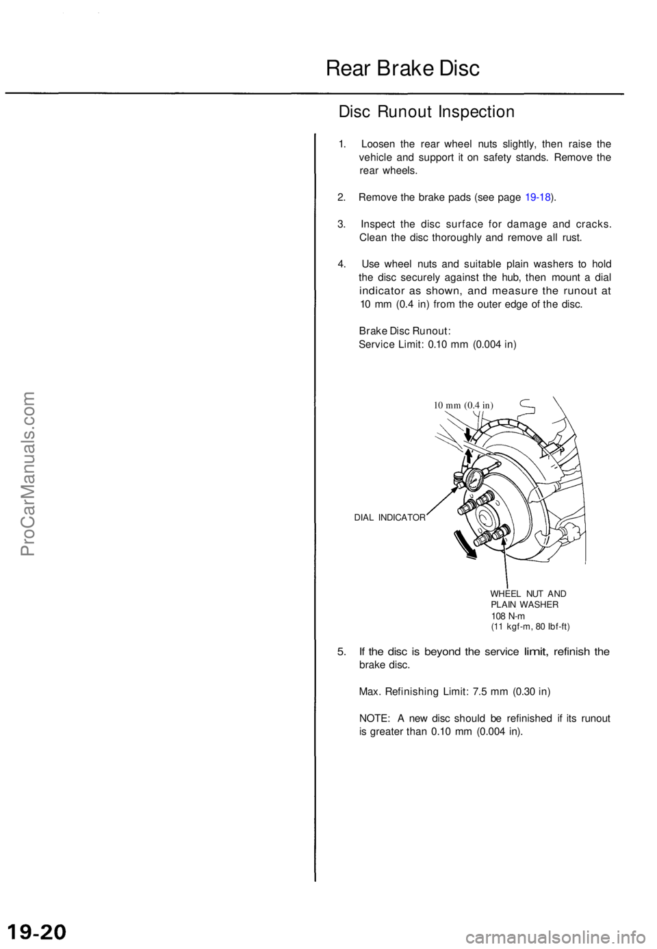
Rear Brak e Dis c
Disc Runou t Inspectio n
1. Loose n th e rea r whee l nut s slightly , the n rais e th e
vehicl e an d suppor t i t o n safet y stands . Remov e th e
rea r wheels .
2 . Remov e th e brak e pad s (se e pag e 19-18 ).
3 . Inspec t th e dis c surfac e fo r damag e an d cracks .
Clea n th e dis c thoroughl y an d remov e al l rust .
4 . Us e whee l nut s an d suitabl e plai n washer s t o hol d
th e dis c securel y agains t th e hub , the n moun t a dia l
indicato r a s shown , an d measur e th e runou t a t
10 m m (0. 4 in ) fro m th e oute r edg e o f th e disc .
Brak e Dis c Runout :
Servic e Limit : 0.1 0 m m (0.00 4 in )
10 m m (0. 4 in)
DIA L INDICATO R
WHEEL NU T AN D
PLAI N WASHE R
108 N- m(11 kgf-m , 8 0 Ibf-ft )
5. I f th e dis c is beyon d the servic e limit, refinis h the
brak e disc .
Max . Refinishin g Limit : 7. 5 m m (0.3 0 in )
NOTE : A ne w dis c shoul d b e refinishe d i f it s runou t
i s greate r tha n 0.1 0 m m (0.00 4 in) .
ProCarManuals.com
Page 1271 of 1771
Disc Thicknes s an d Parallelis m
Inspectio n
1. Loose n th e rea r whee l nut s slightly , the n rais e th e
vehicl e an d suppor t i t o n safet y stands . Remov e th e
rea r wheels .
2 . Remov e th e brak e pad s (se e pag e 19-18 ).
3 . Usin g a micrometer , measur e dis c thicknes s a t
eigh t points , approximatel y 45 ° apar t an d 1 0 m m
(0.4 in ) i n fro m th e oute r edg e o f th e disc .
MICROMETE R
Brake Dis c Thickness :
Standard: 8. 9 - 9. 1 m m (0.35 0 - 0.35 8 in )
Max . Refinishin g Limit : 7. 5 m m (0.3 0 in )
NOTE : Replac e th e brak e dis c i f th e smalles t mea -
suremen t i s les s tha n th e max . refinishin g limit .
Brak e Dis c Parallelism : 0.01 5 m m
(0.000 6 in ) max .
NOTE : Thi s i s th e maximu m allowabl e differenc e
between th e thicknes s measurements .
4. I f th e dis c i s beyon d th e servic e limi t fo r parallelism,
refinis h th e brak e disc .
NOTE : Se e pag e 18-2 7 fo r brak e dis c replacement .
ProCarManuals.com