1995 ACURA TL light
[x] Cancel search: lightPage 819 of 1771
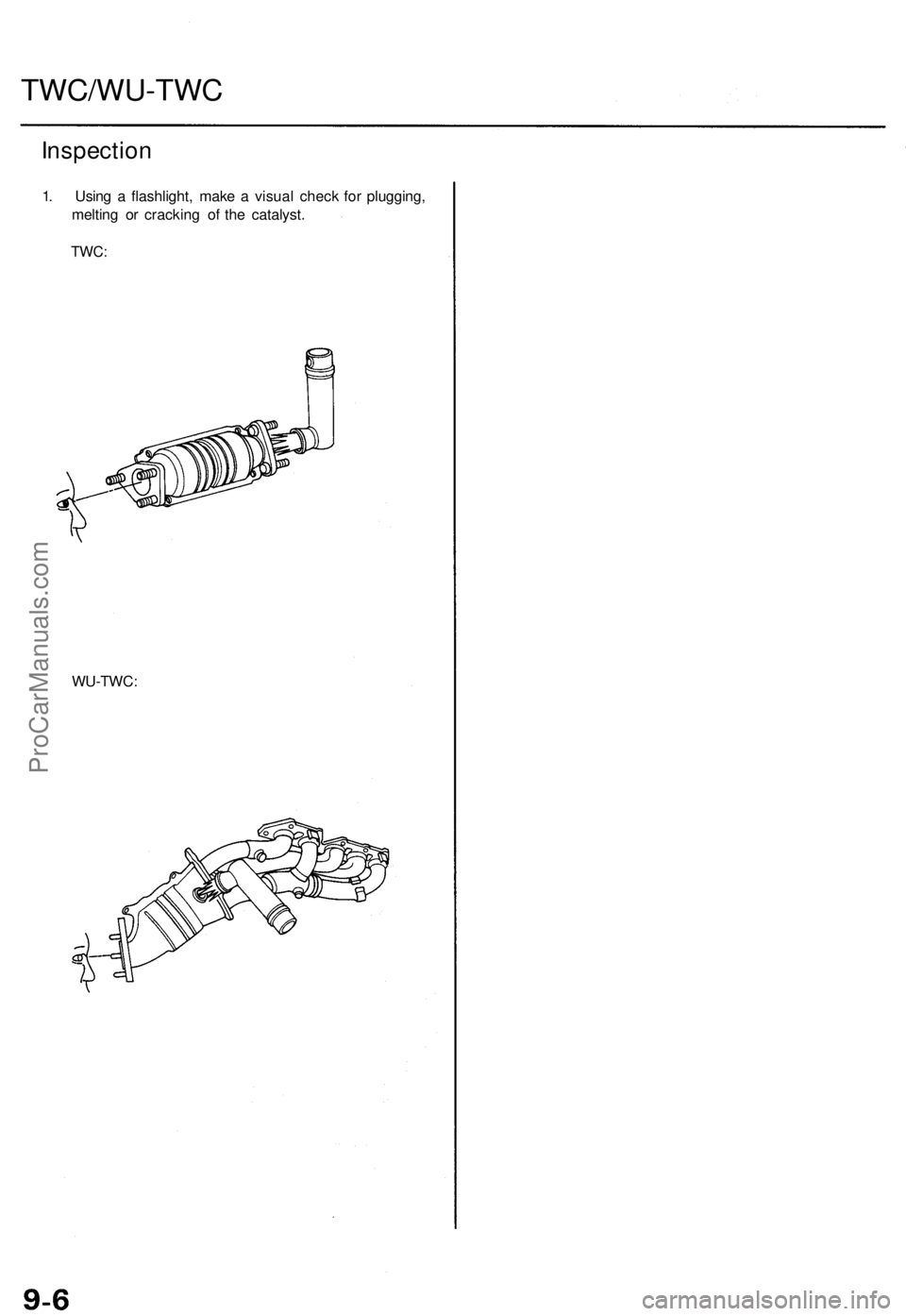
TWC/WU-TWC
Inspection
1. Usin g a flashlight , mak e a visua l chec k fo r plugging ,
meltin g o r crackin g o f th e catalyst .
TWC:
WU-TWC :
ProCarManuals.com
Page 864 of 1771
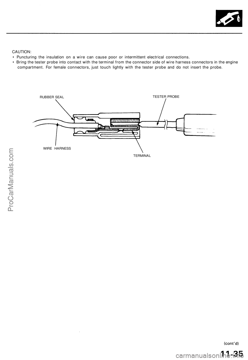
CAUTION:
• Puncturing the insulation on a wire can cause poor or intermittent electrical connections.
• Bring the tester probe into contact with the terminal from the connector side of wire harness connectors in the engine
compartment. For female connectors, just touch lightly with the tester probe and do not insert the probe.
RUBBER SEAL
TESTER PROBE
WIRE HARNESS
TERMINALProCarManuals.com
Page 878 of 1771
4. A/ C Compresso r Clutc h Rela y
When th e EC M receive s a deman d fo r coolin g fro m th e ai r conditionin g system , i t delay s th e compresso r fro m bein g
energized , an d enriche s th e mixtur e to assur e smoot h transitio n to th e A/ C mode .
5 . Evaporativ e Emissio n (EVAP ) Purg e Contro l Solenoi d Valv e
Whe n th e engin e coolan t temperatur e i s belo w 167° F (75°C ) ('9 7 - 9 8 models : 158° F (70°C) , th e EC M control s th e
EVA P purg e contro l solenoi d valv e whic h cut s vacuu m to th e EVA P purg e contro l caniste r diaphragm .
6 . Intak e Ai r Bypas s (IAB ) Contro l Solenoi d Valv e
Whe n th e engin e spee d i s belo w 4,80 0 rpm , th e IA B contro l solenoi d valv e i s activate d b y a signa l fro m th e ECM ,
intak e ai r flow s throug h th e smalle r chamber , the n hig h torqu e i s delivered. At speed s highe r tha n 4,80 0 rpm , th e
solenoi d valv e i s deactivate d b y th e ECM , an d intak e ai r flow s throug h th e large r chambe r i n orde r t o reduc e th e
resistanc e in airflow .
7 . Exhaus t Ga s Recirculatio n (EGR ) Contro l Solenoi d Valv e
Whe n th e EG R is require d fo r contro l o f oxide s o f nitroge n (NOx ) emissions , th e EC M control s th e EG R contro l
solenoi d valv e whic h supplie s regulate d vacuu m to th e EG R valve .
8 . Alternato r Contro l
Th e syste m control s th e voltag e generate d a t th e alternato r i n accordanc e wit h th e electrica l loa d an d drivin g mode ,
whic h reduce s th e engin e loa d to improv e th e fue l economy .
ECM Fail-safe/Back-u p Function s
1. Fail-saf e Functio n
Whe n a n abnormalit y occur s in a signa l fro m a sensor , th e EC M ignore s tha t signa l an d assume s a pre-programme d
valu e fo r tha t senso r tha t allow s th e engin e to continu e to run .
2 . Back-u p Functio n
Whe n a n abnormalit y occur s in th e EC M itself , th e fue l injector s ar e controlle d b y a back-u p circui t independen t o f th e
syste m in orde r t o permi t minima l driving .
3 . Self-diagnosi s Functio n [Malfunctio n Indicato r Lam p (MIL) ]
Whe n a n abnormalit y occur s i n a signa l fro m a sensor , th e EC M supplie s groun d fo r th e MI L an d store s th e DT C in
erasable memory . Whe n th e ignitio n i s initiall y turne d on , th e EC M supplie s ground for th e MI L fo r tw o second s t o
chec k th e MI L bul b condition .
4 . Tw o Tri p Detectio n Metho d ('9 5 - 9 6 models )
T o preven t fals e indications , th e Tw o Tri p Detectio n Metho d is use d fo r th e MA F sensor , H02S , fue l metering-related ,
idl e contro l system , EC T sensor , an d EG R syste m self-diagnosti c functions . Whe n a n abnormalit y occurs , th e EC M
store s i t i n it s memory . Whe n th e sam e abnormalit y recur s afte r th e ignitio n switc h i s turne d OF F an d O N (II ) again ,
th e EC M inform s th e drive r b y lightin g th e MIL .
However ,
to eas e troubleshooting , thi s functio n is cancelle d when you shor t the servic e check connector . The MI L will
the n blin k immediatel y whe n a n abnormalit y occurs .
5 . Tw o (o r Three ) Drivin g Cycl e Detectio n Metho d ('9 5 - 9 6 models )
A "Drivin g Cycle " consist s o f startin g th e engine , beginnin g close d loo p operation , an d stoppin g th e engine . I f misfir -
in g tha t increase s emission s o r EVA P contro l syste m malfunctio n i s detecte d i n tw o consecutiv e drivin g cycles , o r
TW C deterioratio n is detecte d in thre e consecutiv e drivin g cycles , th e EC M turn s th e MI L on .
However , t o eas e troubleshooting , thi s functio n is cancelle d whe n yo u shor t th e servic e chec k connector . Th e MI L wil l
the n blin k immediatel y whe n a n abnormalit y occurs .
6 . Tw o Drivin g Cycl e Detectio n Metho d ('9 7 - 9 8 models )
T o preven t fals e indications , th e "tw o drivin g cycl e detectio n method " i s use d fo r th e H02S , fue l metering-related ,
idl e contro l system , EC T sensor , EG R system , TW C an d EVA P contro l syste m an d othe r self-diagnosti c functions .
Whe n a n abnormalit y occurs , th e EC M store s i t i n it s memory . Whe n th e sam e abnormalit y recur s afte r switc h i s
turne d OF F an d O N (II ) again , th e EC M inform s th e drive r b y turnin g o n th e MIL .
ProCarManuals.com
Page 879 of 1771
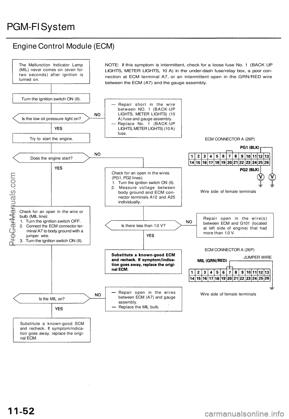
PGM-FI System
Engine Control Module (ECM)
Is the low oil pressure light on?
Try to start the engine.
Does the engine start?
Check for an open in the wire or
bulb (MIL line):
1. Turn the ignition switch OFF.
2. Connect the ECM connector ter-
minal A7 to body ground with a
jumper wire.
3. Turn the ignition switch ON (II).
NOTE: If this symptom is intermittent, check for a loose fuse No. 1 (BACK UP
LIGHTS, METER LIGHTS, 10 A) in the under-dash fuse/relay box, a poor con-
nection at ECM terminal A7, or an intermittent open in the GRN/RED wire
between the ECM (A7) and the gauge assembly.
Is the MIL on?
Substitute a known-good ECM
and recheck. If symptom/indica-
tion goes away, replace the origi-
nal
ECM.
— Repair short in the wire
between NO. 1 (BACK-UP
LIGHTS, METER LIGHTS) (10
A) fuse and gauge assembly.
— Replace No. 1 (BACK-UP
LIGHTS, METER LIGHTS) (10 A)
fuse.
Check for an open in the wires
(PG1, PG2 lines):
1. Turn the ignition switch ON (II).
2. Measure voltage between
body ground and ECM con-
nector terminals A12 and A25
individually.
Is there less than 1.0 V?
Repair open in the wires
between ECM (A7) and gauge
assembly.
Replace the MIL bulb.
ECM CONNECTOR A (26P)
Wire side of female terminals
Repair open in the wire(s)
between ECM and G101 (located
at left side of engine) that had
more than 1.0 V.
ECM CONNECTOR A (26P)
Wire side of female terminals
The Malfunction Indicator Lamp
(MIL) never comes on (even for
two seconds) after ignition is
turned on.
Turn the ignition switch ON (II).
JUMPER WIREProCarManuals.com
Page 888 of 1771
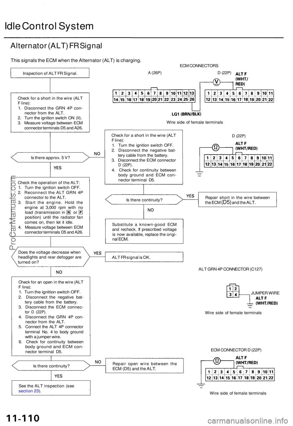
Idle Contro l Syste m
Alternato r (ALT ) F R Signa l
This signal s th e EC M whe n th e Alternato r (ALT ) i s charging .
Is ther e approx . 5 V ?
Chec k th e operatio n o f th e ALT :
1 . Tur n th e ignitio n switc h OFF .
2 . Reconnec t th e AL T GR N 4 P
connecto r t o th e ALT .
3 . Star t th e engine . Hol d th e
engin e a t 3,00 0 rp m wit h n o
loa d (transmissio n in o r
position ) unti l th e radiato r fa n
come s on , the n le t i t idle .
4 . Measur e voltag e betwee n EC M
connecto r terminal s D 5 an d A26 .
Doe s th e voltag e decreas e whe n
headlight s an d rea r defogge r ar e
turne d on ?
Chec k fo r a n ope n in th e wir e (AL T
F line) :
1. Tur n th e ignitio n switc h OFF .2. Disconnec t th e negativ e bat -
ter y cabl e fro m th e battery .
3 . Disconnec t th e EC M connec -
tor D (22P) .4. Disconnec t th e GR N 4 P con -
necto r fro m th e ALT .
5 . Connec t th e AL T 4 P connecto r
termina l No . 4 to bod y groun d
with a jumpe r wire .6. Chec k fo r continuit y betwee nbody groun d an d EC M con -necto r termina l D5 .
I s ther e continuity ?
Se e th e AL T inspectio n (se e
sectio n 23 ). EC
M CONNECTOR S
A (26P)D (22P)
Wire sid e o f femal e terminal s
D (22P)
Repai r shor t i n th e wir e betwee nthe EC M (D5 ) and th e ALT .
ALT F R signa l i s OK .
ALT GR N 4P CONNECTO R (C127 )
JUMPE R WIR E
Wir e sid e o f femal e terminal s
Repai r ope n wir e betwee n th e
ECM (D5 ) and th e ALT .
ECM CONNECTO R D (22P )
Wir e sid e o f femal e terminal s
Substitut
e a known-goo d EC M
an d recheck . I f prescribe d voltag e
i s no w available , replac e th e origi -
nal ECM .
Is ther e continuity ?
Chec
k fo r a shor t i n th e wir e (AL T
F line) :
1 . Tur n th e ignitio n switc h OFF .
2 . Disconnec t th e negativ e bat -
ter y cabl e fro m th e battery .
3 . Disconnec t th e EC M connecto r
D (22P) .4. Chec k fo r continuit y betwee n
bod y groun d an d EC M con -
necto r termina l D5 .
Chec
k fo r a shor t i n th e wir e (AL T
F line) :
1 . Disconnec t th e GR N 4 P con -
necto r fro m th e ALT .
2 . Tur n th e ignitio n switc h O N (II) .
3 . Measur e voltag e betwee n EC M
connecto r terminal s D 5 an d A26 .
Inspectio
n o f AL T F R Signal .
ProCarManuals.com
Page 889 of 1771
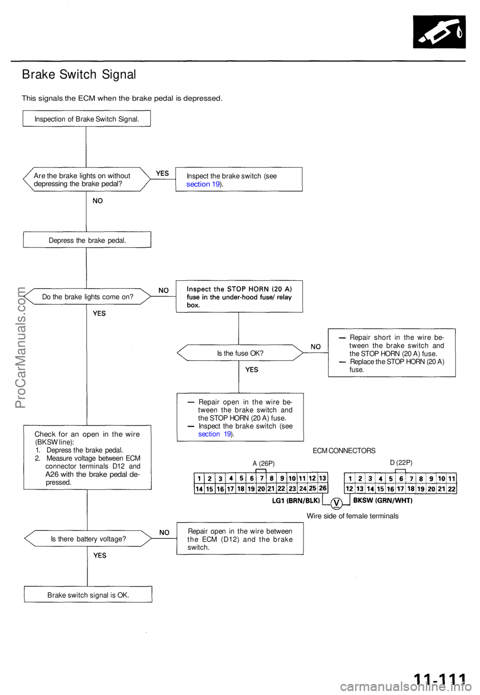
Brake Switc h Signa l
This signal s th e EC M whe n th e brak e peda l i s depressed .
Inspection o f Brak e Switc h Signal .
Are th e brak e light s o n withou tdepressin g th e brak e pedal ?Inspec t th e brak e switc h (se e sectio n 19 ).
Depres s th e brak e pedal .
D o th e brak e light s com e on ?
Is th e fus e OK ?
Chec k fo r a n ope n i n th e wir e(BKS W line) :
1 . Depres s th e brak e pedal .
2 . Measur e voltag e betwee n EC M
connecto r terminal s D1 2 an d
A26 wit h th e brak e peda l de -pressed . Repai
r shor t i n th e wir e be -
twee n th e brak e switc h an d
th e STO P HOR N (2 0 A ) fuse .
Replac e th e STO P HOR N (2 0 A )
fuse .
ECM CONNECTOR S
A (26P)D (22P )
Wire sid e o f femal e terminal s
Is ther e batter y voltage ? Repai
r ope n i n th e wir e betwee n
th e EC M (D12 ) an d th e brak e
switch .
Brak e switc h signa l i s OK . Repai
r ope n i n th e wire be-
twee n th e brak e switc h an d
th e STO P HOR N (2 0 A ) fuse .
Inspec t th e brak e switc h (se e
sectio n 19 ).
ProCarManuals.com
Page 895 of 1771
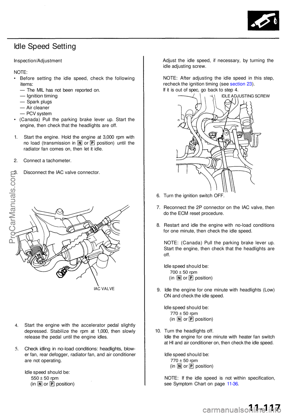
Idle Spee d Settin g
Inspection/Adjustmen t
NOTE:
• Befor e settin g th e idl e speed , chec k th e followin g
items:
— Th e MI L ha s no t bee n reporte d on .
— Ignitio n timin g
— Spar k plug s
— Ai r cleane r
— PC V syste m
• (Canada ) Pul l th e parkin g brak e leve r up . Star t th e
engine , the n chec k tha t th e headlight s ar e off .
1 . Star t th e engine . Hol d th e engine at 3,00 0 rp m wit h
no loa d (transmissio n i n o r position ) unti l th e
radiato r fa n come s on , the n le t i t idle .
2 . Connec t a tachometer .
3 . Disconnec t th e IA C valv e connector .
IAC VALV E
4.
5.
Star t th e engin e wit h th e accelerato r peda l slightl y
depressed . Stabiliz e th e rp m a t 1,000 , the n slowl y
releas e th e peda l unti l th e engin e idles .
Check idlin g in no-loa d conditions : headlights , blow -
er fan , rea r defogger , radiato r fan , an d ai r conditione r
ar e no t operating .
Idl e spee d shoul d be :
550 ± 5 0 rp m
(in o r position )
Adjust th e idl e speed , i f necessary, by turnin g th e
idl e adjustin g screw .
NOTE : Afte r adjustin g th e idl e spee d i n thi s step ,
rechec k th e ignitio n timin g (se e sectio n 23 ).
I f i t i s ou t o f spec , g o bac k t o ste p 4 .
IDL E ADJUSTIN G SCRE W
6. Tur n th e ignitio n switc h OFF .
7 . Reconnec t th e 2 P connecto r o n th e IA C valve , the n
d o th e EC M rese t procedure .
8 . Restar t an d idl e th e engine with no-loa d condition s
fo r on e minute , the n chec k th e idl e speed .
NOTE : (Canada ) Pul l th e parkin g brak e leve r up .
Star t th e engine , the n chec k tha t th e headlight s ar e
off.
Idle spee d shoul d be :
700 ± 5 0 rp m
(in o r position )
9 . Idl e th e engin e fo r on e minut e wit h headlight s (Low )
O N an d chec k th e idl e speed .
Idl e spee d shoul d be :
770 ± 5 0 rp m
(in o r position )
10 . Tur n th e headlight s off .
Idl e th e engin e fo r on e minut e wit h heate r fa n switc h
a t H I an d ai r conditione r on , the n chec k th e idl e speed .
Idl e spee d shoul d be :
770 ± 5 0 rp m
(in o r position )
NOTE : I f th e idl e spee d i s no t withi n specification ,
se e Sympto m Char t o n pag e 11-36 .
ProCarManuals.com
Page 920 of 1771
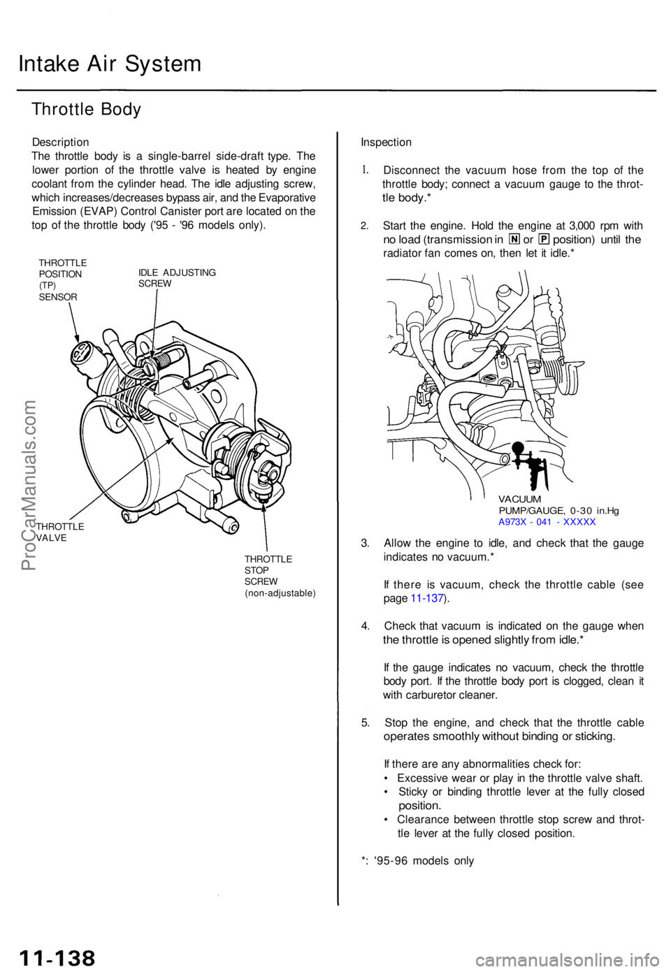
Intake Ai r Syste m
Throttl e Bod y
Descriptio n
The throttl e bod y i s a single-barre l side-draf t type . Th e
lowe r portio n o f th e throttl e valv e i s heate d b y engin e
coolan t fro m th e cylinde r head . Th e idl e adjustin g screw ,
whic h increases/decrease s bypas s air , an d th e Evaporativ e
Emissio n (EVAP ) Contro l Caniste r por t ar e locate d o n th e
to p o f th e throttl e bod y ('9 5 - '9 6 model s only) .
THROTTL E
POSITIO N
(TP)SENSO R IDL
E ADJUSTIN G
SCREW
THROTTL EVALVE
THROTTL ESTOPSCRE W(non-adjustable )
Inspection
1.
2 .
Disconnec t th e vacuu m hos e fro m th e to p of the
throttl e body ; connec t a vacuu m gaug e t o th e throt -
tle body. *
Start th e engine . Hol d th e engin e a t 3,00 0 rp m wit h
no loa d (transmissio n in o r position ) unti l th e
radiato r fa n come s on , the n le t i t idle. *
VACUU MPUMP/GAUGE , 0-3 0 in.H gA973 X - 04 1 - XXXX X
3. Allo w th e engin e t o idle , an d chec k tha t th e gaug e
indicate s n o vacuum. *
I f ther e i s vacuum , chec k th e throttl e cabl e (se e
pag e 11-137 ).
4 . Chec k tha t vacuu m is indicate d o n th e gaug e whe n
the throttl e is opene d slightl y fro m idle. *
If th e gaug e indicate s n o vacuum , chec k th e throttl e
bod y port . I f th e throttl e bod y por t i s clogged , clea n i t
wit h carbureto r cleaner .
5 . Sto p th e engine , an d chec k tha t th e throttl e cabl e
operates smoothly withou t bindin g o r sticking .
If ther e ar e an y abnormalitie s chec k for :
• Excessiv e wea r o r pla y i n th e throttl e valv e shaft .
• Stick y o r bindin g throttl e leve r a t th e full y close d
position .
• Clearanc e betwee n throttl e sto p scre w an d throt -
tl e leve r a t th e full y close d position .
* : '95-9 6 model s onl y
ProCarManuals.com