1995 ACURA TL light
[x] Cancel search: lightPage 1681 of 1771
Switch Tes t
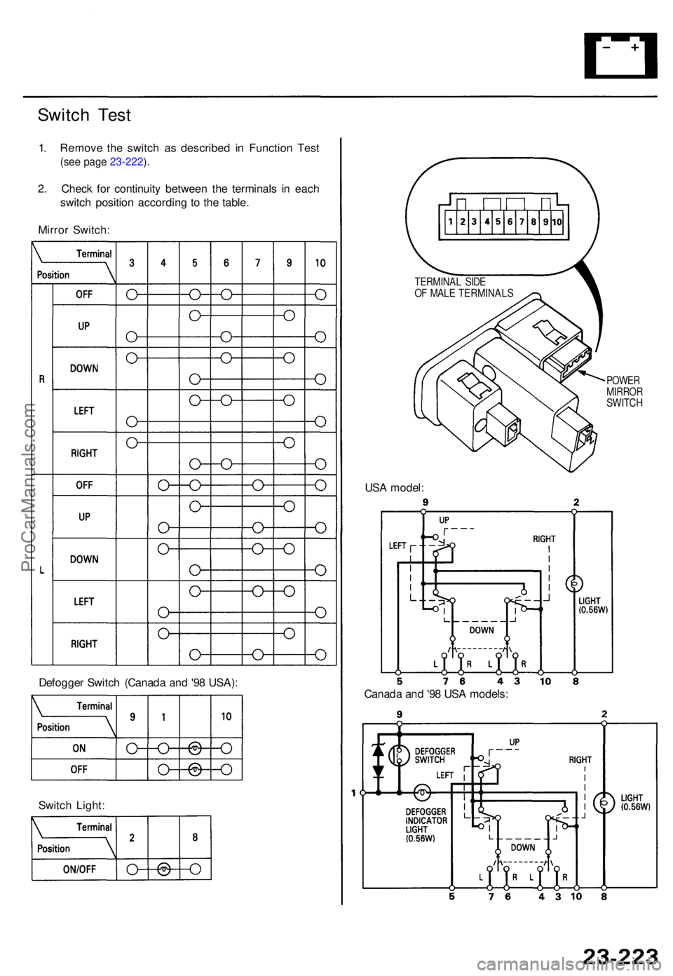
1. Remov e th e switc h a s describe d i n Functio n Tes t
(see pag e 23-222 ).
2 . Chec k fo r continuit y betwee n th e terminal s i n eac h
switc h positio n accordin g t o th e table .
Mirro r Switch :
Defogge r Switc h (Canad a an d '9 8 USA) :
Switc h Light : US
A model :
POWERMIRRO RSWITCH
Canada an d '9 8 US A models :
TERMINA L SID E
O F MAL E TERMINAL S
ProCarManuals.com
Page 1716 of 1771
Description
The cruise control system uses mechanically and electri-
cally operated devices to maintain vehicle speed at a
setting selected by the driver.
The cruise control unit receives command signals from
the cruise control main switch and the cruise control
set/resume/cancel switch. It receives information about
operating conditions from the brake switch, ECM, vehi-
cle speed sensor (VSS), or the A/T gear position switch.
The cruise control unit sends operational signals to the
devices that regulate the throttle position. The throttle
position maintains the selected vehicle speed.
Essentially, the control unit compares the actual speed
of the vehicle to the selected speed. Then, the control
unit uses the result of that comparison to open or close
the throttle.
The brake switch releases the system's control of the
throttle at the instant the driver depresses the brake
pedal. The switch sends an electronic signal to the con-
trol unit when the brake pedal is depressed; the control
unit responds by allowing the throttle to close. The A/T
gear position switch sends a disengage signal input to
the control unit that also allows the throttle to close.
Operation:
The cruise control system will set and automatically
maintain any speed above 25 mph (40 km/h). To set a
speed, make sure that the main switch is in the "ON"
position. After reaching the desired speed, press the set
switch. The cruise control unit will receive a set signal
and, in turn, will actuate the cruise control actuator. If
you depress the set switch is when the cruise control
system is on, the "cruise light", an indicator in the
gauge assembly, will come on. You can cancel the
cruise control system by depressing the cancel switch or
by pushing the main switch to "OFF". This removes
power to the control unit and erases the set speed from
memory. If the system is disengaged temporarily by the
brake switch or the A/T gear position switch and vehicle
speed is still above 25 mph (40 km/h), press the resume
switch. With the resume switch depressed and the set
memory retained, the vehicle will automatically return
to the previous set speed.
For gradual acceleration without depressing the acceler-
ator pedal, push the resume switch down and hold it
there until the desired speed is reached. This will send
an acceleration signal to the control unit. When the
switch is released, the system will be reprogrammed for
the new speed. To slow the vehicle down, depress the
set switch. This will send a deceleration signal to the
control unit, causing the vehicle to coast. When you
reach the desired speed, release the set switch. This will
reprogram the system for the new speed.ProCarManuals.com
Page 1721 of 1771
Main Switc h Tes t
SRS component s ar e locate d in thi s area . Revie w th e SR S
componen t locations , precautions , an d procedure s i n th e
SR S (sectio n 24 ) befor e performin g repair s o r service .
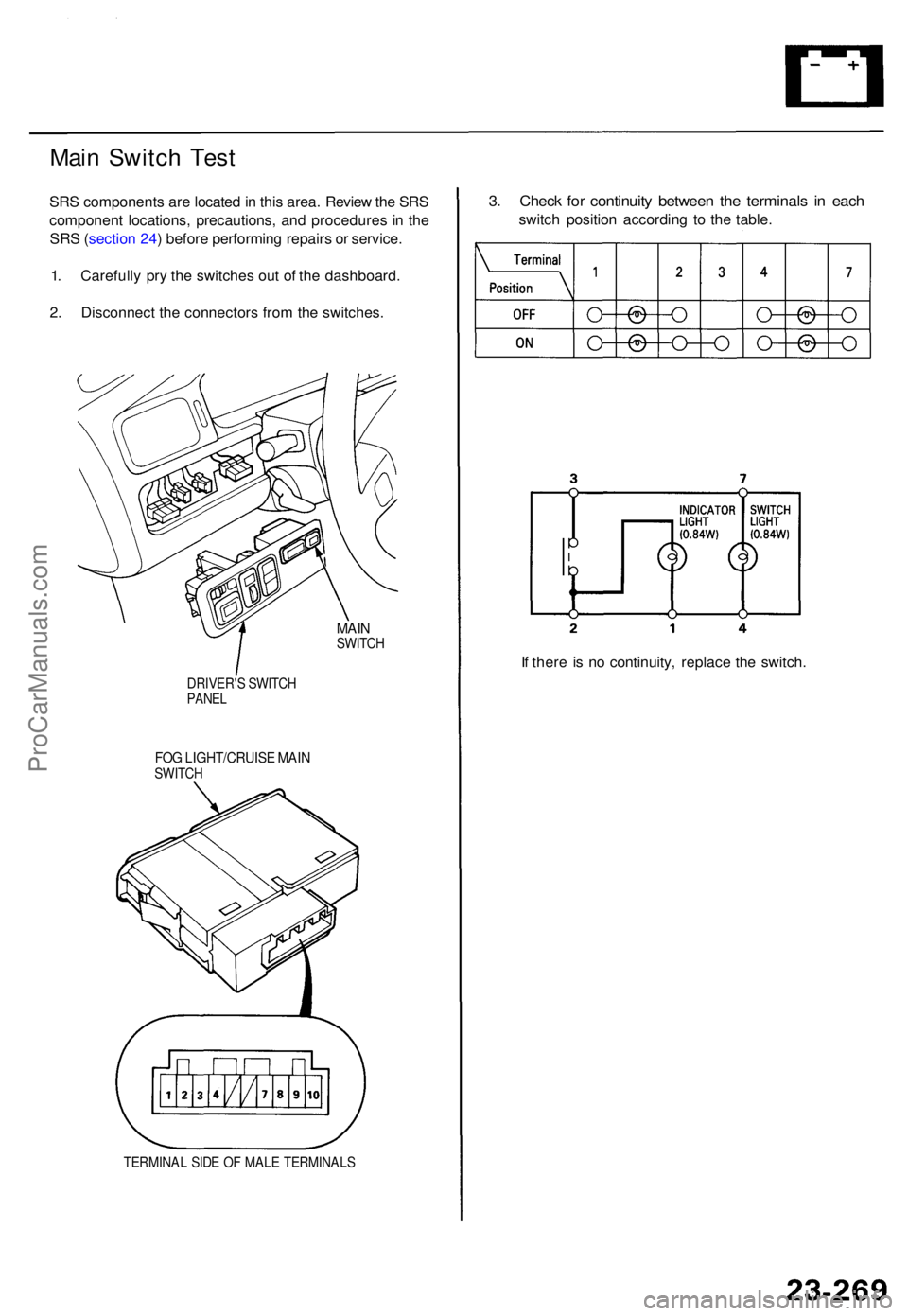
1 . Carefull y pr y th e switche s ou t o f th e dashboard .
2 . Disconnec t th e connector s fro m th e switches .
MAINSWITC H
DRIVER' S SWITC H
PANEL
FOG LIGHT/CRUIS E MAI NSWITC H
TERMINA L SID E O F MAL E TERMINAL S
3. Chec k fo r continuit y betwee n th e terminal s i n eac h
switc h positio n accordin g t o th e table .
I f ther e i s n o continuity , replac e th e switch .
ProCarManuals.com
Page 1728 of 1771
Security Alar m Syste m
Descriptio n
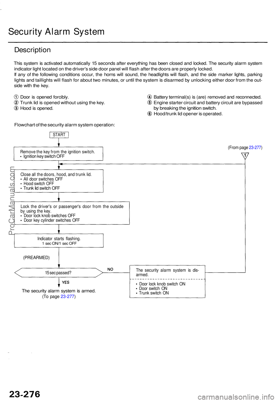
This syste m is activate d automaticall y 1 5 second s afte r everythin g ha s bee n close d an d locked . Th e securit y alar m syste m
indicato r ligh t locate d o n th e driver' s sid e doo r pane l wil l flas h afte r th e door s ar e properl y locked .
I f an y o f th e followin g condition s occur , th e horn s wil l sound , th e headlight s wil l flash , an d th e sid e marke r lights , parkin g
light s an d taillight s wil l flas h fo r abou t tw o minutes , o r unti l th e syste m is disarme d b y unlockin g eithe r doo r fro m th e out -
sid e wit h th e key .
Doo r i s opene d forcibly .
Trun k li d is opene d withou t usin g th e key .
Hoo d is opened . Batter
y terminal(s ) i s (are ) remove d an d reconnected .
Engin e starte r circui t an d batter y circui t ar e bypasse d
by breakin g th e ignitio n switch .
Hood/trun k li d opene r i s operated .
Flowchar t o f th e securit y alar m syste m operation :
START
Remov e th e ke y fro m th e ignitio n switch .Ignition ke y switc h OF F
(Fro m pag e 23-277 )
Clos e al l th e doors , hood , an d trun k lid .
Al l doo r switche s OF F
Hoo d switc h OF F
Trun k li d switc h OF F
Loc k th e driver' s o r passenger' s doo r fro m th e outsid e
b y usin g th e key .
Doo r loc k kno b switche s OF F
Doo r ke y cylinde r switche s OF F
Indicato r start s flashing .
1 se c ON/ 1 sec OF F
(PREARMED )
15 se c passed ?
The securit y alar m syste m is armed .
(To pag e 23-277 )
The securit y alar m syste m is dis -
armed .
Doo r loc k kno b switc h O N
Doo r switc h O N
Trun k switc h O N
ProCarManuals.com
Page 1729 of 1771
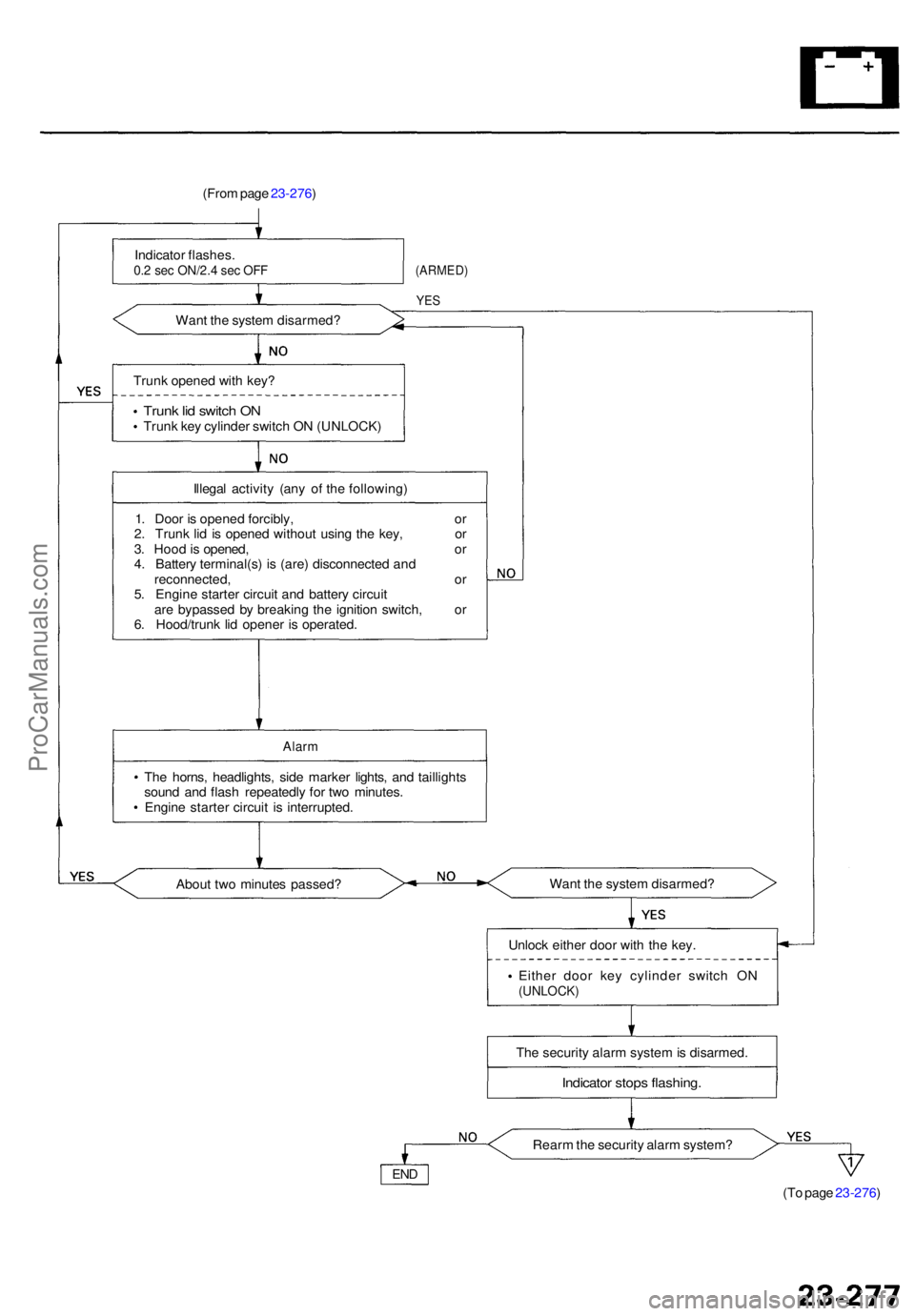
(From pag e 23-276 )
Indicato r flashes .
0.2 se c ON/2. 4 se c OF F
Wan t th e syste m disarmed ?
(ARMED)
YES
Trun k opene d wit h key ?
Trun k li d switc h O NTrun k ke y cylinde r switc h O N (UNLOCK )
Illega l activit y (an y o f th e following )
1 . Doo r i s opene d forcibly , o r
2 . Trun k li d i s opene d withou t usin g th e key , o r
3 . Hoo d is opened , o r
4 . Batter y terminal(s ) i s (are ) disconnecte d an d
reconnected , o r
5 . Engin e starte r circui t an d batter y circui t
ar e bypasse d b y breakin g th e ignitio n switch , o r
6 . Hood/trun k li d opene r i s operated .
Alarm
The horns , headlights , sid e marke r lights , an d taillight s
soun d an d flas h repeatedl y fo r tw o minutes .
Engin e starte r circui t i s interrupted .
Abou t tw o minute s passed ? Wan
t th e syste m disarmed ?
Unloc k eithe r doo r wit h th e key .
Eithe r doo r ke y cylinde r switc h O N
(UNLOCK )
The securit y alar m syste m is disarmed.
Indicato r stop s flashing .
Rearm th e securit y alar m system ?
(To pag e 23-276 )
END
ProCarManuals.com
Page 1746 of 1771
Steering-related Precautions
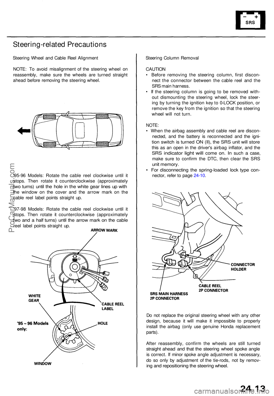
Steering Whee l an d Cabl e Ree l Alignmen t
NOTE : T o avoi d misalignmen t o f th e steerin g whee l o n
reassembly , mak e sur e th e wheel s ar e turne d straigh t
ahea d befor e removin g th e steerin g wheel .
'95-9 6 Models : Rotat e th e cabl e ree l clockwis e unti l i t
stops . The n rotat e i t counterclockwis e (approximatel y
two turns ) unti l th e hol e in th e whit e gea r line s u p wit h
the windo w o n th e cove r an d th e arro w mar k o n th e
cabl e ree l labe l point s straigh t up .
'97-9 8 Models : Rotat e th e cabl e ree l clockwis e unti l i t
stops . The n rotat e i t counterclockwis e (approximatel y
two an d a hal f turns ) unti l th e arro w mar k o n th e cabl e
reel labe l point s straigh t up . Steerin
g Colum n Remova l
CAUTIO N
• Befor e removin g th e steerin g column , firs t discon -
nec t th e connecto r betwee n th e cabl e ree l an d th e
SR S mai n harness .
• I f th e steerin g colum n i s goin g t o b e remove d with -
ou t dismountin g th e steerin g wheel , loc k th e steer -
in g b y turnin g th e ignitio n ke y to 0-LOC K position , o r
remov e th e ke y fro m th e ignitio n s o tha t th e steerin g
whee l wil l no t turn .
NOTE :
• Whe n th e airba g assembl y an d cabl e ree l ar e discon -
nected , an d th e batter y i s reconnecte d an d th e igni -
tion switc h is turne d O N (II) , th e SR S uni t wil l stor e
this a s a n ope n i n th e driver' s airba g inflator , an d th e
SR S indicato r light will com e on. I n suc h a case ,
mak e sur e t o confir m th e DTC , the n clea r th e SR S
unit memory .
• Fo r disconnectin g th e spring-loade d loc k typ e con -
nector , refe r t o pag e 24-10 .
D o no t replac e th e origina l steerin g whee l wit h an y othe r
design , becaus e i t wil l mak e i t impossibl e t o properly
instal l th e airba g (onl y us e genuin e Hond a replacemen t
parts) .
Afte r reassembly , confir m th e wheel s ar e stil l turne d
straight ahea d an d tha t th e steerin g whee l spok e angl e
is correct . I f mino r spok e angl e adjustment is necessary ,
d o s o onl y b y adjustmen t o f th e tie-rods , no t b y remov -
ing an d repositionin g th e steerin g wheel .
ProCarManuals.com
Page 1752 of 1771
Troubleshooting - '95-9 6 Model s
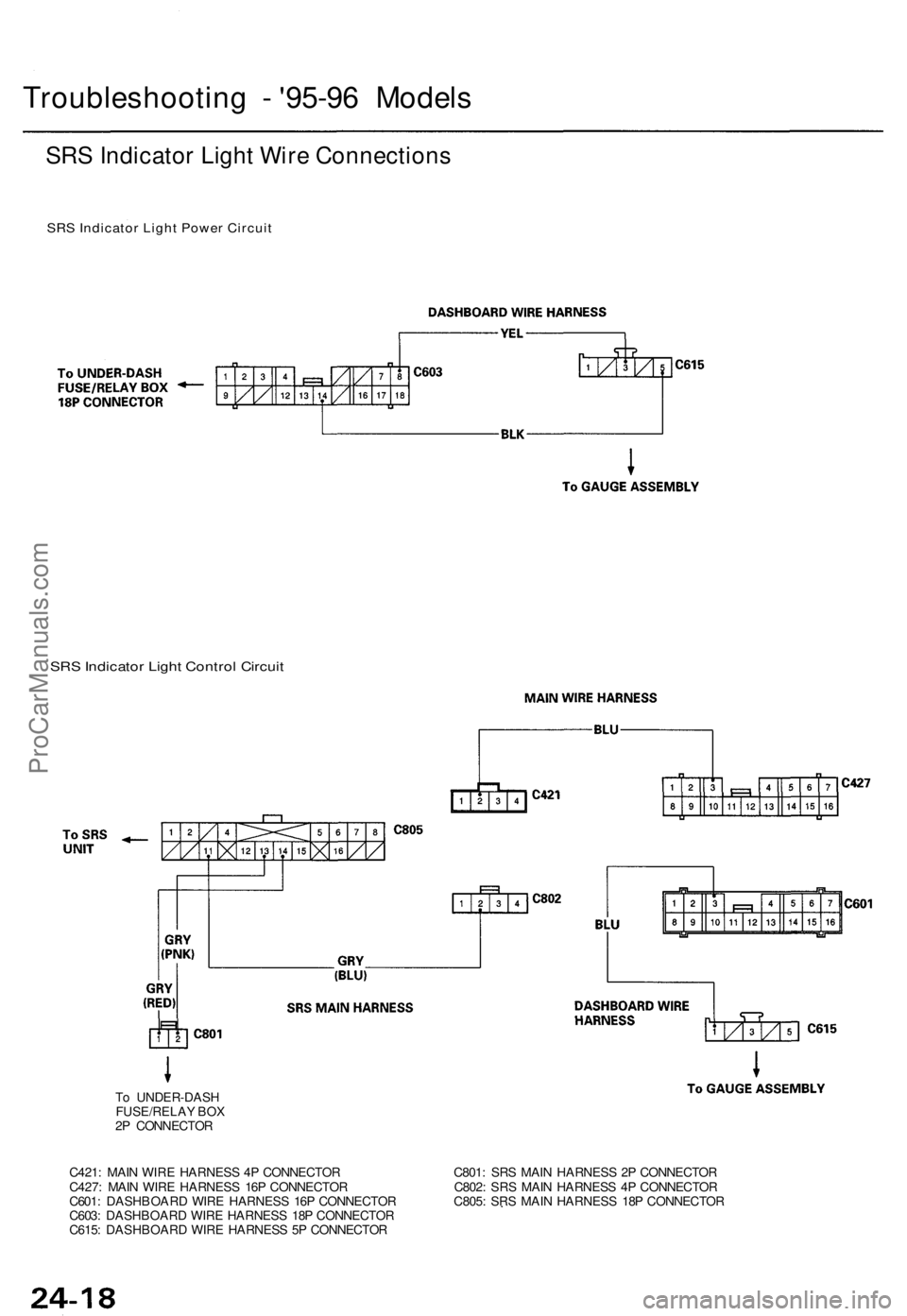
SRS Indicato r Ligh t Wir e Connection s
SRS Indicator Light Power Circuit
SRS Indicato r Ligh t Contro l Circui t
To UNDER-DAS H
FUSE/RELA Y BO X
2 P CONNECTO R
C421 : MAI N WIR E HARNES S 4 P CONNECTO R C801 : SR S MAI N HARNES S 2 P CONNECTO R
C427 : MAI N WIR E HARNES S 16 P CONNECTO R C802 : SR S MAI N HARNES S 4 P CONNECTO R
C601 : DASHBOAR D WIR E HARNES S 16 P CONNECTO R C805 : SR S MAI N HARNES S 18 P CONNECTO R
C603 : DASHBOAR D WIR E HARNES S 18 P CONNECTO R
C615 : DASHBOAR D WIR E HARNES S 5 P CONNECTO R
ProCarManuals.com
Page 1756 of 1771
Erasing th e DT C Memor y
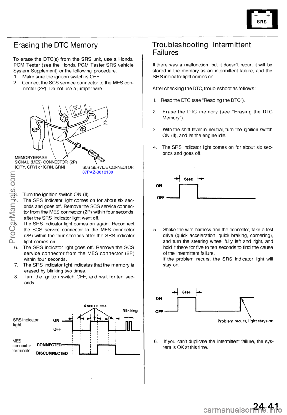
To eras e th e DTC(s ) fro m th e SR S unit , us e a Hond a
PGM Teste r (se e th e Hond a PG M Teste r SR S vehicl e
Syste m Supplement ) o r th e followin g procedure .
1. Mak e sur e th e ignitio n switc h is OFF .
2. Connec t th e SC S servic e connecto r t o th e ME S con -
necto r (2P) . D o no t us e a jumpe r wire .
MEMOR Y ERAS E
SIGNA L (MES ) CONNECTO R (2P )
[GRY , GRY ] or [GRN , GRN ]SCS SERVIC E CONNECTO R07PAZ-001010 0
3. Tur n th e ignitio n switc h O N (II) .
4. Th e SR S indicato r ligh t come s o n fo r abou t si x sec -
ond s an d goe s off . Remov e th e SC S servic e connec -
tor fro m th e ME S connecto r (2P ) withi n fou r second s
after th e SR S indicato r ligh t wen t off .
5 . Th e SR S indicato r ligh t come s o n again . Reconnec t
th e SC S servic e connecto r t o th e ME S connecto r
(2P ) withi n th e fou r second s afte r th e SR S indicato r
ligh t come s on .
6. Th e SR S indicato r ligh t goe s off . Remov e th e SC S
servic e connecto r fro m th e ME S connecto r (2P )
withi n fou r seconds .
7. Th e SR S indicato r ligh t indicate s tha t th e memor y is
erase d b y blinkin g tw o times .
8 . Tur n th e ignitio n switc h OFF , an d wai t fo r te n sec -
onds .
SRS indicato rlight
MESconnecto rterminals
5. Shak e th e wir e harnes s an d th e connector , tak e a tes t
driv e (quic k acceleration , quic k braking , cornering) ,
an d tur n th e steerin g whee l full y lef t an d right , an d
hold it ther e fo r fiv e to te n second s to fin d th e caus e
of th e intermitten t failure .
I f th e proble m recurs , th e SR S indicato r ligh t wil l
sta y on .
6 . I f yo u can' t duplicat e th e intermitten t failure , th e sys -
te m is O K a t thi s time .
Troubleshootin g Intermitten t
Failures
If ther e wa s a malfunction , bu t i t doesn' t recur , i t wil l b e
store d i n th e memor y a s a n intermitten t failure, and th e
SR S indicato r ligh t come s on .
Afte r checkin g th e DTC , troubleshoo t a s follows :
1 . Rea d th e DT C (se e "Readin g th e DTC") .
2 . Eras e th e DT C memor y (se e "Erasin g th e DT C
Memory") .
3 . Wit h th e shif t leve r i n neutral , tur n th e ignitio n switc h
O N (II) , an d le t th e engin e idle .
4 . Th e SR S indicato r ligh t come s o n fo r abou t si x sec -
ond s an d goe s off .
ProCarManuals.com