Page 1634 of 1771

SRS component s ar e locate d i n thi s area . Revie w th e SR S componen t locations , precautions , an d procedure s")
Lighting Syste m
Daytim e Runnin g Light s Contro l Uni t Inpu t Tes t (Canada )
SRS component s ar e locate d i n thi s area . Revie w th e SR S componen t locations , precautions , an d procedure s i n th e SR S
(sectio n 24 ) befor e performin g repair s o r service .
1. Remov e th e dashboar d lowe r cove r an d kne e bolste r (se e pag e 23-64 ).
2 . Disconnec t th e 14 P connecto r fro m th e contro l unit .
3 . Inspec t th e connecto r an d socke t terminal s t o b e sur e the y ar e al l makin g goo d contact .
I f th e terminal s ar e bent , loos e o r corroded , repai r the m a s necessary , an d rechec k th e system .
I f th e terminal s loo k OK , mak e th e followin g inpu t test s a t th e connector .
— If an y tes t indicate s a problem , fin d an d correc t th e cause , the n rechec k th e system .
— If al l th e inpu t test s prov e OK , th e contro l uni t mus t b e faulty ; replac e it .
RED/BL U
DAYTIM E RUNNIN G LIGHT SCONTRO L UNI T
14P CONNECTO R
WIRE SID E O FFEMAL E TERMINAL S
ProCarManuals.com
Page 1636 of 1771

Lighting Syste m
Front Parkin g Ligh t
Combinatio n Ligh t Switc h
Replacemen t
SRS component s ar e locate d i n thi s area . Revie w th e
SR S componen t locations , precautions , an d procedure s
i n th e SR S (sectio n 24 ) befor e performin g repair s o r ser -
vice .
1. Remov e th e dashboar d lowe r cove r an d kne e bol -
ste r (se e pag e 23-64 ).
2 . Remov e th e steerin g colum n covers .
STEERIN G COLUM NUPPER COVE R
Bulb Replacemen t
STEERINGCOLUMNLOWER
COVE R
3. Disconnec t th e connecto r fro m th e combinatio n
ligh t switch , the n remov e th e tw o screw s an d th e
switch .
COMBINATIO N LIGH T SWITC H
4. Instal l th e combinatio n ligh t switc h i n th e revers e
orde r o f removal . 1
. Remov e th e maintenanc e cove r an d inne r cove r
(lef t fron t parkin g light) , the n disconnec t th e 2 P con -
necto r fro m th e light .
2 . Tur n th e bul b socke t 45 ° counterclockwise , remov e
i t fro m th e ligh t housing , the n replac e th e bulb .
HEADLIGH TMAINTENANC ECOVER
INNERCOVE R
HEADLIGH T
ASSEMBL Y
BUL B (5 W )
2 P CONNECTO R
BUL
B SOCKE T
ProCarManuals.com
Page 1637 of 1771

Headlights
Replacemen t
CAUTION: Haloge n headlight s becom e ver y ho t i n use ;
d o no t touc h the m o r th e attachin g hardwar e immedi -
atel y afte r the y hav e bee n turne d off .
1 . Remov e th e fron t bumpe r (se e sectio n 20 ).
2 . Remov e th e headligh t maintenanc e cove r (lef t
headlight) , the n disconnec t th e 2 P an d 3 P connec -
tors .
3 . Remov e th e mountin g bolts , the n remov e th e head -
light assembly .
MOUNTIN GBOLTS
3P CONNECTO R
2P CONNECTO R
2 P CONNECTO R
HEADLIGHT
ASSEMBL Y
MOUNTING BOLT S
4. Instal l th e headligh t i n th e revers e orde r o f removal .
5 . Afte r replacement , adjus t th e headlight s t o loca l
requirement s (se e pag e 23-168 ).
Bul b Replacemen t
CAUTION:
Haloge n headlight s becom e ver y ho t i n use ; d o no t
touc h the m o r th e attachin g hardwar e immediatel y
afte r the y hav e bee n turne d off .
D o no t tr y t o replac e o r clea n th e headlight s wit h th e
light s on .
D o no t touc h th e glas s o f th e haloge n bulbs .
1 . Remov e th e headligh t maintenanc e cove r (lef t
headlight) , the n disconnec t th e 3 P connecto r fro m
th e headlight .
2 . Remov e th e rubbe r cap .
3 . Pul l th e retainin g sprin g awa y fro m th e bulb , the n
remov e th e bulb .
RUBBE R CA P
3 P CONNECTO R
HEADLIGH T
BULB(60/5 5 W )
4. Afte r replacement , adjus t th e headlight s t o loca l
requirement s (se e pag e 23-168 ).
ProCarManuals.com
Page 1638 of 1771
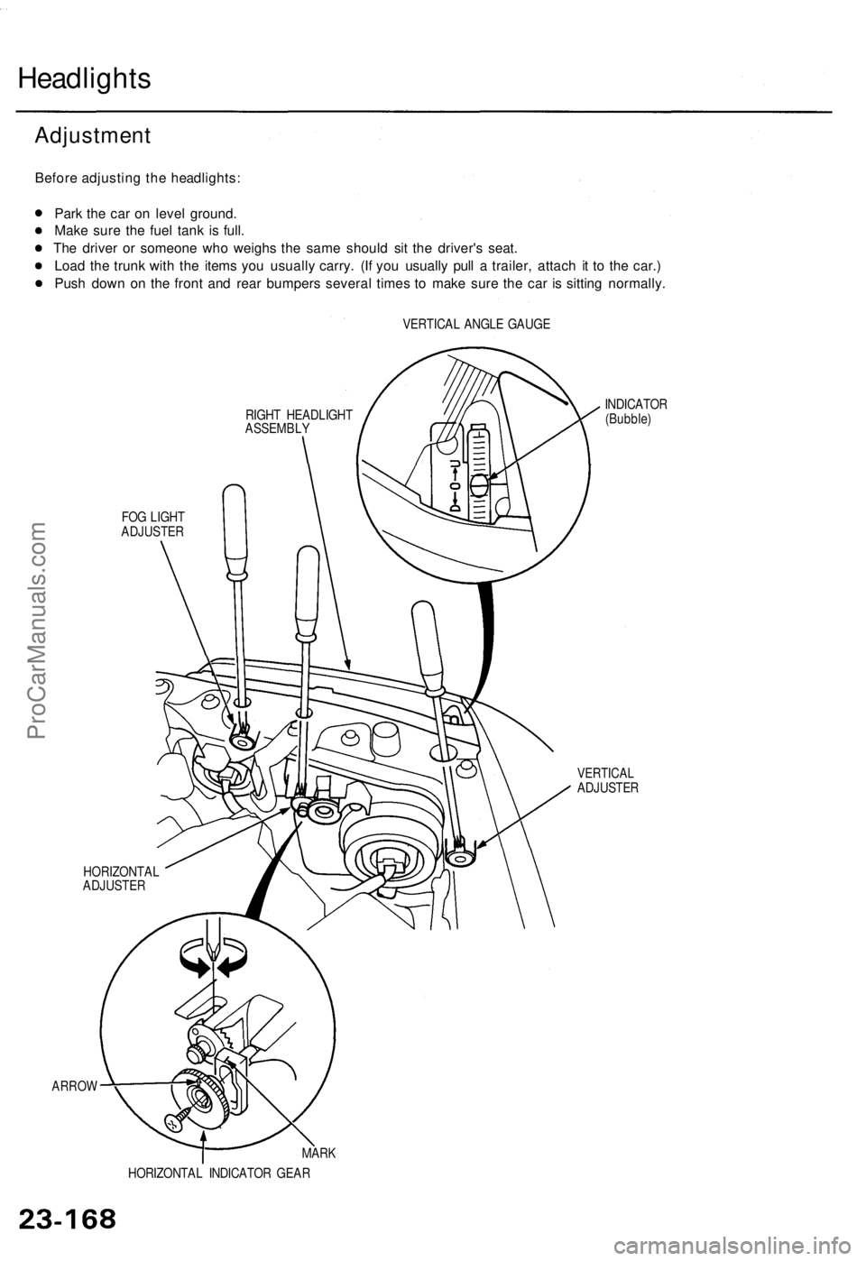
Headlights
Before adjustin g th e headlights :
Par k th e ca r o n leve l ground .
Mak e sur e th e fue l tan k i s full .
Th e drive r o r someon e wh o weigh s th e sam e shoul d si t th e driver' s seat .
Loa d th e trun k wit h th e item s yo u usuall y carry . (I f yo u usuall y pul l a trailer , attac h i t t o th e car. )
Pus h dow n o n th e fron t an d rea r bumper s severa l time s t o mak e sur e th e ca r i s sittin g normally .
VERTICAL ANGL E GAUG E
RIGH T HEADLIGH T
ASSEMBL Y
FO G LIGH T
ADJUSTE R
ARROW
INDICATO R
(Bubble )
VERTICA LADJUSTE R
HORIZONTA L
ADJUSTE R
MARK
HORIZONTA L INDICATO R GEA R
Adjustmen t
ProCarManuals.com
Page 1639 of 1771

CAUTION: Haloge n headlight s becom e ver y ho t i n use ;
d o no t touc h the m o r th e attachin g hardwar e immedi -
atel y afte r the y hav e bee n turne d off .
1 . Ope n th e hood .
2.Chec k th e horizonta l adjustmen t indicator .
Th e "0 " mar k o n th e horizonta l indicato r gea r shoul d
b e aligne d wit h th e mar k o n th e horizonta l indicator .
NOTE : Th e illustratio n show s th e righ t sid e adjuster .
MARK
HORIZONTA L INDICATO RGEAR
N
3.
4 .
HORIZONTA L INDICATO R
Check th e vertica l adjustmen t indicator . Th e bubbl e
shoul d b e centere d underneat h th e longes t scrib e
mar k o n th e gauge .
I f eithe r indicato r i s no t aligne d wit h it s "O " mar k a s
describe d above , a n adjustmen t ca n b e mad e b y
usin g a Phillip s screwdriver .
VERTICAL INDICATOR :
5. Adjus t th e headlight s t o loca l requirement s b y turn -
in g th e adjusters .
6 . Afte r headligh t replacement , i t ma y b e necessar y t o
readjus t th e horizonta l indicator gear.
Firs t instal l th e headlight , an d adjus t it s horizon -
ta l an d vertica l aiming s accordin g t o loca l
requirements .
The n chec k tha t th e arro w o n th e horizonta l indi -
cato r gea r i s aligne d wit h th e mar k o n th e hori -
zonta l indicator .
— If the y ar e no t aligned , remov e th e screw ,
adjus t th e indicato r gear , an d retighte n th e
screw .
NOTE: As the outer lenses are made of an acrylic coated,
polycarbonat e material , d o no t cove r th e headlight s
whe n the y ar e turne d on .
HORIZONTA L INDICATOR :
SCREW
MARK
ARRO W
HORIZONTA LINDICATORGEAR
INDICATO R (Bubble )
ProCarManuals.com
Page 1640 of 1771
 befor e performin g repair")
Fog Ligh t
Switc h Tes t
SRS component s ar e locate d i n thi s area . Revie w th e
SR S componen t locations , precautions , an d procedure s
i n th e SR S (sectio n 24 ) befor e performin g repair s o r ser -
vice .
1 . Remov e th e fo g ligh t switc h (se e pag e 23-269 ).
2 . Chec k fo r continuit y betwee n th e terminal s i n eac h
switc h positio n accordin g t o th e table .
Bulb Replacemen t
FOG LIGHT /
CRUIS E MAI N
SWITC H
TERMINA L SID E O FMAL E TERMINAL S
CAUTION:
Halogen headlight s becom e ver y ho t i n use ; d o no t
touc h the m o r th e attachin g hardwar e immediatel y
afte r the y hav e bee n turne d off .
D o no t tr y to replac e o r clea n th e headlight s wit h th e
light s on .
D o no t touc h th e glas s o f th e haloge n bulbs .
1 . Disconnec t th e 2 P connecto r fro m th e fo g light .
2 . Remov e th e rubbe r cap .
3 . Pul l th e retainin g sprin g awa y fro m th e bulb , the n
remov e th e bulb .
HEADLIGH T ASSEMBL Y
FO G LIGH T
BUL B (5 5 W ) RUBBE
R CA P
2 P CONNECTO R
4. Afte r replacement , adjus t th e headlight s t o loca l
requirement s (se e pag e 23-168 ).
ProCarManuals.com
Page 1641 of 1771
Front Tur n Signa l Light s Fron
t Sid e Marke rLights
Replacemen t
1. Remov e th e screw , an d pul l th e fron t tur n signa l
ligh t assembl y ou t o f th e fron t bumper .
FRONT TUR N
SIGNA L LIGH T
2P CONNECTO R
2. Disconnec t th e 2 P connecto r fro m th e light .
3. Tur n th e bul b socke t 45 ° counterclockwise , remov e
it fro m th e ligh t housing , the n replac e th e bulb .
BULB(21 W )
HOUSIN G
BULB SOCKE T
Replacemen t
1. Remov e th e screw , an d pul l th e fron t sid e marke r
light assembl y ou t o f th e fron t bumper .
FRONT SID E MARKE R LIGH T
2P CONNECTO R
2. Disconnec t th e 2 P connecto r fro m th e light .
3. Tur n th e bul b socke t 45 ° counterclockwise , remov e
i t fro m th e ligh t housing , the n replac e th e bulb .
HOUSIN GBULB(3CP)
BULB SOCKE T
ProCarManuals.com
Page 1642 of 1771
Taillights
Replacemen t
1. Ope n th e trun k lid , an d pul l bac k th e trun k sid e trim .
2. Disconnec t th e 8 P connecto r fro m th e tailligh t
assembly .
3. Remov e th e fou r mountin g nut s an d th e tailligh t
assembly .
GASKET
8P CONNECTO RTAILLIGHTASSEMBL Y
NOTE:
Inspect the gasket; replace it if it is distorted or stays
compressed .
After installin g them , ru n wate r ove r th e light s t o
mak e sur e the y d o no t leak .
Bulb Replacemen t
1. Ope n th e trun k lid , an d pul l bac k th e trun k sid e trim .
2 . Tur n th e bul b socke t 45 ° counterclockwise , remov e
it fro m th e tailligh t housing , the n replac e th e bulb .
BRAK E LIGHT/TAILLIGH T BUL B (21/ 5 W )
REA R SID E MARKE R LIGH T BUL B (3CP )
TURN SIGNA L LIGH T BUL B (2 1 W )
BACK-U P LIGH T BUL B (2 1 W )
ProCarManuals.com