Page 1455 of 1771
Trunk Li d
Adjustmen t
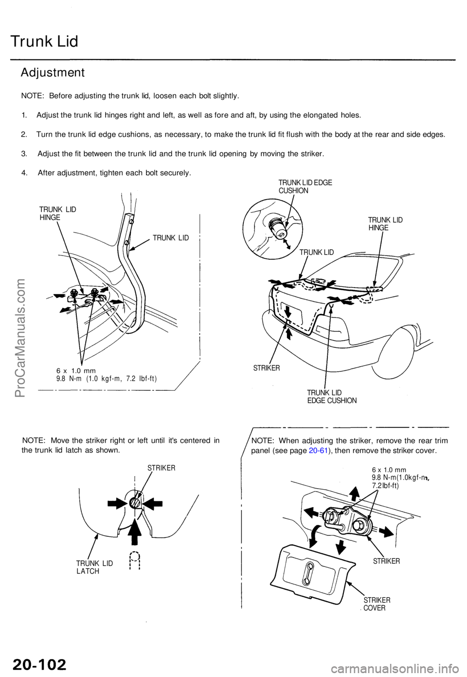
NOTE: Befor e adjustin g th e trun k lid , loose n eac h bol t slightly .
1 . Adjus t th e trun k li d hinge s righ t an d left , a s wel l a s for e an d aft , b y usin g th e elongate d holes .
2 . Tur n th e trun k li d edg e cushions , a s necessary , t o mak e th e trun k li d fi t flus h wit h th e bod y a t th e rea r an d sid e edges .
3 . Adjus t th e fi t betwee n th e trun k li d an d th e trun k li d openin g b y movin g th e striker .
4 . Afte r adjustment , tighte n eac h bol t securely .
TRUNK LI D EDG E
CUSHIO N
TRUNK LI DHING E
TRUNK LI D
6 x 1. 0 m m9.8 N- m (1. 0 kgf-m , 7. 2 Ibf-ft )
STRIKE R
TRUNK LI D
HING E
TRUN K LI D
EDG E CUSHIO N
NOTE: Mov e th e strike r righ t o r lef t unti l it' s centere d i n
th e trun k li d latc h a s shown .
STRIKE R
TRUNK LI DLATC H
NOTE: Whe n adjustin g th e striker , remov e th e rea r tri m
pane l (se e pag e 20-61 ), the n remov e th e strike r cover .
6 x 1. 0 m m9.8 N-m(1.0kgf- n7.2 Ibf-ft )
STRIKE RCOVER
STRIKE R
TRUNK LI D
ProCarManuals.com
Page 1463 of 1771
Door Moldings
Installation
1. Glue the new adhesive tape to the moldings as
shown.
FRONT DOOR MOLDING
CLIP
DOOR MOLDING
NEW ADHESIVE TAPE
Thickness: 1.2 mm (0.05 in)
5 mm
(0.2
in)
2. Install the clips on the molding.
3. Heat the bonding surface of the door and door mold-
ing with an infrared dryer.
Door: 104- 140°F (40-60°C)
Molding: 68 - 86°F (20 - 30°C)
NOTE: Use care when heating to prevent deforma-
tion of the molding.
4. Align the molding with the clip locations and set the
molding. Lightly push on the molding until its edge
is fully seated on the adhesive tape.
NOTE: Do not spray water on the molding within
the first 24 hours after installation.
5. Reassemble all removed parts.
REAR DOOR MOLDING
CLIPProCarManuals.com
Page 1486 of 1771
Rear Windo w
Installatio n (cont'd )
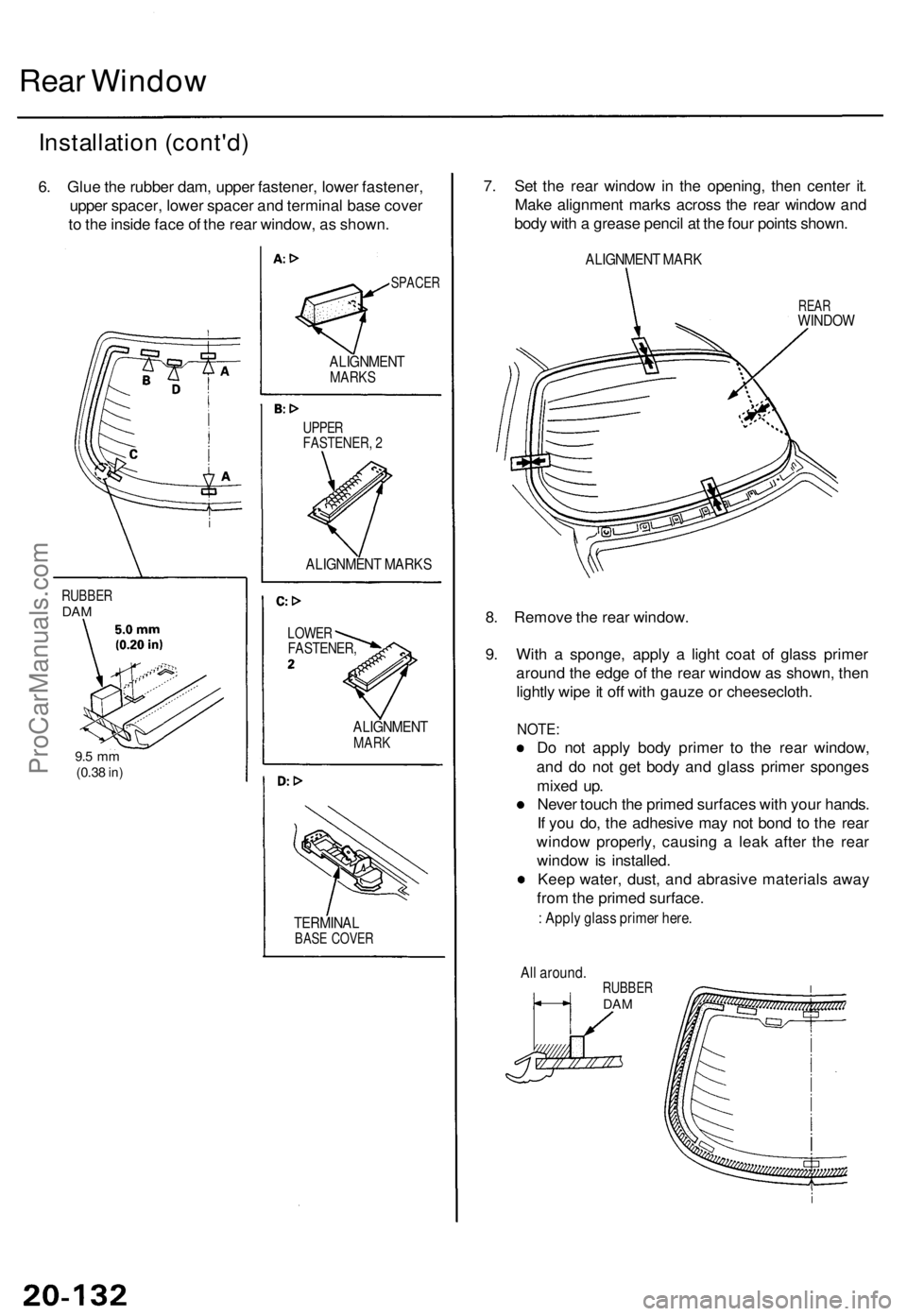
6. Glu e th e rubbe r dam , uppe r fastener , lowe r fastener ,
uppe r spacer , lowe r space r an d termina l bas e cove r
t o th e insid e fac e o f th e rea r window , a s shown .
RUBBE RDAM
9.5 m m(0.3 8 in)
SPACE R
ALIGNMEN TMARKS
UPPERFASTENER , 2
ALIGNMEN T MARK S
LOWERFASTENER ,
ALIGNMENTMARK
TERMINA LBASE COVE R
7. Se t th e rea r windo w in th e opening , the n cente r it .
Mak e alignmen t mark s acros s th e rea r windo w an d
bod y wit h a greas e penci l a t th e fou r point s shown .
ALIGNMEN T MAR K
REARWINDO W
8. Remov e th e rea r window .
9 . Wit h a sponge , appl y a ligh t coa t o f glas s prime r
aroun d th e edg e o f th e rea r windo w a s shown , the n
lightl y wip e it of f wit h gauz e o r cheesecloth .
NOTE:
Do no t appl y bod y prime r t o th e rea r window ,
an d d o no t ge t bod y an d glas s prime r sponge s
mixe d up .
Neve r touc h th e prime d surface s wit h you r hands .
I f yo u do , th e adhesiv e ma y no t bon d t o th e rea r
windo w properly , causin g a lea k afte r th e rea r
windo w is installed .
Kee p water , dust , an d abrasiv e material s awa y
fro m th e prime d surface .
: Appl y glas s prime r here .
Al l around .
RUBBERDAM
ProCarManuals.com
Page 1487 of 1771
10.
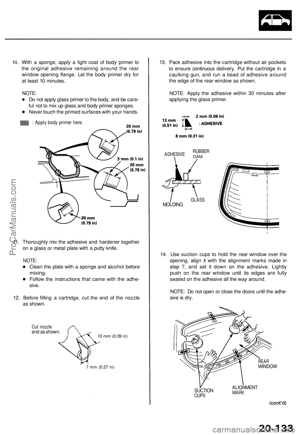
With a sponge, apply a light coat of body primer to
the original adhesive remaining around the rear
window opening flange. Let the body primer dry for
at least 10 minutes.
NOTE:
Do not apply glass primer to the body, and be care-
ful not to mix up glass and body primer sponges.
Never touch the primed surfaces with your hands.
: Apply body primer here.
11. Thoroughly mix the adhesive and hardener together
on a glass or metal plate with a putty knife.
NOTE:
Clean the plate with a sponge and alcohol before
mixing.
Follow the instructions that came with the adhe-
sive.
12. Before filling a cartridge, cut the end of the nozzle
as shown.
Cut nozzle
end as shown.
10 mm
(0.39
in)
7 mm
(0.27
in)
13. Pack adhesive into the cartridge without air pockets
to ensure continuous delivery. Put the cartridge in a
caulking gun, and run a bead of adhesive around
the edge of the rear window as shown.
NOTE: Apply the adhesive within 30 minutes after
applying the glass primer.
ADHESIVE
RUBBER
DAM
MOLDING
GLASS
14. Use suction cups to hold the rear window over the
opening, align it with the alignment marks made in
step 7, and set it down on the adhesive. Lightly
push on the rear window until its edges are fully
seated on the adhesive all the way around.
NOTE: Do not open or close the doors until the adhe-
sive is dry.
REAR
WINDOW
SUCTION
CUPS
ALIGNMENT
MARKProCarManuals.com
Page 1495 of 1771
Troubleshooting
Self-diagnosis Functio n
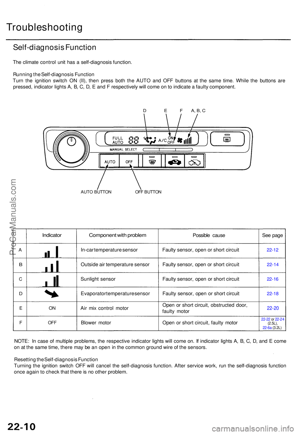
The climat e contro l uni t ha s a self-diagnosi s function .
Runnin g th e Self-diagnosi s Functio n
Tur n th e ignitio n switc h O N (II) , the n pres s bot h th e AUT O an d OF F button s a t th e sam e time . Whil e th e button s ar e
pressed , indicato r light s A , B , C , D , E an d F respectivel y wil l com e o n to indicat e a fault y component .
AUTO BUTTO NOFF BUTTO N
A
B
C
D
E
F
Indicator
ON
OF F
Componen t wit h proble m
In-car temperatur e senso r
Outsid e ai r temperatur e senso r
Sunligh t senso r
Evaporato r temperatur e senso r
Ai r mi x contro l moto r
Blowe r moto r Possibl
e caus e
Fault y sensor , ope n o r shor t circui t
Fault y sensor , ope n o r shor t circui t
Fault y sensor , ope n o r shor t circui t
Fault y sensor , ope n o r shor t circui t
Ope n o r shor t circuit , obstructe d door ,
fault y moto r
Ope n o r shor t circuit , fault y moto r Se
e pag e22-1 2
22-1 4
22-16
22-1 8
22-2 0
22-22 or 22- 24
(2.5L),
NOTE : I n cas e o f multipl e problems , th e respectiv e indicato r light s wil l com e on . I f indicato r light s A , B , C , D , an d E com e
o n a t th e sam e time , ther e ma y b e a n ope n in th e commo n groun d wir e o f th e sensors .
Resettin g th e Self-diagnosi s Functio n
Turnin g th e ignitio n switc h OF F wil l cance l th e self-diagnosi s function . Afte r servic e work , ru n th e self-diagnosi s functio n
onc e agai n to chec k tha t ther e is n o othe r problem.
D E F A, B , C
22-6a (3.2L)
ProCarManuals.com
Page 1504 of 1771
Sunlight Sensor
Replacement
1. Remove the sunlight sensor from the left tweeter
speaker grille, and disconnect the 2P connector.
NOTE: Be careful not to damage the left tweeter
speaker grille.
SUNLIGHT SENSOR
2. Install in the reverse order of removal.
Test
Turn the ignition switch ON (II). Measure the voltage
between the terminals with the (+) probe on the No. 1
terminal and the (-) probe on the No. 2 terminal with the
2P connector connected. Voltage should be;
3.7 ± 0.2 V or more with the sensor out of direct sun-
light.
3.6 ± 0.2 V or less with the sensor in direct sunlight.
NOTE: The voltage will not change under the light of a
flashlight or a fluorescent lamp.
SUNLIGHT SENSORProCarManuals.com
Page 1518 of 1771
A/C Syste m Servic e
Performanc e Tes t
The performanc e tes t wil l hel p determin e i f th e ai r con -
ditione r syste m is operatin g withi n specifications .
Us e onl y servic e equipmen t tha t i s U.L.-liste d an d is cer -
tifie d t o mee t th e requirement s o f SA E J221 0 t o remov e
HFC-134 a (R-134a ) fro m th e ai r conditione r system .
CAUTION : Exposur e t o ai r conditione r refrigeran t an d
lubrican t vapo r o r mis t ca n irritat e eyes , nos e an d
throat . Avoi d breathin g th e ai r conditione r refrigeran t
an d lubrican t vapo r o r mist .
I f accidenta l syste m discharg e occurs , ventilat e wor k
are a befor e resumin g service .
R-134 a servic e equipmen t o r vehicl e ai r conditione r sys -
tem s shoul d no t b e pressur e teste d o r lea k teste d wit h
compresse d air .
Som e mixture s o f ai r an d R-134 a hav e bee n
show n to b e combustibl e a t elevate d pressure s an d ca n
resul t i n fir e o r explosio n causin g injur y o r propert y
damage . Neve r us e compresse d ai r t o pressur e tes t R -
134 a servic e equipmen t o r vehicl e ai r conditione r sys -
tems .
Additiona l healt h an d safet y informatio n ma y b e obtaine d
from th e refrigeran t an d lubrican t manufacturers .
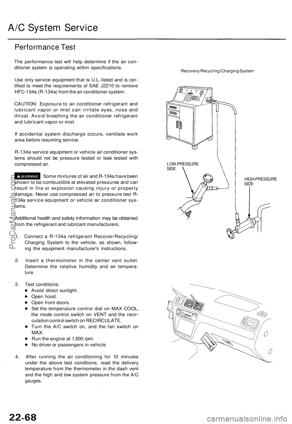
1 . Connec t a R-134 a refrigeran t Recover/Recycling /
Chargin g Syste m to th e vehicle , a s shown , follow -
in g th e equipmen t manufacturer' s instructions .
2 . Inser t a thermomete r i n th e cente r ven t outlet .
Determin e th e relativ e humidit y an d ai r tempera -
ture .
Recovery/Recycling/Chargin g Syste m
HIGH-PRESSUR ESIDE
3. Tes t conditions :
Avoi d direc t sunlight .
Ope n hood .
Ope n fron t doors .
Se t th e temperatur e contro l dia l o n MA X COOL ,
th e mod e contro l switc h o n VEN T an d th e recir -
culatio n contro l switc h o n RECIRCULATE .
Tur n th e A/ C switc h on , an d th e fa n switc h o n
MAX .
Run th e engin e a t 1,50 0 rpm .
N o drive r o r passenger s in vehicl e
4 . Afte r runnin g th e ai r conditionin g fo r 1 0 minute s
unde r th e abov e tes t conditions , rea d th e deliver y
temperatur e fro m th e thermomete r i n th e das h ven t
an d th e hig h an d lo w syste m pressur e fro m th e A/ C
gauges .
LOW-PRESSUR ESIDE
ProCarManuals.com
Page 1538 of 1771
Five-step Troubleshooting
1. Verify The Complaint
Turn on all the components in the problem circuit to
verify the customer complaint. Note the symptoms.
Do not begin disassembly or testing until you have
narrowed down the problem area.
2. Analyze The Schematic
Look up the schematic for the problem circuit.
Determine how the circuit is supposed to work by
tracing the current paths from the power feed
through the circuit components to ground. If several
circuits fail at the same time, the fuse or ground is a
likely cause.
Based on the symptoms and your understanding of
the circuit operation, identify one or more possible
causes of the problem.
3. Isolate The Problem By Testing The Circuit
Make circuit tests to check the diagnosis you made
in step 2. Keep in mind that a logical, simple proce-
dure is the key to efficient troubleshooting. Test for
the most likely cause of failure first. Try to make
tests at points that are easily accessible.
4. Fix The Problem
Once the specific problem is identified, make the
repair. Be sure to use proper tools and safe proce-
dures.
5. Make Sure The Circuit Works
Turn on all components in the repaired circuit in all
modes to make sure you've fixed the entire prob-
lem. If the problem was a blown fuse, be sure to
test all of the circuits on the fuse. Make sure no new
problems turn up and the original problem does not
recur.
Wire Color Codes
The following abbreviations are used to identify wire
colors in the circuit schematics:
WHT .............................White
YEL ............................... Yellow
BLK .............................. Black
BLU
..............................
Blue
GRN ............................. Green
RED
..............................
Red
ORN ............................. Orange
PNK.............................. Pink
BRN .............................. Brown
GRY.............................. Gray
PUR .............................. Purple
LT BLU ......................... Light Blue
LT GRN ........................ Light Green
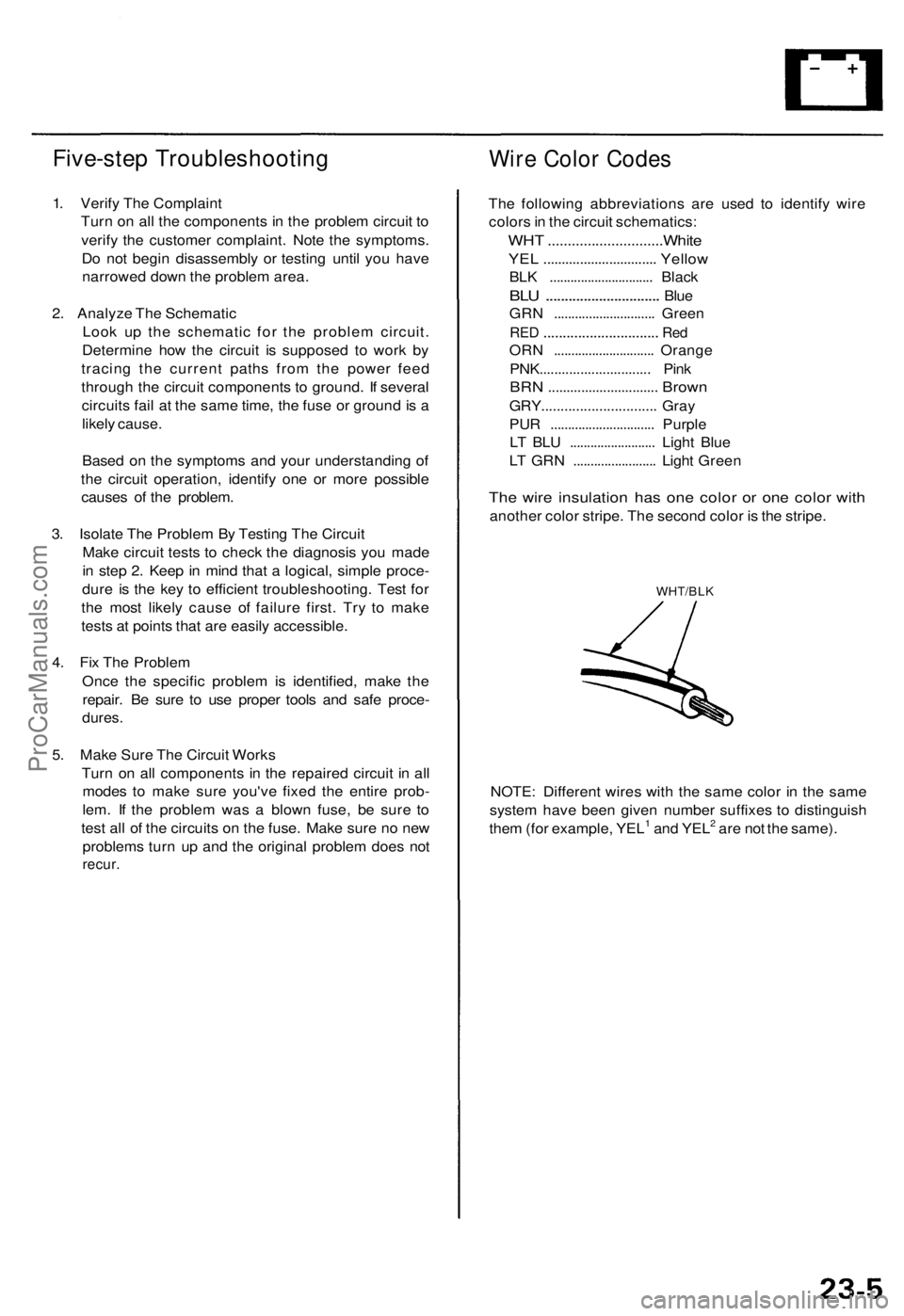
The wire insulation has one color or one color with
another color stripe. The second color is the stripe.
WHT/BLK
NOTE: Different wires with the same color in the same
system have been given number suffixes to distinguish
them (for example, YEL1 and YEL2 are not the same).ProCarManuals.com