1995 ACURA TL light
[x] Cancel search: lightPage 1305 of 1771
ABS Functio n Tes t
1. Rais e th e ca r of f th e ground , an d suppor t i t wit h safet y
stand s (se e sectio n 1 ).
2 . Chec k tha t ther e is n o brak e drag .
3 . Tur n th e ignitio n switc h O N (II) , an d confir m tha t th e
AB S indicato r ligh t come s on .
I f th e AB S indicato r ligh t doe s no t com e on , follo w
th e troubleshootin g o n pag e 19-60 .
4 . Hond a PG M Tester : Connec t th e PG M Teste r a s
describe d i n th e PG M Teste r Anti-Loc k Brak e
Syste m (ABS ) Vehicl e Syste m Supplement . Follo w
th e tester' s prompt s instea d o f step s 5 throug h 1 1
o f thi s procedure .
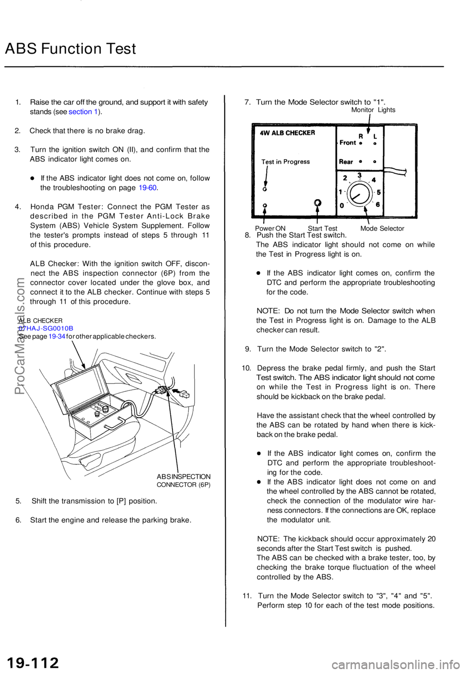
AL B Checker : Wit h th e ignitio n switc h OFF , discon -
nec t th e AB S inspectio n connecto r (6P ) fro m th e
connecto r cove r locate d unde r th e glov e box , an d
connec t i t t o th e AL B checker . Continu e wit h step s 5
throug h 1 1 o f thi s procedure .
ALB CHECKE R07HAJ-SG0010 BSee pag e 19-34 for othe r applicabl e checkers .
AB S INSPECTIO N
CONNECTO R (6P )
5. Shif t th e transmissio n t o [P ] position .
6 . Star t th e engin e an d releas e th e parkin g brake .
7. Tur n th e Mod e Selecto r switc h t o "1" .Monito r Light s
Power O N Star t Tes t Mod e Selecto r8. Pus h th e Star t Tes t switch .
Th e AB S indicato r ligh t shoul d no t com e o n whil e
th e Tes t i n Progres s ligh t i s on .
I f th e AB S indicato r ligh t come s on , confir m th e
DT C an d perfor m th e appropriat e troubleshootin g
fo r th e code .
NOTE : D o no t tur n th e Mod e Selecto r switc h whe n
the Tes t i n Progres s ligh t i s on . Damag e t o th e AL B
checke r ca n result .
9 . Tur n th e Mod e Selecto r switc h t o "2" .
10 . Depres s th e brak e peda l firmly , an d pus h th e Star t
Test switch . Th e AB S indicato r ligh t shoul d no t com e
on whil e th e Tes t i n Progres s ligh t i s on . Ther e
shoul d b e kickbac k o n th e brak e pedal .
Hav e th e assistan t chec k tha t th e whee l controlle d b y
th e AB S ca n b e rotate d b y han d whe n ther e i s kick -
bac k o n th e brak e pedal .
I f th e AB S indicato r ligh t come s on , confir m th e
DT C an d perfor m th e appropriat e troubleshoot -
in g fo r th e code .
I f th e AB S indicato r ligh t doe s no t com e o n an d
th e whee l controlle d b y th e AB S canno t b e rotated ,
chec k th e connectio n o f th e modulato r wir e har -
nes s connectors . I f th e connection s ar e OK , replac e
th e modulato r unit .
NOTE : Th e kickbac k shoul d occu r approximatel y 2 0
second s afte r th e Star t Tes t switc h is pushed .
Th e AB S ca n b e checke d wit h a brak e tester , too , b y
checkin g th e brak e torqu e fluctuatio n o f th e whee l
controlle d b y th e ABS .
11 . Tur n th e Mod e Selecto r switc h t o "3" , "4 " an d "5" .
Perfor m ste p 1 0 fo r eac h o f th e tes t mod e positions .
ProCarManuals.com
Page 1306 of 1771
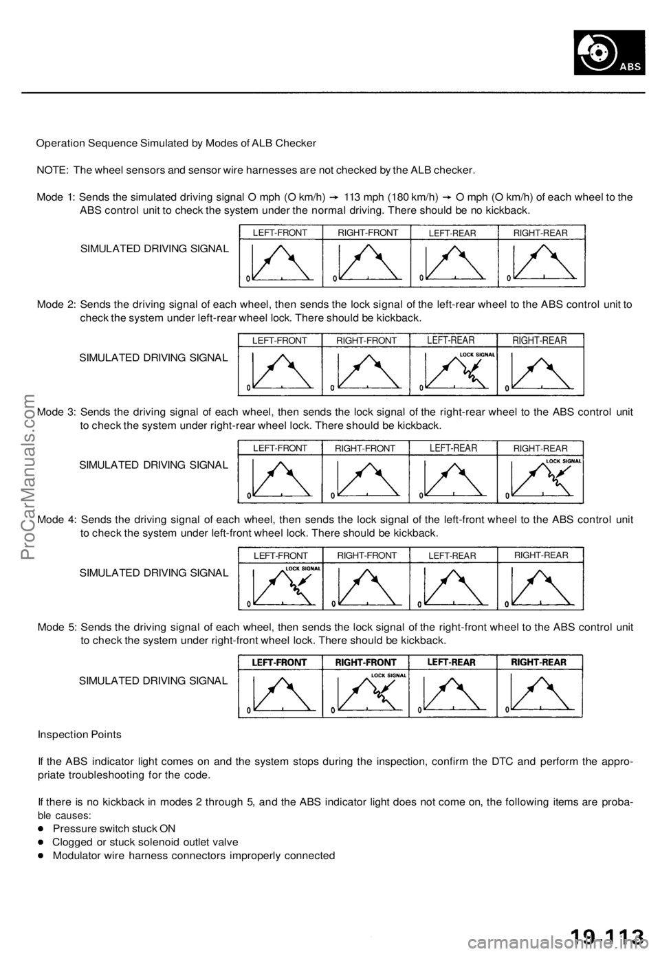
Operation Sequence Simulated by Modes of ALB Checker
NOTE: The wheel sensors and sensor wire harnesses are not checked by the ALB checker.
Mode 1: Sends the simulated driving signal O mph (O km/h) 113 mph (180 km/h) O mph (O km/h) of each wheel to the
ABS control unit to check the system under the normal driving. There should be no kickback.
SIMULATED DRIVING SIGNAL
LEFT-FRONT
RIGHT-FRONT
LEFT-REAR
RIGHT-REAR
Mode 2: Sends the driving signal of each wheel, then sends the lock signal of the left-rear wheel to the ABS control unit to
check the system under left-rear wheel lock. There should be kickback.
SIMULATED DRIVING SIGNAL
LEFT-FRONT
RIGHT-FRONT
LEFT-REAR
RIGHT-REAR
Mode 3: Sends the driving signal of each wheel, then sends the lock signal of the right-rear wheel to the ABS control unit
to check the system under right-rear wheel lock. There should be kickback.
SIMULATED DRIVING SIGNAL
LEFT-FRONT
RIGHT-FRONT
LEFT-REAR
RIGHT-REAR
Mode 4: Sends the driving signal of each wheel, then sends the lock signal of the left-front wheel to the ABS control unit
to check the system under left-front wheel lock. There should be kickback.
SIMULATED DRIVING SIGNAL
LEFT-FRONT
RIGHT-FRONT
LEFT-REAR
RIGHT-REAR
Mode 5: Sends the driving signal of each wheel, then sends the lock signal of the right-front wheel to the ABS control unit
to check the system under right-front wheel lock. There should be kickback.
SIMULATED DRIVING SIGNAL
Inspection Points
If the ABS indicator light comes on and the system stops during the inspection, confirm the DTC and perform the appro-
priate troubleshooting for the code.
If there is no kickback in modes 2 through 5, and the ABS indicator light does not come on, the following items are proba-
ble causes:
Pressure switch stuck ON
Clogged or stuck solenoid outlet valve
Modulator wire harness connectors improperly connectedProCarManuals.com
Page 1310 of 1771
Modulator Uni t
Brak e Flui d Replacement/Bleedin g (cont'd )
6. Star t th e engin e an d le t i t idl e fo r a minute . Sto p th e
engine .
7 . Chec k th e brak e flui d leve l i n th e reservoir . I t shoul d
b e belo w th e MA X (upper ) leve l line .
8 . Repea t th e step s 4 throug h 7 to drai n th e res t o f th e
brak e flui d fro m th e modulato r unit .
NOTE : Th e modulato r ha s a capacit y o f approximatel y
150 ( 5 fl-oz , 5. 3 Imp-oz) . Approximatel y 3 5 - 4 5
(1 1/6- 1 1/ 2 fl-oz , 1.2-1. 6 Imp-oz ) o f th e flui d i s
draine d a t eac h try .
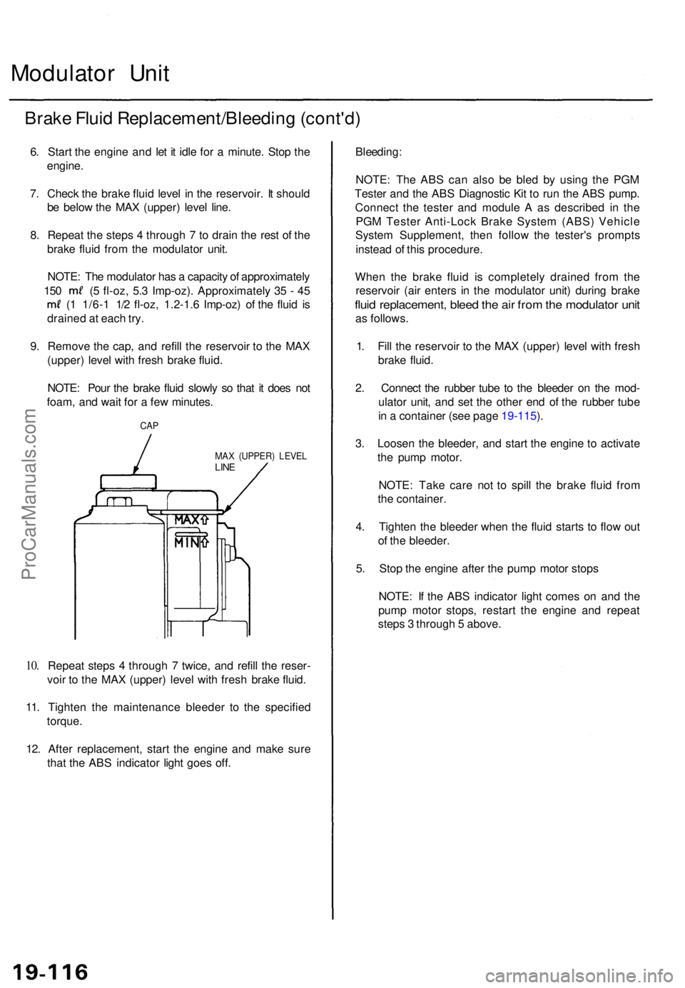
9 . Remov e th e cap , an d refil l th e reservoi r t o th e MA X
(upper ) leve l wit h fres h brak e fluid .
NOTE : Pou r th e brak e flui d slowl y s o tha t i t doe s no t
foam , an d wai t fo r a fe w minutes .
10.
CA P
MA X (UPPER ) LEVE LLINE
Repea t step s 4 throug h 7 twice , an d refil l th e reser -
voi r t o th e MA X (upper ) leve l wit h fres h brak e fluid .
11 . Tighten the maintenanc e bleede r t o th e specifie d
torque .
12 . Afte r replacement , star t th e engin e an d mak e sur e
tha t th e AB S indicator light goe s off .
Bleeding :
NOTE: Th e AB S ca n als o b e ble d b y usin g th e PG M
Teste r an d th e AB S Diagnosti c Ki t t o ru n th e AB S pump .
Connec t th e teste r an d modul e A as describe d i n th e
PG M Teste r Anti-Loc k Brak e Syste m (ABS ) Vehicl e
Syste m Supplement , the n follo w th e tester' s prompt s
instea d o f thi s procedure .
Whe n th e brak e flui d i s completel y draine d fro m th e
reservoi r (ai r enter s i n th e modulato r unit ) durin g brak e
fluid replacement , blee d th e ai r fro m th e modulato r uni t
as follows .
1 . Fil l th e reservoi r t o th e MA X (upper ) leve l wit h fres h
brak e fluid .
2 . Connec t th e rubbe r tub e t o th e bleede r o n th e mod -
ulato r unit , an d se t th e othe r en d o f th e rubbe r tub e
i n a containe r (se e page 19-115 ).
3 . Loose n th e bleeder , an d star t th e engin e t o activat e
th e pum p motor .
NOTE : Tak e car e no t t o spil l th e brak e flui d fro m
th e container .
4 . Tighte n th e bleede r whe n th e flui d start s t o flo w ou t
o f th e bleeder .
5 . Sto p th e engin e afte r th e pum p moto r stop s
NOTE : I f th e AB S indicato r ligh t come s o n an d th e
pum p moto r stops , restar t th e engin e an d repea t
step s 3 throug h 5 above .
ProCarManuals.com
Page 1322 of 1771
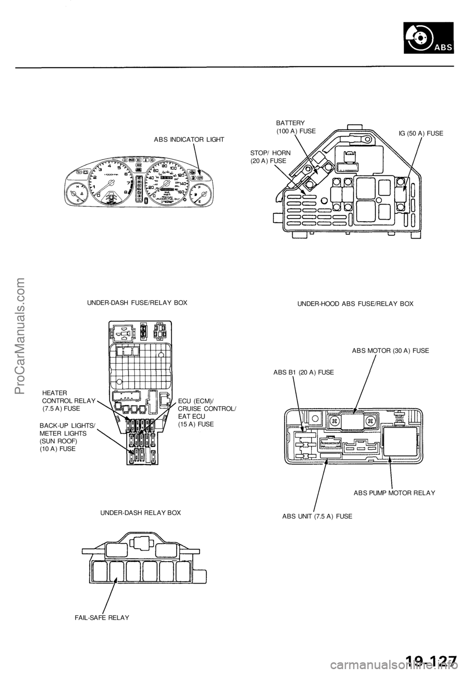
ABS INDICATOR LIGHT
BATTERY
(100 A) FUSE
STOP/ HORN
(20 A) FUSE
IG (50 A) FUSE
UNDER-DASH FUSE/RELAY BOX
UNDER-HOOD ABS FUSE/RELAY BOX
HEATER
CONTROL RELAY
(7.5 A) FUSE
BACK-UP LIGHTS/
METER LIGHTS
(SUN ROOF)
(10 A) FUSE
ECU (ECM)/
CRUISE CONTROL/
EAT ECU
(15 A) FUSE
ABS MOTOR (30 A) FUSE
ABS B1 (20 A) FUSE
UNDER-DASH RELAY BOX
ABS PUMP MOTOR RELAY
ABS UNIT (7.5 A) FUSE
FAIL-SAFE RELAYProCarManuals.com
Page 1330 of 1771
Troubleshooting Precautions
ABS Indicator Light
1. If the system is OK, the ABS indicator light goes off two seconds after turning the ignition switch ON (II) without start-
ing the engine. After starting the engine, the ABS indicator light comes on again and goes off after two seconds. This
occurs because the ABS control unit is activated by the IG2 power source.
2. The ABS indicator light comes on when the ABS control unit detects a problem in the system. However, even though
the system is normal, the ABS indicator light comes on, too, under the following conditions. To determine the actual
cause of problem, question the customer about the problem, talking the following conditions into consideration.
Only drive wheels rotate
One wheel stuck of drive wheels
Vehicle spin
ABS operate condition continue for long time
Signal disturbance
3. When a problem is detected and the ABS indicator light comes on, there are cases when the indicator light stays on
until the ignition switch is turned OFF, and cases when the indicator light goes off automatically when the system
returns normal. For the DTC 61 and 62, the indicator light goes off automatically when the system returns normal. For
all other codes, the indicator light stays on until the ignition switch is turned OFF.
4. For DTCs 12, 14, 16, 18, 21, 22, 23, 24, 51, 52 and 53, the indicator light goes off when the vehicle is driven again and
the signals are OK after the ignition switch is turned from OFF to ON (II). However, if the DTC is erased, the CPU is
reset and the indicator light goes off right after the engine is started if the signals are OK.
Diagnostic Trouble Code (DTC)
1. The DTC is not memorized if the CPU cannot be activated or the CPU fails and the indicator light comes on.
2. The memory can hold any number of DTCs. However, when the same DTC is detected more than once, the later one
is written over the old one. Therefore, when the same problem is detected repeatedly, it is memorized as one DTC.
3. The DTCs are indicated in the order of ascending number, not in the order they occur.
4. The DTCs are memorized in the EEPROM (non-volatile memory). Therefore, the memorized DTCs cannot be canceled
by disconnecting the battery. Perform the specified procedures to erase the DTCs.
Self-diagnosis
1. The self-diagnosis can be classified into two categories.
Initial diagnosis: Performed right after the engine starts and until the ABS indicator light goes off.
Regular diagnosis: Performed right after the initial diagnosis until the ignition switch is turned OFF.
2. When a problem is detected by self-diagnosis, the system
Turns the ABS indicator light ON
Memorizes the DTC
Turns the fail-safe relay OFF
Stops ABS controlProCarManuals.com
Page 1331 of 1771
Troubleshooting Precautions
Kickback
1. The motor operates when the ABS is functioning, and the fluid in the reservoir is forced out to the master cylinder
causing kickback at the brake pedal.
Pump Motor
1. The pump motor operates when the ABS is functioning.
2. The ABS control unit checks the pump motor operation during initial diagnosis and vehicle starts. You may hear the
faint operation sound at this time, but it is normal.
Brake Fluid Replacement/Air Bleeding
1. Brake fluid replacement and air bleeding procedures are the same as vehicles without ABS. To ease bleeding, start
with the front wheels.
Troubleshooting
1. The troubleshooting flowcharts procedures assume that the cause of the problem is still present and the ABS indica-
tor light is still on. Following the flowchart when the ABS indicator light does not come on can result in incorrect
judgment.
2. Question the customer about the conditions when the problem occurred, and try to reproduce the same conditions
for troubleshooting.
Find out when the ABS indicator light came on, such as during initial diagnosis, during ABS control, after ABS con-
trol, when the vehicle started, when vehicle speed was at 19 mph (30 km/h), when the problem continued for a few
seconds or a few minutes, etc.
3. When the ABS indicator light does not come on during the test-drive, but the troubleshooting is performed based on
the DTC, check for the loose connectors, poor contact of the terminals, etc, before troubleshooting.
4. After troubleshooting, erase the DTC and test-drive the vehicle. Be sure that the ABS indicator light does not come on.
5. The connector illustrations show the female connectors with a single outline and the male connectors with a double
outline.ProCarManuals.com
Page 1333 of 1771
Diagnostic Trouble Code (DTC)
DTC Erasure (MES Mode)
NOTE: This operation can also be done with the Honda PGM Tester.
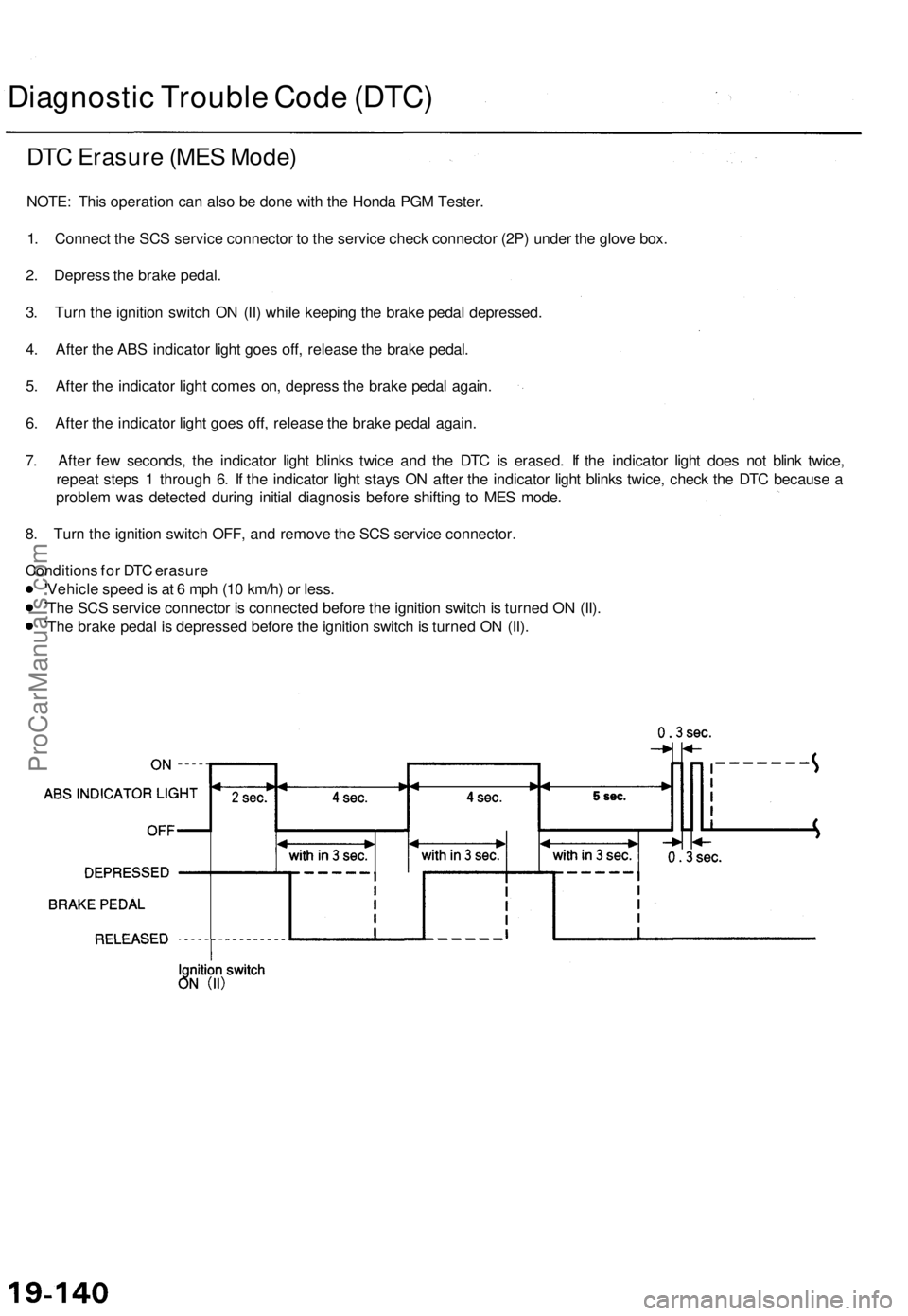
1. Connect the SCS service connector to the service check connector (2P) under the glove box.
2. Depress the brake pedal.
3. Turn the ignition switch ON (II) while keeping the brake pedal depressed.
4. After the ABS indicator light goes off, release the brake pedal.
5. After the indicator light comes on, depress the brake pedal again.
6. After the indicator light goes off, release the brake pedal again.
7. After few seconds, the indicator light blinks twice and the DTC is erased. If the indicator light does not blink twice,
repeat steps 1 through 6. If the indicator light stays ON after the indicator light blinks twice, check the DTC because a
problem was detected during initial diagnosis before shifting to MES mode.
8. Turn the ignition switch OFF, and remove the SCS service connector.
Conditions for DTC erasure
Vehicle speed is at 6 mph (10 km/h) or less.
The SCS service connector is connected before the ignition switch is turned ON (II).
The brake pedal is depressed before the ignition switch is turned ON (II).ProCarManuals.com
Page 1335 of 1771
Modulator Unit
Removal/Installation
CAUTION:
Do not spill brake fluid on the vehicle; it may damage the paint; if brake fluid does contact the paint, wash it off
immediately with water.
Take care not to damage or deform the brake lines during removal and installation.
To prevent the brake fluid from flowing, plug and cover the hose ends and joints with a shop towel or equivalent
material.
NOTE: Tighten the flare nuts to 15 N-m (1.5 kgf-m, 11 Ibf-ft).
Removal
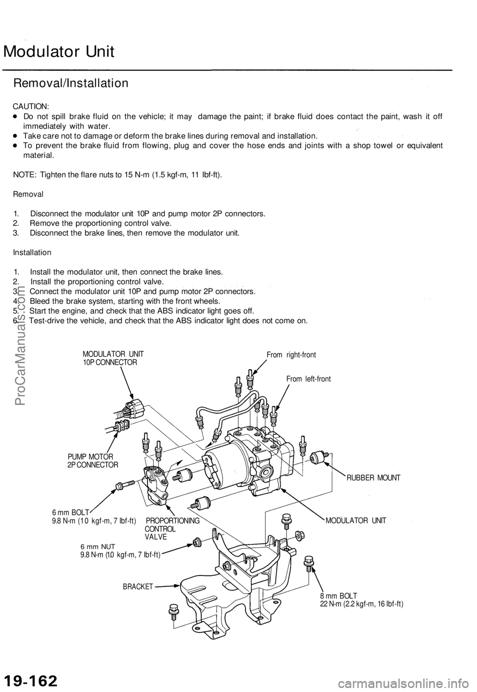
1. Disconnect the modulator unit 10P and pump motor 2P connectors.
2. Remove the proportioning control valve.
3. Disconnect the brake lines, then remove the modulator unit.
Installation
1. Install the modulator unit, then connect the brake lines.
2. Install the proportioning control valve.
3. Connect the modulator unit 10P and pump motor 2P connectors.
4. Bleed the brake system, starting with the front wheels.
5. Start the engine, and check that the ABS indicator light goes off.
6. Test-drive the vehicle, and check that the ABS indicator light does not come on.
MODULATOR UNIT
10P CONNECTOR
From right-front
From left-front
PUMP MOTOR
2P CONNECTOR
6 mm BOLT
9.8 N-m (1 .0 kgf-m, 7 Ibf-ft) PROPORTIONING
CONTROL
VALVE
6 mm NUT
9.8 N-m (1.0 kgf-m, 7 Ibf-ft)
BRACKET
RUBBER MOUNT
MODULATOR UNIT
8 mm BOLT
22 N-m (2.2 kgf-m, 16 Ibf-ft)ProCarManuals.com