Page 1605 of 1771
Brake System Indicator
Parking Brake Switch Test
1. Remove the center console, and disconnect the con-
nector from the switch.
2. Check for continuity between the terminal and body
ground in each switch position according to the table.
BRAKE LEVER
BODY
GROUND
POSITIVE
TERMINAL
NOTE (Canada): If the parking brake switch is OK,
but the brake system indicator does not function,
perform the input test for the daytime running
lights control unit.
Brake Fluid Level Switch Test
1. Remove the reservoir cap. Check that the float
moves up and down freely; if it doesn't, replace the
reservoir cap assembly.
2. Check for continuity between the terminals in each
switch position according to the table.
RESERVOIR CAP
FLOAT
Switch contacts closed
when float drops.
Switch contacts open at
proper fluid level.
UP POSITION
MAGNET
DOWN POSITION
DOWN
UPProCarManuals.com
Page 1617 of 1771

Safety Indicator
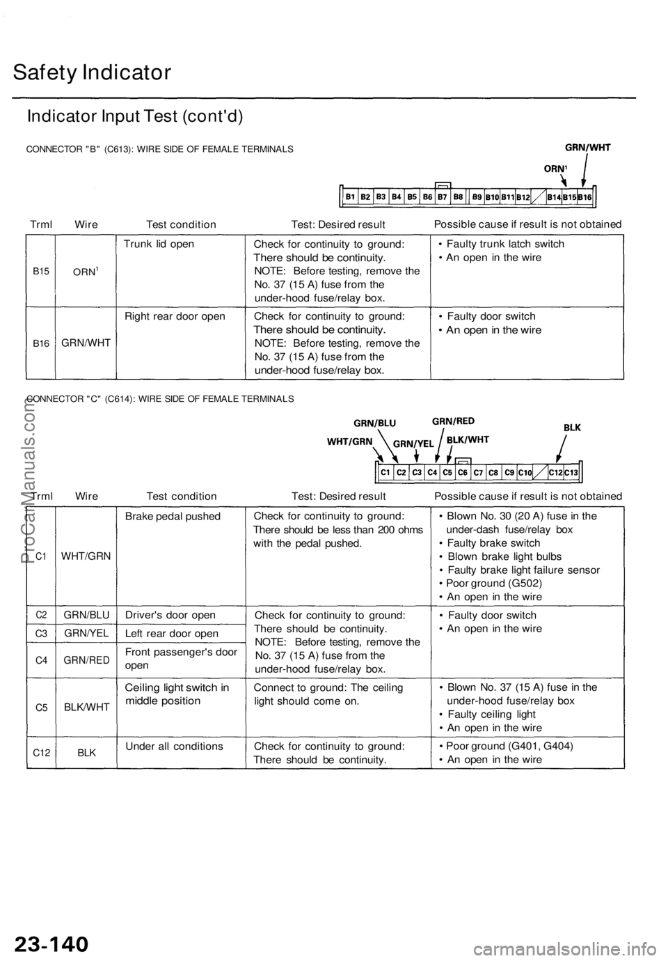
Indicator Input Test (cont'd)
CONNECTOR "B" (C613): WIRE SIDE OF FEMALE TERMINALS
Trml Wire
Test condition
Test: Desired result
Possible cause if result is not obtained
B15
B16
ORN1
GRN/WHT
Trunk lid open
Right rear door open
Check for continuity to ground:
There should be continuity.
NOTE: Before testing, remove the
No. 37 (15 A) fuse from the
under-hood fuse/relay box.
Check for continuity to ground:
There should be continuity.
NOTE: Before testing, remove the
No. 37 (15 A) fuse from the
under-hood fuse/relay box.
• Faulty trunk latch switch
• An open in the wire
• Faulty door switch
• An open in the wire
CONNECTOR "C" (C614): WIRE SIDE OF FEMALE TERMINALS
Trml Wire
Test condition
Test: Desired result
Possible cause if result is not obtained
C1
C2
C3
C4
C5
C12
WHT/GRN
GRN/BLU
GRN/YEL
GRN/RED
BLK/WHT
BLK
Brake pedal pushed
Driver's door open
Left rear door open
Front passenger's door
open
Ceiling light switch in
middle position
Under all conditions
Check for continuity to ground:
There should be less than 200 ohms
with the pedal pushed.
Check for continuity to ground:
There should be continuity.
NOTE: Before testing, remove the
No. 37 (15 A) fuse from the
under-hood fuse/relay box.
Connect to ground: The ceiling
light should come on.
Check for continuity to ground:
There should be continuity.
• Blown No. 30 (20 A) fuse in the
under-dash fuse/relay box
• Faulty brake switch
• Blown brake light bulbs
• Faulty brake light failure sensor
• Poor ground (G502)
• An open in the wire
• Faulty door switch
• An open in the wire
• Blown No. 37 (15 A) fuse in the
under-hood fuse/relay box
• Faulty ceiling light
• An open in the wire
• Poor ground (G401, G404)
• An open in the wireProCarManuals.com
Page 1618 of 1771

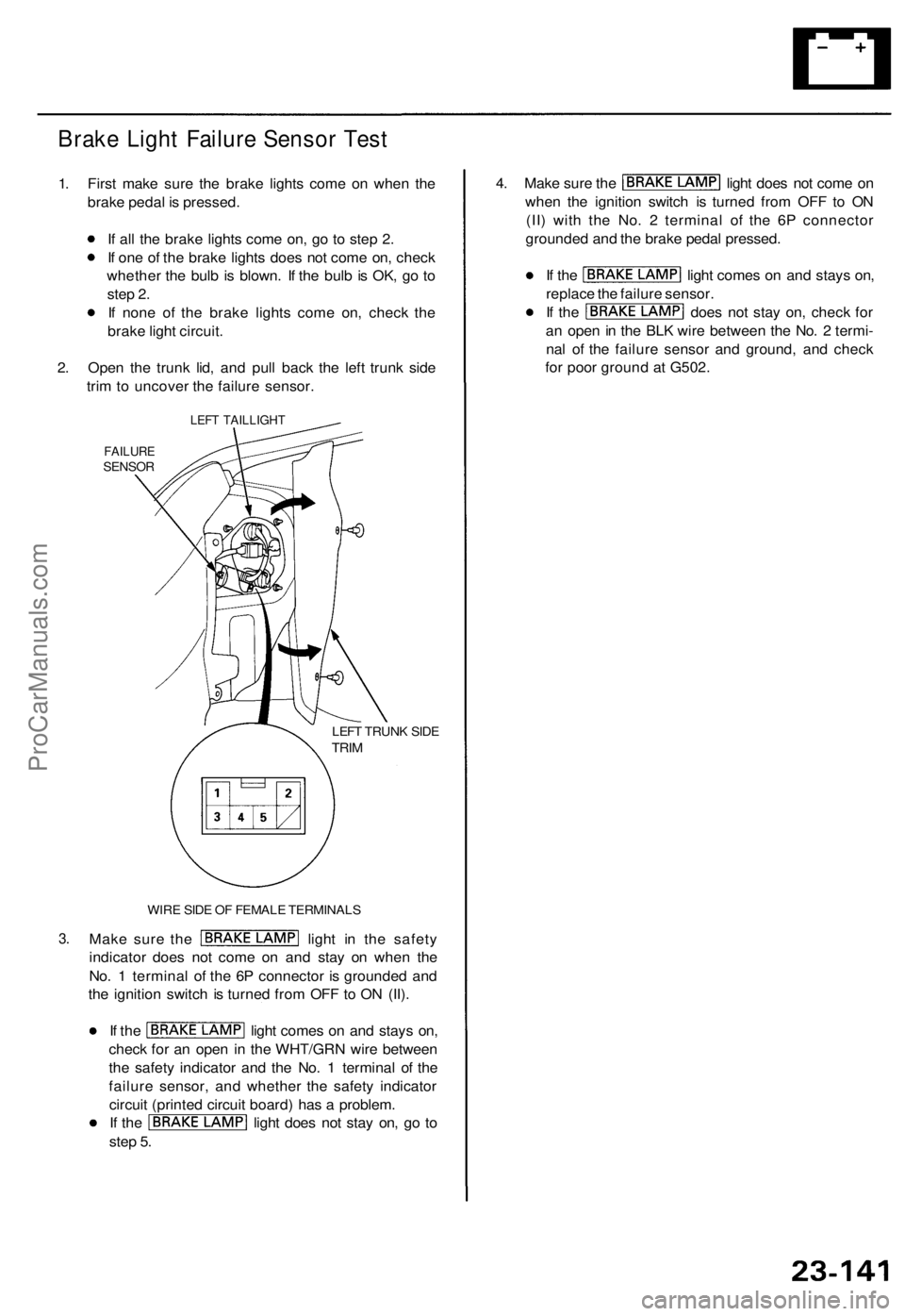
Brake Ligh t Failur e Senso r Tes t
1. Firs t mak e sur e th e brak e light s com e o n whe n th e
brak e peda l i s pressed .
I f al l th e brak e light s com e on , g o t o ste p 2 .
I f on e o f th e brak e light s doe s no t com e on , chec k
whethe r th e bul b i s blown . I f th e bul b is OK , g o t o
ste p 2 .
I f non e o f th e brak e light s com e on , chec k th e
brak e ligh t circui t.
2 . Ope n th e trun k lid , an d pul l bac k th e lef t trun k sid e
tri m to uncove r th e failur e sensor .
3.
LEF T TAILLIGH T
FAILURESENSOR
LEFT TRUN K SID ETRIM
WIR E SID E O F FEMAL E TERMINAL S
Make sur e th e ligh t i n th e safet y
indicato r doe s no t com e o n an d sta y o n whe n th e
No . 1 termina l o f th e 6 P connecto r i s grounde d an d
th e ignitio n switc h is turne d fro m OF F to O N (II) .
If th e ligh t come s o n an d stay s on ,
chec k fo r a n ope n i n th e WHT/GR N wir e betwee n
th e safet y indicato r an d th e No . 1 termina l o f th e
failur e sensor , an d whethe r th e safet y indicato r
circui t (printe d circui t board ) ha s a problem .
If th e ligh t doe s no t sta y on , g o t o
ste p 5 .
4. Mak e sur e th e ligh t doe s no t com e o n
whe n th e ignitio n switc h i s turne d fro m OF F t o O N
(II ) wit h th e No . 2 termina l of the 6 P connecto r
grounde d an d th e brak e peda l pressed .
If th e ligh t come s o n an d stay s on ,
replac e th e failur e sensor .
If th e doe s no t sta y on , chec k fo r
a n ope n in th e BL K wir e betwee n th e No . 2 termi -
na l o f th e failur e senso r an d ground , an d chec k
fo r poo r groun d a t G502 .
ProCarManuals.com
Page 1627 of 1771
Entry Light Timer System
Trml Wire Test condition
Test: Desired result
Possible cause if result is not obtained
Lights-on Reminder System:
Trml Wire Test condition
Test: Desired result
Possible cause if result is not obtainedProCarManuals.com
Page 1630 of 1771
Lighting Syste m
Componen t Locatio n Inde x
UNDER-HOO D
FUSE/RELA Y BO XHEADLIGH T RELA YTest, pag e 23-6 3
FO G LIGHT S
Bul b Replacement , pag e 23-17 0
Adjustment , pag e 23-16 8
HEADLIGHT S
Replacement , pag e 23-16 7
Adjustment , pag e 23-16 8
Bul b Replacement , pag e 23-16 7
FRONT PARKIN G LIGHT S
Bul b Replacement ,
pag e 23-16 6
FRON T SID E MARKE R LIGH T
Replacement , pag e 23-17 1
HIGH MOUN T BRAK E LIGH T
Replacement , pag e 23-18 4
LICENS E PLAT E LIGHT S
Replacement , pag e 23-17 3
TAILLIGH TBulb Replacement , pag e 23-17 2
Replacement , pag e 23-17 2
DIMME
R RELA Y
Test , pag e 23-6 3
FRON T TUR N SIGNA L LIGH T
Replacement , pag e 23-17 1
NOTE : Refe r t o page 23-100 a of th e '96-9 8 Acura
3.2TL Servic e Manual supplement for the differences
on this page for the 3.2TL.
ProCarManuals.com
Page 1631 of 1771
FOG LIGH T RELA YTest, pag e 23-6 2
DR L INDICATO R LIGH T (Canada )
LOW BEA M CU T RELA Y
(Canada )Test, pag e 23-6 2
FO G LIGH T
SWITC H
Replacement , pag e 23-26 9
Test , pag e 23-17 0
COMBINATIO N LIGH T SWITC H
Test , pag e 23-16 2
Replacement , pag e 23-16 6
DAYTIM E RUNNIN G LIGHT S
CONTRO L UNI T (Canada )
Inpu t Test , pag e 23-16 4
A/
T GEA R POSITIO N
INDICATO R PANE L LIGH T
Replacement , pag e 23-17 3
HIG
H BEA M INDICATO R LIGH T
Bul b Locations , pag e 23-11 5
ProCarManuals.com
Page 1632 of 1771

Lighting Syste m
Combinatio n Ligh t Switc h Tes t
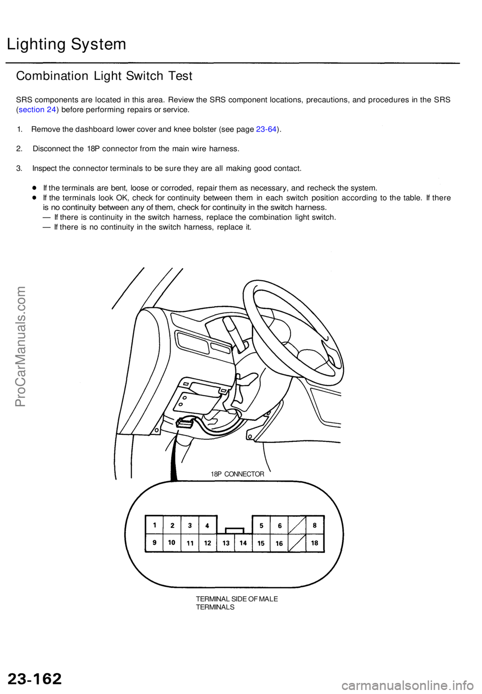
SRS component s ar e locate d in thi s area . Revie w th e SR S componen t locations , precautions , an d procedure s i n th e SR S
( sectio n 24 ) befor e performin g repair s o r service .
1 . Remov e th e dashboar d lowe r cove r an d kne e bolste r (se e pag e 23-64 ).
2 . Disconnec t th e 18 P connecto r fro m th e mai n wir e harness .
3 . Inspec t th e connecto r terminal s t o b e sur e the y ar e al l makin g goo d contact .
I f th e terminal s ar e bent , loos e o r corroded , repai r the m a s necessary , an d rechec k th e system .
I f th e terminal s loo k OK , chec k fo r continuit y betwee n the m in eac h switc h positio n accordin g t o th e table . I f ther e
is n o continuit y betwee n an y o f them , chec k fo r continuit y in th e switc h harness .
— If ther e i s continuit y i n th e switc h harness , replac e th e combinatio n ligh t switch .
— If ther e i s n o continuit y i n th e switc h harness , replac e it .
18 P CONNECTO R
TERMINAL SID E O F MAL ETERMINAL S
ProCarManuals.com
Page 1633 of 1771
Headlight/Dimmer/Passing Switc h
ProCarManuals.com