Page 47 of 1771

25. Loosen the mounting bolt, lock bolt and adjusting
rod, then remove the alternator belt.
ADJUSTING
ROD
LOCK BOLT
8 x
1.25
mm
22 N-m (2.2 kgf-m,
16 Ibf-ft)
ALTERNATOR
BELT
MOUNTING BOLT
10 x
1.25
mm
44 N-m (4.5 kgf-m,
33 Ibf-ft)
26. Loosen the idler pulley center nut and adjusting bolt,
then remove the air conditioning (A/C) compressor
belt.
IDLER PULLEY
CENTER NUT
10 x
1.25
mm
44 N-m (4.5 kgf-m,
33 Ibf-ft)
ADJUSTING
BOLT
A/C COMPRESSOR
BELT
27. Disconnect the power steering pressure (PSP)
switch connector.
28. Remove the adjusting bolt, locknut and mounting
bolt, then remove the P/S pump belt and pump.
Do not disconnect the P/S hose.
ADJUSTING
BOLT
P/S PUMP
LOCKNUT
8 x
1.25
mm
22 N-m (2.2 kgf-m,
16 Ibf-ft)
PSP SWITCH
CONNECTOR
29.
P/S PUMP
BELT
MOUNTING BOLT
10 x
1.25
mm
44 N-m (4.5 kgf-m, 33 Ibf-ft)
Pull the carpet back to expose the secondary heated
oxygen sensor (Secondary HO2S) connector, then
disconnect the secondary HO2S connector.
SECONDARY
HO2S CONNECTORProCarManuals.com
Page 61 of 1771
Timing Bel t
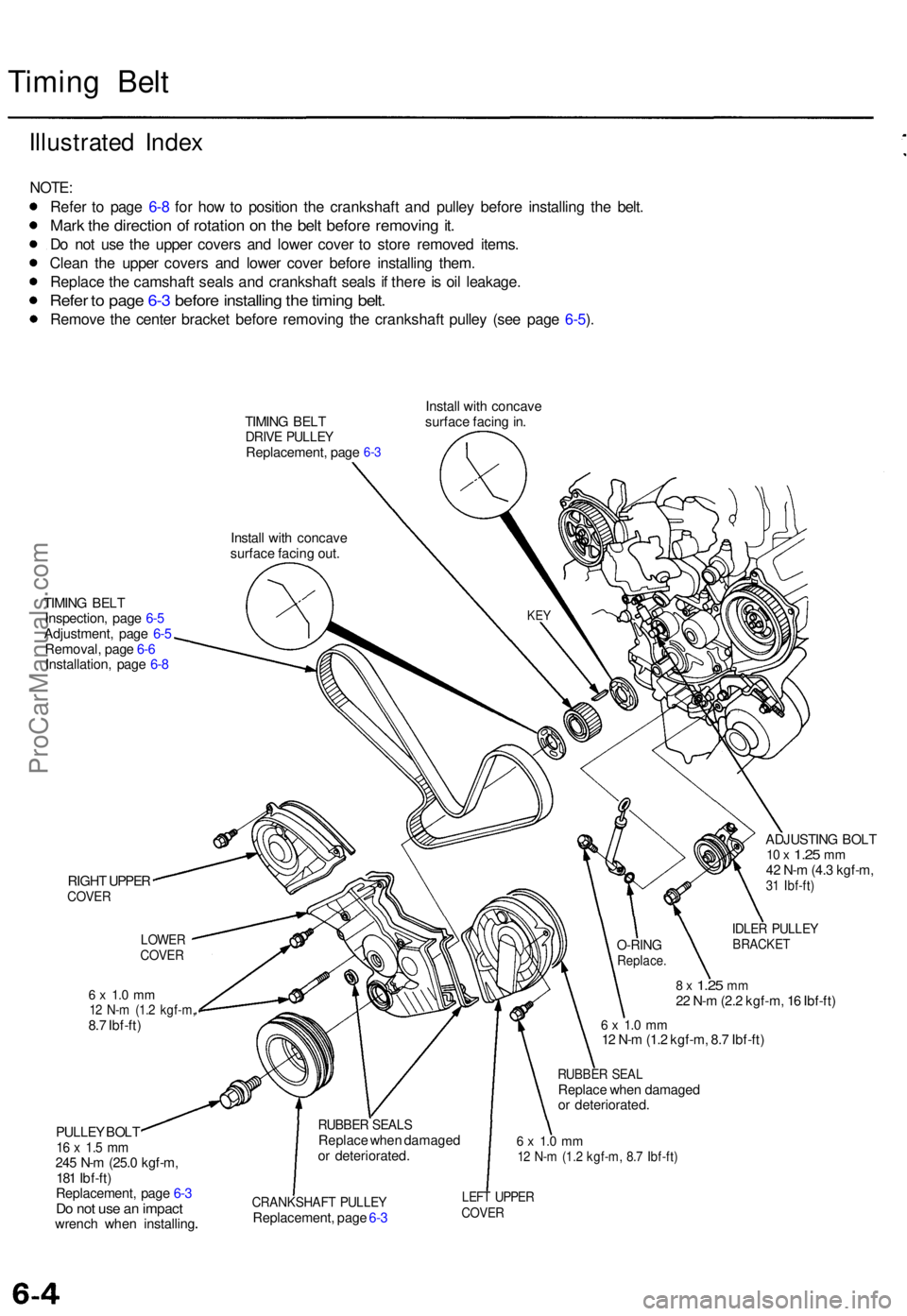
Illustrate d Inde x
NOTE :
Refe r t o pag e 6- 8 fo r ho w to positio n th e crankshaft and pulle y befor e installin g th e belt .
Mark th e directio n o f rotatio n o n th e bel t befor e removin g it .
Do no t us e th e uppe r cover s an d lowe r cove r t o stor e remove d items .
Clea n th e uppe r cover s an d lowe r cove r befor e installin g them .
Replac e th e camshaf t seal s an d crankshaf t seal s i f ther e is oi l leakage .
Refer t o pag e 6- 3 befor e installin g th e timin g belt .
Remov e th e cente r bracke t befor e removin g th e crankshaf t pulle y (se e pag e 6-5 ).
TIMIN G BEL TDRIV E PULLE YReplacement , pag e
Instal l wit h concav e
surfac e facin g out . Instal
l wit h concav e
surfac e facin g in .6-3
TIMIN G BEL T
Inspection , pag e 6- 5
Adjustment , pag e 6-5
Removal , pag e 6- 6
Installation , pag e 6- 8
RIGH T UPPE R
COVE R
6 x 1. 0 m m12 N- m (1. 2 kgf-m ,8.7 Ibf-ft )
PULLE Y BOL T
16 x 1. 5 m m245 N- m (25. 0 kgf-m ,
18 1 Ibf-ft )
Replacement , pag e 6- 3
Do no t us e a n impac twrench whe n installin g ADJUSTIN
G BOL T
10 x 1.2 5 mm42 N- m (4. 3 kgf-m ,31 Ibf-ft )
IDLER PULLE YBRACKE T
8 x 1.2 5 mm22 N- m (2. 2 kgf-m , 1 6 Ibf-ft )
6 x 1. 0 m m12 N- m (1. 2 kgf-m , 8. 7 Ibf-ft )
RUBBE R SEA LReplac e whe n damage d
o r deteriorated .
6 x 1. 0 m m12 N- m (1. 2 kgf-m , 8. 7 Ibf-ft )
CRANKSHAF T PULLE YReplacement , pag e 6- 3
LEF T UPPE RCOVER
RUBBE R SEAL SReplac e whe n damage d
o r deteriorated .
O-RINGReplace .
LOWERCOVER
KEY
ProCarManuals.com
Page 62 of 1771
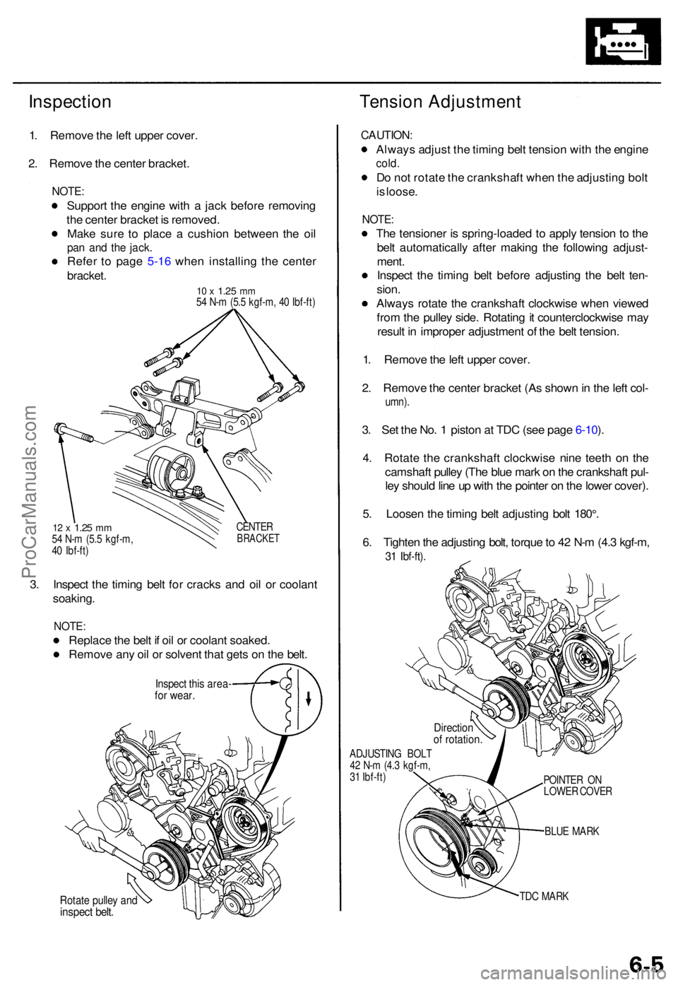
InspectionTension Adjustmen t
1. Remov e th e lef t uppe r cover .
2 . Remov e th e cente r bracket .
NOTE:
Suppor t th e engin e wit h a jac k befor e removin g
th e cente r bracke t i s removed .
Mak e sur e t o plac e a cushio n betwee n th e oi l
pan an d th e jack .
Refe r t o pag e 5-1 6 whe n installin g th e cente r
bracket .
10 x 1.2 5 mm54 N- m (5. 5 kgf-m , 4 0 Ibf-ft )
12 x 1.2 5 mm54 N- m (5. 5 kgf-m ,
4 0 Ibf-ft ) CENTE
RBRACKE T
3. Inspec t th e timin g bel t fo r crack s an d oi l o r coolan t
soaking .
NOTE:
Replac e th e bel t i f oi l o r coolan t soaked .
Remov e an y oi l o r solven t tha t get s o n th e belt .
Inspec t thi s area -for wear .
Rotate pulle y an dinspec t belt .
CAUTION :
Always adjus t th e timin g bel t tensio n wit h th e engin e
cold.
Do no t rotat e th e crankshaf t whe n th e adjustin g bol t
i s loose .
NOTE :
The tensione r i s spring-loade d t o appl y tensio n t o th e
bel t automaticall y afte r makin g th e followin g adjust -
ment .
Inspec t th e timin g bel t befor e adjustin g th e bel t ten -
sion .
Alway s rotat e th e crankshaf t clockwis e whe n viewe d
fro m th e pulle y side . Rotatin g it counterclockwis e ma y
resul t i n imprope r adjustmen t o f th e bel t tension .
1 . Remov e th e lef t uppe r cover .
2 . Remov e th e cente r bracke t (A s show n in th e lef t col -
umn) .
3. Se t th e No . 1 pisto n a t TD C (se e pag e 6-10 ).
4 . Rotat e th e crankshaf t clockwis e nin e teet h o n th e
camshaf t pulle y (Th e blu e mar k o n th e crankshaf t pul -
le y shoul d lin e u p wit h th e pointe r o n th e lowe r cover) .
5 . Loose n th e timin g bel t adjustin g bol t 180° .
6 . Tighte n th e adjustin g bolt , torqu e to 4 2 N- m (4. 3 kgf-m ,
31 Ibf-ft) .
ADJUSTIN G BOL T
4 2 N- m (4. 3 kgf-m ,
3 1 Ibf-ft )
BLUE MAR K
TD C MAR K
POINTE
R O N
LOWE R COVE R
Directio nof rotation .
ProCarManuals.com
Page 63 of 1771
Timing Bel t
Remova l
NOTE:
Replac e th e timin g bel t a t 105,00 0 mile s (168,00 0 km )
accordin g t o th e maintenanc e schedul e (norma l con -
ditions/sever e conditions) .
I f th e vehicl e is regularl y drive n i n on e o r mor e o f th e
followin g conditions , replac e th e timin g bel t a t 60,00 0
mile s (U.S.A. ) 100,00 0 k m (Canada) .
I n ver y hig h temperature s (ove r 110°F , 43°C )
I n ver y lo w temperature s (unde r -20°F , -29°C )
Tur n th e crankshaf t pulle y s o th e No . 1 pisto n i s a t
to p dea d cente r (TDC ) befor e removin g th e bel t (se e
pag e 6-8 ).
Inspec t th e wate r pum p befor e installin g th e timin g
bel t (se e pag e 10-10 ).
1 . Mak e sur e yo u hav e th e anti-thef t cod e fo r th e radio ,
the n writ e dow n th e frequencie s fo r th e radio' s prese t
buttons .
2. Disconnec t th e negativ e termina l fro m th e battery .
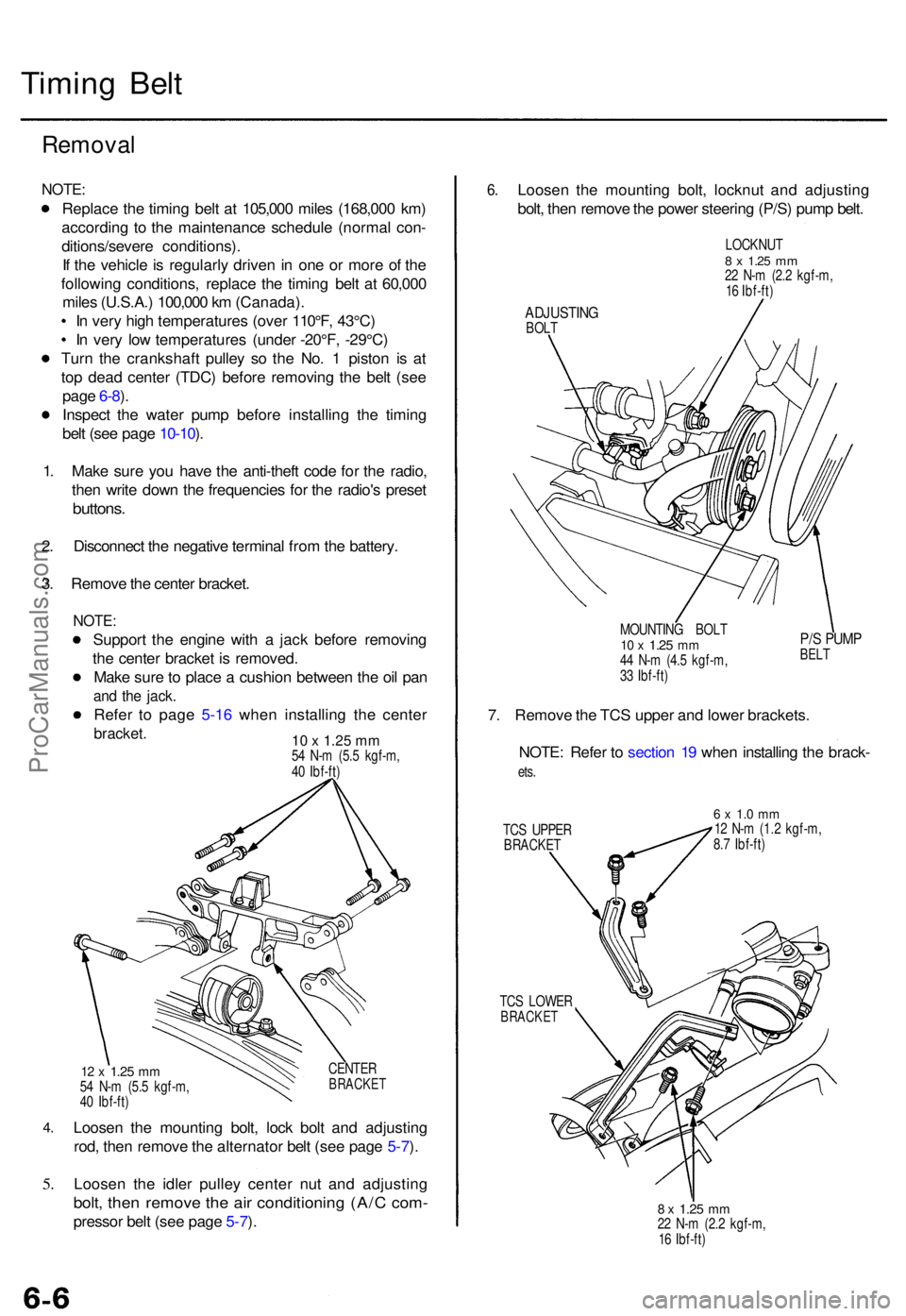
3 . Remov e th e cente r bracket .
NOTE:
Suppor t th e engin e wit h a jac k befor e removin g
th e cente r bracke t i s removed .
Mak e sur e to plac e a cushio n betwee n th e oi l pa n
and th e jack .
Refer t o pag e 5-1 6 whe n installin g th e cente r
bracket. 10 x 1.25 mm54 N- m (5. 5 kgf-m ,
4 0 Ibf-ft )
4.
5.
CENTE RBRACKE T12 x 1.2 5 mm54 N- m (5. 5 kgf-m ,
4 0 Ibf-ft )
Loose n th e mountin g bolt , loc k bol t an d adjustin g
rod , the n remov e th e alternato r bel t (se e pag e 5-7 ).
Loose n th e idle r pulle y cente r nu t an d adjustin g
bolt, the n remov e th e ai r conditionin g (A/ C com -
presso r bel t (se e pag e 5-7 ).
6 .Loose n th e mountin g bolt , locknu t an d adjustin g
bolt , the n remov e th e powe r steerin g (P/S ) pum p belt .
LOCKNU T8 x 1.2 5 mm22 N- m (2. 2 kgf-m ,
1 6 Ibf-ft )
ADJUSTIN GBOLT
MOUNTING BOL T
10 x 1.2 5 mm44 N- m (4. 5 kgf-m ,
3 3 Ibf-ft )
P/S PUM PBELT
7. Remov e th e TC S uppe r an d lowe r brackets .
NOTE : Refe r t o sectio n 1 9 whe n installin g th e brack -
ets.
TC S UPPE RBRACKE T
6 x 1. 0 m m12 N- m (1. 2 kgf-m ,
8. 7 Ibf-ft )
TC S LOWE R
BRACKE T
8 x 1.2 5 mm22 N- m (2. 2 kgf-m ,
1 6 Ibf-ft )
ProCarManuals.com
Page 65 of 1771
Timing Belt
Removal (cont'd)
13. Loosen the adjusting bolt 180°. Push the tensioner to
remove tension from the timing belt, then retighten
the adjusting bolt.
ADJUSTING BOLT
10 x
1.25
mm
42 N-m (4.3 kgf-m, 31 Ibf-ft)
14. Remove the timing belt.ProCarManuals.com
Page 67 of 1771
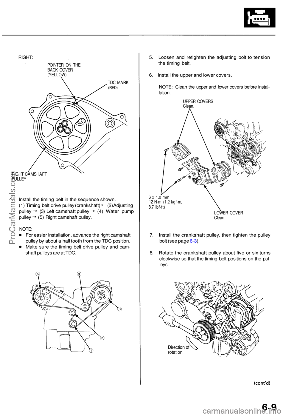
RIGHT:
POINTE R O N TH E
BAC K COVE R
(YELLOW )
TDC MAR K(RED)
RIGHT CAMSHAF TPULLEY
4. Instal l th e timin g bel t i n th e sequenc e shown .
(1) Timin g bel t driv e pulle y (crankshaft ) (2 ) Adjustin g
pulley (3 ) Lef t camshaf t pulle y (4) Wate r pum p
pulley (5) Right camshaf t pulley .
NOTE:
For easie r installation , advanc e th e righ t camshaf t
pulle y b y abou t a hal f toot h fro m th e TD C position .
Mak e sur e th e timin g bel t driv e pulle y an d cam -
shaf t pulley s ar e a t TDC . 5
. Loose n an d retighte n th e adjustin g bol t t o tensio n
th e timin g belt .
6 . Instal l th e uppe r an d lowe r covers .
NOTE: Clea n th e uppe r an d lowe r cover s befor e instal -
lation.
UPPE R COVER S
Clean .
6 x 1. 0 m m12 N- m (1. 2 kgf- m
8. 7 Ibf-ft )
LOWER COVE R
Clean .
7. Instal l th e crankshaf t pulley , the n tighte n th e pulle y
bol t (se e pag e 6-3 ).
8 . Rotat e th e crankshaf t pulle y abou t fiv e o r si x turn s
clockwis e s o tha t th e timin g bel t position s o n th e pul -
leys .
Directio n o frotation .
ProCarManuals.com
Page 68 of 1771
Timing Bel t
Installatio n (cont'd )
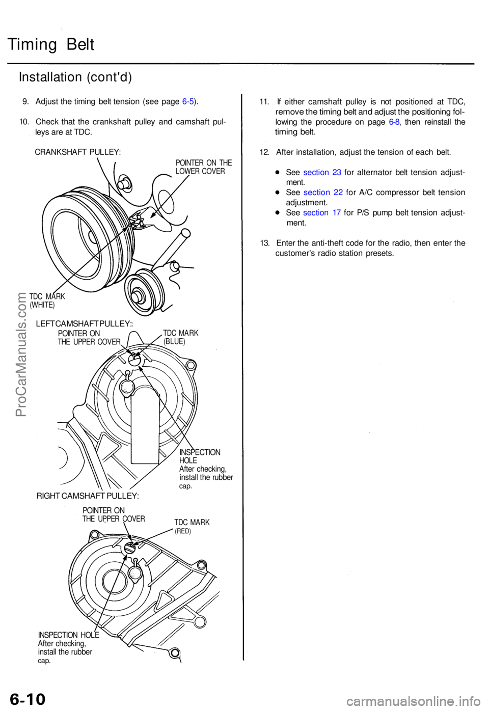
9. Adjus t th e timin g bel t tensio n (se e pag e 6-5 ).
10 . Chec k tha t th e crankshaf t pulle y an d camshaf t pul -
ley s ar e a t TDC .
CRANKSHAF T PULLEY :
TDC MAR K
(WHITE )
LEFT CAMSHAF T PULLEY :
POINTER O NTH E UPPE R COVE R
RIGHT CAMSHAF T PULLEY :
POINTER O NTH E UPPE R COVE R POINTE
R O N TH E
LOWE R COVE R
TD C MAR K
(BLUE )
INSPECTIO NHOLEAfter checking ,install th e rubbe rcap.
TDC MAR K(RED)
INSPECTIO N HOL EAfter checking ,install th e rubbe rcap.
11. I f eithe r camshaf t pulle y i s no t positione d a t TDC ,
remov e th e timin g bel t an d adjus t th e positionin g fol -
lowin g th e procedur e o n pag e 6-8 , the n reinstal l th e
timin g belt .
12. Afte r installation , adjus t th e tensio n o f eac h belt .
Se e sectio n 2 3 fo r alternato r bel t tensio n adjust -
ment .
Se e sectio n 2 2 fo r A/ C compresso r bel t tensio n
adjustment .
Se e sectio n 1 7 fo r P/ S pum p bel t tensio n adjust -
ment .
13 . Ente r th e anti-theft code fo r th e radio , the n ente r th e
customer' s radi o statio n presets .
ProCarManuals.com
Page 69 of 1771
CKP/CYP Senso r
Replacemen t
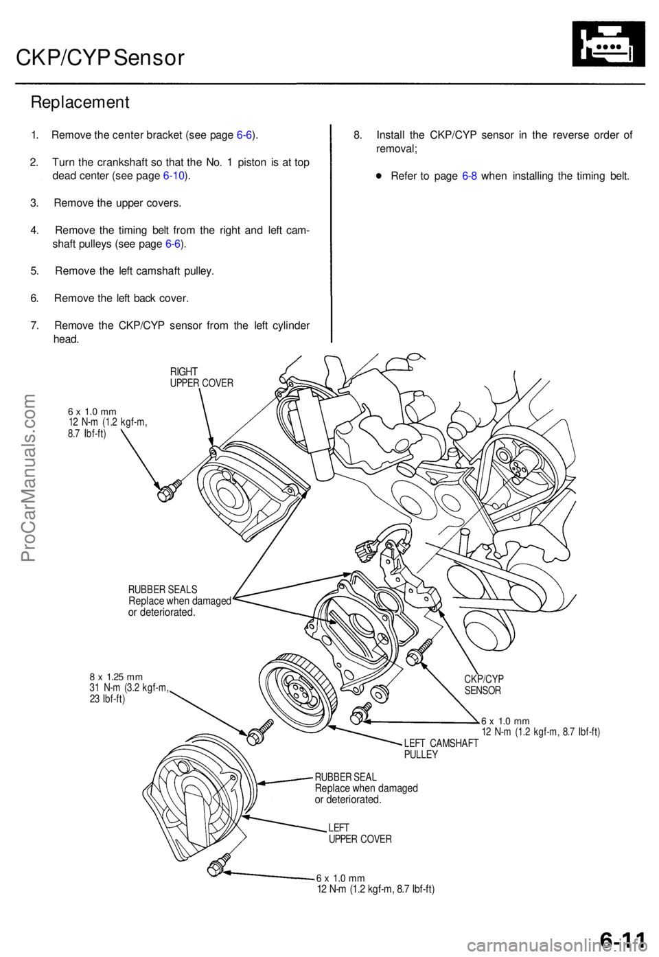
1. Remov e th e cente r bracke t (se e pag e 6-6 ).
2 . Tur n th e crankshaf t s o tha t th e No . 1 pisto n i s a t to p
dea d cente r (se e pag e 6-10 ).
3 . Remov e th e uppe r covers .
4 . Remov e th e timin g bel t fro m th e righ t an d lef t cam -
shaf t pulley s (se e pag e 6-6 ).
5 . Remov e th e lef t camshaf t pulley .
6 . Remov e th e lef t bac k cover .
7 . Remov e th e CKP/CY P senso r fro m th e lef t cylinde r
head .
RIGH TUPPE R COVE R
6 x 1. 0 m m12 N- m (1. 2 kgf-m ,
8. 7 Ibf-ft )
8. Instal l th e CKP/CY P senso r i n th e revers e orde r o f
removal ;
Refe r t o pag e 6- 8 whe n installin g th e timin g belt .
RUBBE R SEAL SReplac e whe n damage dor deteriorated .
8 x 1.2 5 mm31 N- m (3. 2 kgf-m ,
2 3 Ibf-ft )
6 x 1. 0 m m12 N- m (1. 2 kgf-m , 8. 7 Ibf-ft )
LEF T CAMSHAF T
PULLE Y
RUBBE R SEA L
Replac e whe n damage dor deteriorated .
LEFTUPPE R COVE R
6 x 1. 0 m m12 N- m (1. 2 kgf-m , 8. 7 Ibf-ft )
CKP/CY P
SENSO R
ProCarManuals.com