Page 1536 of 1771

Troubleshooting
Tips and Precautions
Before Troubleshooting
Check applicable fuses in the appropriate fuse/relay
box.
Check the battery for damage, state of charge, and
clean and tight connections.
Check the alternator belt tension.
CAUTION:
Do not quick-charge a battery unless the battery
ground cable has been disconnected, otherwise you
will damage the alternator diodes.
Do not attempt to crank the engine with the battery
ground cable loosely connected or you will severely
damage the wiring.
Handling Connectors
Make sure the connectors are clean and have no loose
wire terminals.
Make sure multiple cavity connectors are packed with
grease (except waterproof connectors).
All connectors have push-down release type locks.
LOCKING TAB
Some connectors have a clip on their side used to
attach them to a mount bracket on the body or on
another component. This clip has a pull type lock.
Some mounted connectors cannot be disconnected
unless you first release the lock and remove the con-
nector from its mount bracket.
LOCKING
PAWL ON
OTHER
HALF OF
CONNECTOR
Pull to
disengage
BRACKET
Never try to disconnect connectors by pulling on
their wires; pull on the connector halves instead.
Always reinstall plastic covers.
Before connecting connectors, make sure the termi-
nals are in place and not bent.
BENT TERMINAL
Check for loose retainer and rubber seals.
RETAINER
RUBBER SEAL RETAINER
The backs of some connectors are packed with
grease. Add grease if necessary. If the grease is con-
taminated, replace it.
LOCKING TABProCarManuals.com
Page 1587 of 1771

Charging Syste m
Alternato r Bel t Inspectio n an d Adjustmen t
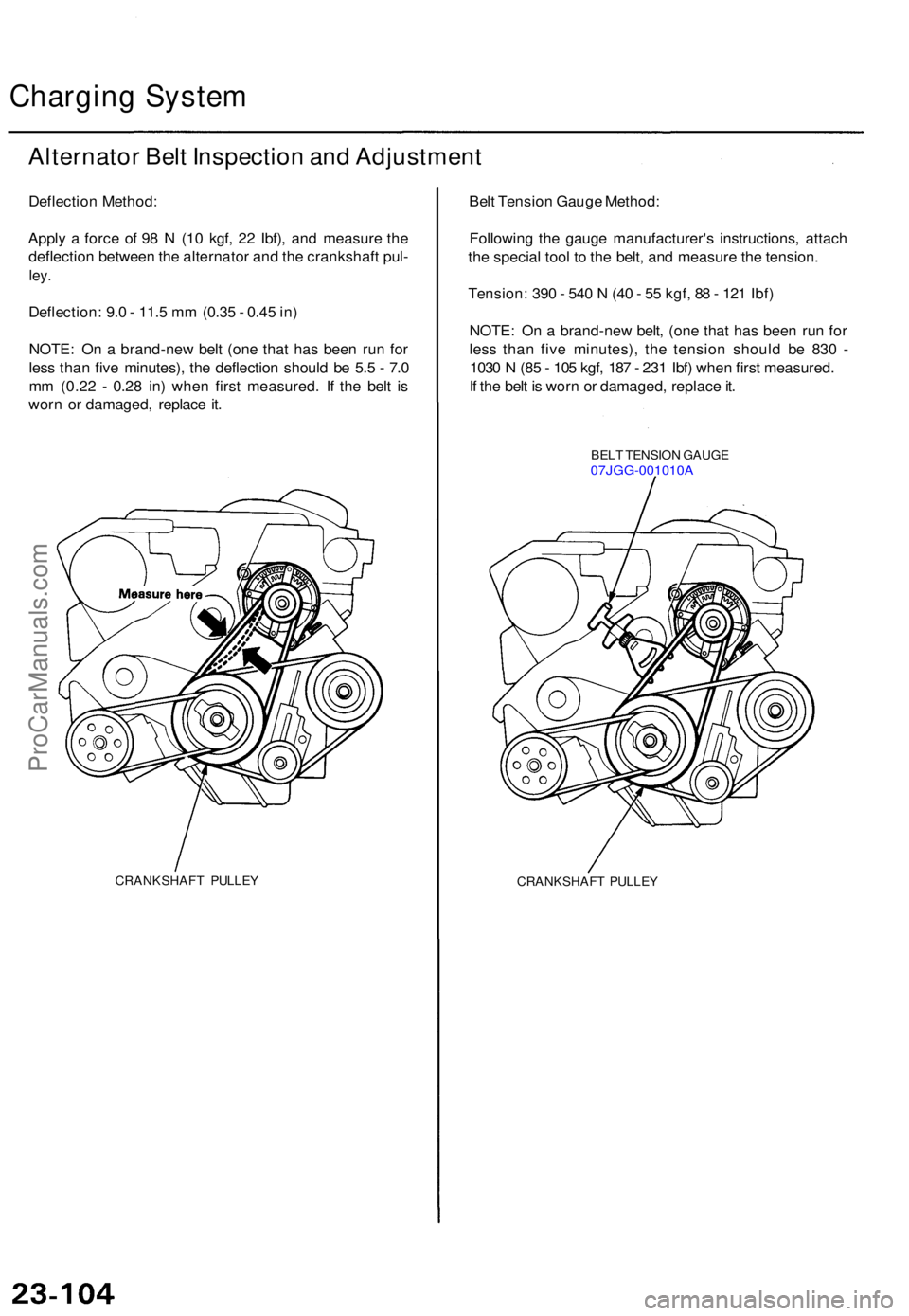
Deflection Method :
Appl y a forc e o f 9 8 N (1 0 kgf , 2 2 Ibf) , an d measur e th e
deflectio n betwee n th e alternato r an d th e crankshaf t pul -
ley.
Deflection : 9. 0 - 11. 5 m m (0.3 5 - 0.4 5 in )
NOTE : O n a brand-ne w bel t (on e tha t ha s bee n ru n fo r
les s tha n fiv e minutes) , th e deflectio n shoul d b e 5. 5 - 7. 0
m m (0.2 2 - 0.2 8 in ) whe n firs t measured . I f th e bel t i s
wor n o r damaged , replac e it .
CRANKSHAF T PULLE Y
Belt Tensio n Gaug e Method :
Followin g th e gaug e manufacturer' s instructions , attac h
th e specia l too l t o th e belt , an d measur e th e tension .
Tension : 39 0 - 54 0 N (4 0 - 5 5 kgf , 8 8 - 12 1 Ibf )
NOTE : O n a brand-ne w belt , (on e tha t ha s bee n ru n fo r
les s tha n fiv e minutes) , th e tensio n shoul d b e 83 0 -
103 0 N (8 5 - 10 5 kgf , 18 7 - 23 1 Ibf ) whe n firs t measured .
I f th e bel t i s wor n o r damaged , replac e it .
BEL T TENSIO N GAUG E07JGG-001010 A
CRANKSHAFT PULLE Y
ProCarManuals.com
Page 1588 of 1771
If adjustmen t i s necessary :
1 . Loose n th e throug h bol t an d th e adjustin g loc k bolt .
2 . Mov e th e alternato r b y turnin g th e adjustin g nu t t o
obtai n th e prope r bel t tension , the n retighte n th e
bolts .
THROUG H BOL T
4 4 N- m (4. 5 kgf-m , 3 3 Ibf-ft )
ADJUSTMEN T LOC K BOL T
2 2 N- m (2. 2 kgf-m ,
1 6 Ibf-ft )
To loose n bel t
ADJUSTIN G NU T8 N- m (0. 8 kgf-m , 6 Ibf-ft )
3. Rechec k th e deflectio n o r tensio n o f th e belt .
NOTE : Fo r th e powe r steerin g pum p bel t an d A/ C
compresso r bel t adjustments , refe r t o sectio n 1 7 an d
sectio n 22 .
ProCarManuals.com
Page 1595 of 1771
Bulb Locations
GAUGE LIGHTS
(1.4
W x 2)
HIGH BEAM INDICATOR LIGHT (1.4 W)
SEAT BELT REMINDER LIGHT (1.4 W)
RIGHT TURN SIGNAL INDICATOR LIGHT (1.4 W)
MALFUNCTION INDICATOR LAMP
(MIL) (1.4
W)
LOW FUEL
INDICATOR LIGHT (3 W)
BRAKE SYSTEM LIGHT (1.4 W)
LEFT TURN SIGNAL INDICATOR LIGHT (1.4 W)
SRS INDICATOR LIGHT (1.4 W)
(On the SRS printed circuit board)
CHARGING SYSTEM LIGHT (1.4 W)
LOW ENGINE OIL PRESSURE
INDICATOR LIGHT (1.4 W)
ABS INDICATOR LIGHT (1.4 W)
DRL INDICATOR
LIGHT (1.4 W) (Canada)
CRUISE LIGHT (2 W)
A/T GEAR POSITION INDICATOR LIGHTS (1.12 W x 7)
GAUGE LIGHTS
(3.4
W x 2)
SAFETY
INDICATOR
LIGHTS
(1.12
W x 6)
GAUGE LIGHTS
(3.4
W x 3)ProCarManuals.com
Page 1626 of 1771
Integrated Control Unit
Input Test (cont'd)
Seat Belt Reminder and Key-in Warning System:
WIRE SIDE OF FEMALE TERMINALS
*: '97 - 98 models
Trml Wire
Test condition
Test: Desired result
Possible cause if result is not obtained
Power Window Key-off Timer System:
Trml Wire
Test condition
Test: Desired result
Possible cause if result is not obtainedProCarManuals.com
Page 1739 of 1771

Description
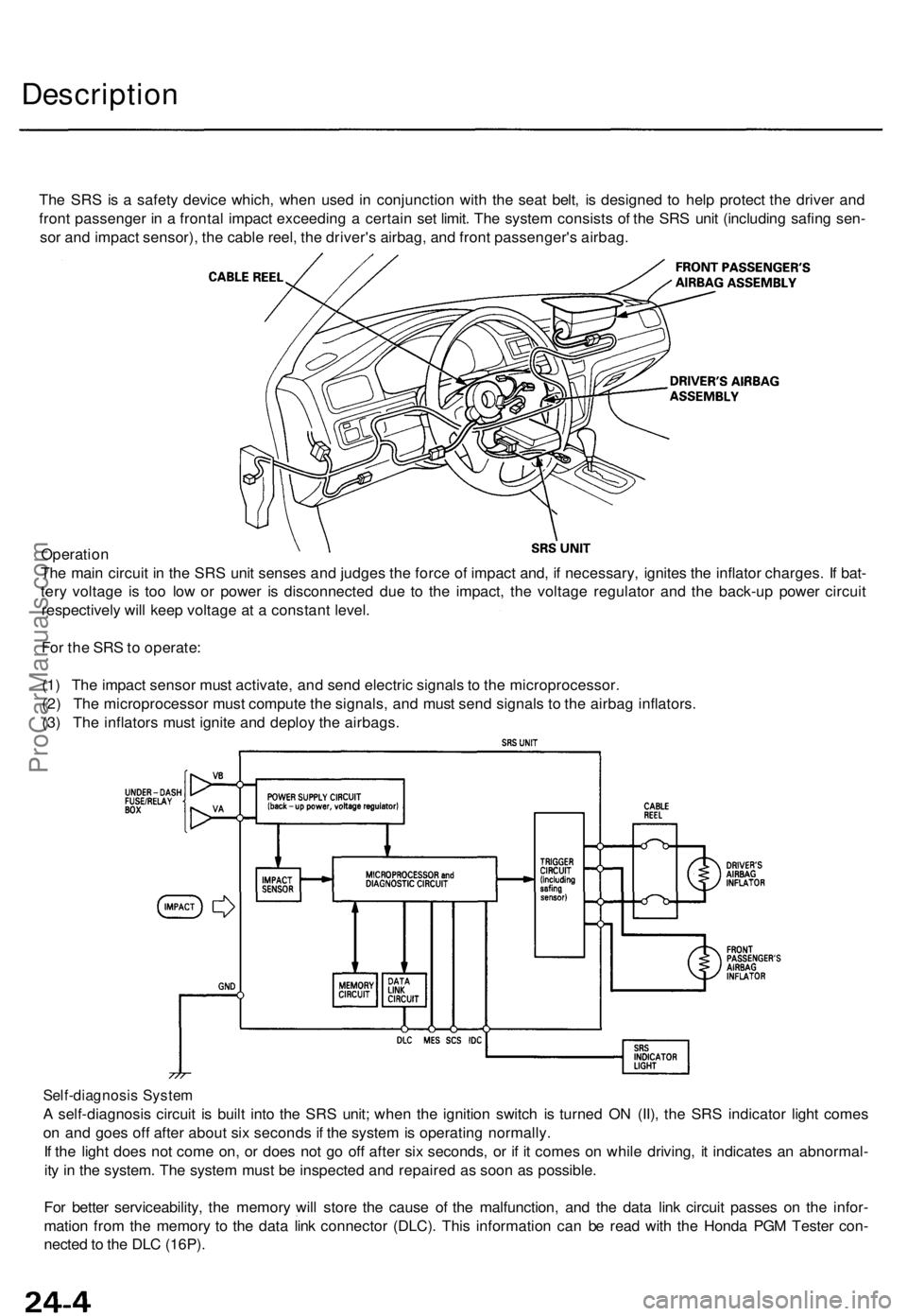
The SR S is a safet y devic e which , whe n use d i n conjunctio n wit h th e sea t belt , i s designe d t o hel p protec t th e drive r an d
fron t passenge r i n a fronta l impac t exceedin g a certai n se t limit . Th e syste m consist s o f th e SR S uni t (includin g safin g sen -
so r an d impac t sensor) , th e cabl e reel , th e driver' s airbag , an d fron t passenger' s airbag .
Operatio n
Th e mai n circui t i n th e SR S uni t sense s an d judge s th e forc e o f impac t and , i f necessary , ignite s th e inflato r charges . I f bat -
ter y voltag e i s to o lo w o r powe r i s disconnecte d du e t o th e impact , th e voltag e regulato r an d th e back-u p powe r circui t
respectivel y wil l kee p voltag e a t a constan t level .
Fo r th e SR S to operate :
(1 ) Th e impac t senso r mus t activate , an d sen d electri c signal s t o th e microprocessor .
(2 ) Th e microprocesso r mus t comput e th e signals , an d mus t sen d signal s t o th e airba g inflators .
(3 ) Th e inflator s mus t ignit e an d deplo y th e airbags .
Self-diagnosi s Syste m
A self-diagnosi s circui t i s buil t int o th e SR S unit ; whe n th e ignitio n switc h i s turne d O N (II) , th e SR S indicato r ligh t come s
o n an d goe s of f afte r abou t si x second s if th e syste m is operatin g normally .
I f th e ligh t doe s no t com e on , o r doe s no t g o of f afte r si x seconds , o r i f i t come s o n whil e driving , i t indicate s a n abnormal -
it y i n th e system . Th e syste m mus t b e inspecte d an d repaire d a s soo n a s possible .
Fo r bette r serviceability , th e memor y wil l stor e th e caus e o f th e malfunction , an d th e dat a lin k circui t passe s o n th e infor -
matio n fro m th e memor y t o th e dat a lin k connecto r (DLC) . Thi s informatio n ca n b e rea d wit h th e Hond a PG M Teste r con -
necte d to th e DL C (16P) .
ProCarManuals.com
Page 1771 of 1771

SUPPLEMENTAL RESTRAINT SYSTEMThe Acura TL SRS includes a driver's airbag located in the steering wheel hub and a passenger's airbag located in the dashboard above
the glove box. Information necessary to safely service the SRS is included in this Service Manual. Items marked with an asterisk (*) on
the contents page include, or are located near, SRS components. Servicing, disassembling or replacing these items will require special
precautions and tools, and should therefore be done by an authorized Honda dealer.
WARNING
�To avoid rendering the SRS inoperative, which could lead to personal injury or death in the event of a severe frontal
collision, all SRS service work must be performed by an authorized Honda dealer.
�Improper service procedures, including incorrect removal and installation of the SRS, could lead to personal injury
caused by unintentional activation of the front airbags, seat belt tensioners, and side airbags ('99-01 models).
�Do not bump the SRS unit. Otherwise, the system may fail in a collision, or the airbags may deploy when the ignition
switch in ON (II).
�All SRS electrical wiring harnesses are covered with yellow insulation. Related components are located in the steering
column, front console, dashboard, dashboard lower panel, in the dashboard above the glove box. Do not use electrical
test equipment on these circuits.
NOTE: The original radio has a coded theft protection circuit. Be sure to get the customer's code number before
± disconnecting the battery.
± removing the No. 39 (10A) fuse from the under±hood fuse/relay box.
± removing the radio.
After service, reconnect power to the radio and turn it on. When the word ºCODEº is displayed, enter the customer's 5-digit code to restore
radio operation.
ProCarManuals.com