1995 ACURA TL belt
[x] Cancel search: beltPage 74 of 1771
Cylinder Head s
Remova l (cont'd )
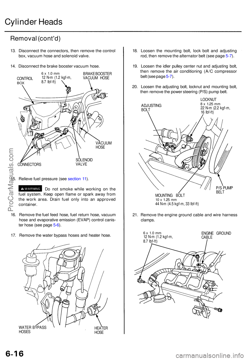
13. Disconnec t th e connectors , the n remov e th e contro l
box , vacuu m hos e an d solenoi d valve .
14 . Disconnec t th e brak e booste r vacuu m hose .
CONTRO LBOX
6 x 1. 0 m m12 N- m (1. 2 kgf-m ,
8. 7 Ibf-ft ) BRAK
E BOOSTE R
VACUU M HOS E
VACUU MHOSE
CONNECTOR S SOLENOI
D
VALVE
15. Reliev e fue l pressur e (se e sectio n 11 ).
D o no t smok e whil e workin g o n th e
fue l system . Kee p ope n flam e o r spar k awa y fro m
th e wor k area . Drai n fue l onl y int o a n approve d
container .
16 . Remov e th e fue l fee d hose , fue l retur n hose , vacuu m
hos e an d evaporativ e emissio n (EVAP ) contro l canis -
te r hos e (se e pag e 5-6 ).
17 . Remov e th e wate r bypas s hose s an d heate r hose .
WATE R BYPAS S
HOSE SHEATE RHOSE
18. Loose n th e mountin g bolt , loc k bol t an d adjustin g
rod , the n remov e th e alternato r bel t (se e pag e 5-7 ).
19 . Loose n th e idle r pulle y cente r nu t an d adjustin g bolt ,
the n remov e th e ai r conditionin g (A/ C compresso r
bel t (se e pag e 5-7 ).
20 . Loose n th e adjustin g bolt , locknu t an d mountin g bolt ,
the n remov e th e powe r steerin g (P/S ) pum p belt .
ADJUSTIN GBOLT LOCKNU
T
8 x 1.2 5 mm22 N- m (2. 2 kgf-m ,
1 6 Ibf-ft )
P/S PUM PBELTMOUNTIN G BOL T10 x 1.2 5 mm44 N- m (4. 5 kgf-m , 3 3 Ibf-ft )
21. Remov e th e engine ground cabl e an d wir e harnes s
clamps.
6 x 1. 0 m m12 N- m (1. 2 kgf-m ,
8. 7 Ibf-ft ) ENGIN
E GROUN DCABLE
ProCarManuals.com
Page 116 of 1771
Pistons
Installation
Before installing the piston, apply a coat of engine
oil to the ring grooves and cylinder bores.
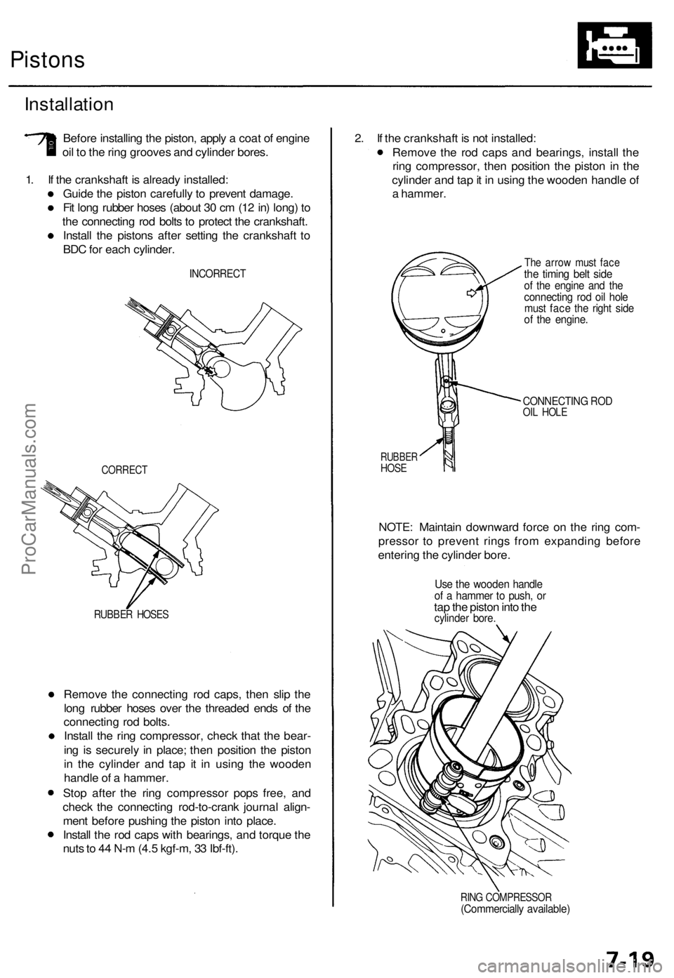
1. If the crankshaft is already installed:
Guide the piston carefully to prevent damage.
Fit long rubber hoses (about 30 cm (12 in) long) to
the connecting rod bolts to protect the crankshaft.
Install the pistons after setting the crankshaft to
BDC for each cylinder.
INCORRECT
CORRECT
RUBBER HOSES
Remove the connecting rod caps, then slip the
long rubber hoses over the threaded ends of the
connecting rod bolts.
Install the ring compressor, check that the bear-
ing is securely in place; then position the piston
in the cylinder and tap it in using the wooden
handle of a hammer.
Stop after the ring compressor pops free, and
check the connecting rod-to-crank journal align-
ment before pushing the piston into place.
Install the rod caps with bearings, and torque the
nuts to 44 N-m (4.5 kgf-m, 33 Ibf-ft).
2. If the crankshaft is not installed:
Remove the rod caps and bearings, install the
ring compressor, then position the piston in the
cylinder and tap it in using the wooden handle of
a hammer.
The arrow must face
the timing belt side
of the engine and the
connecting rod oil hole
must face the right side
of the engine.
CONNECTING ROD
OIL HOLE
RUBBER
HOSE
NOTE: Maintain downward force on the ring com-
pressor to prevent rings from expanding before
entering the cylinder bore.
Use the wooden handle
of a hammer to push, or
tap the piston into the
cylinder bore.
RING COMPRESSOR
(Commercially available)ProCarManuals.com
Page 467 of 1771
Inspection an d Adjustmen t
Pump Bel t
NOTE : Whe n usin g a ne w belt , firs t adjus t th e deflectio n
o r tensio n t o th e value s fo r th e ne w belt , the n readjus t
th e deflectio n o r tensio n t o th e value s fo r th e use d bel t
afte r runnin g engin e fo r fiv e minutes .
Inspectio n
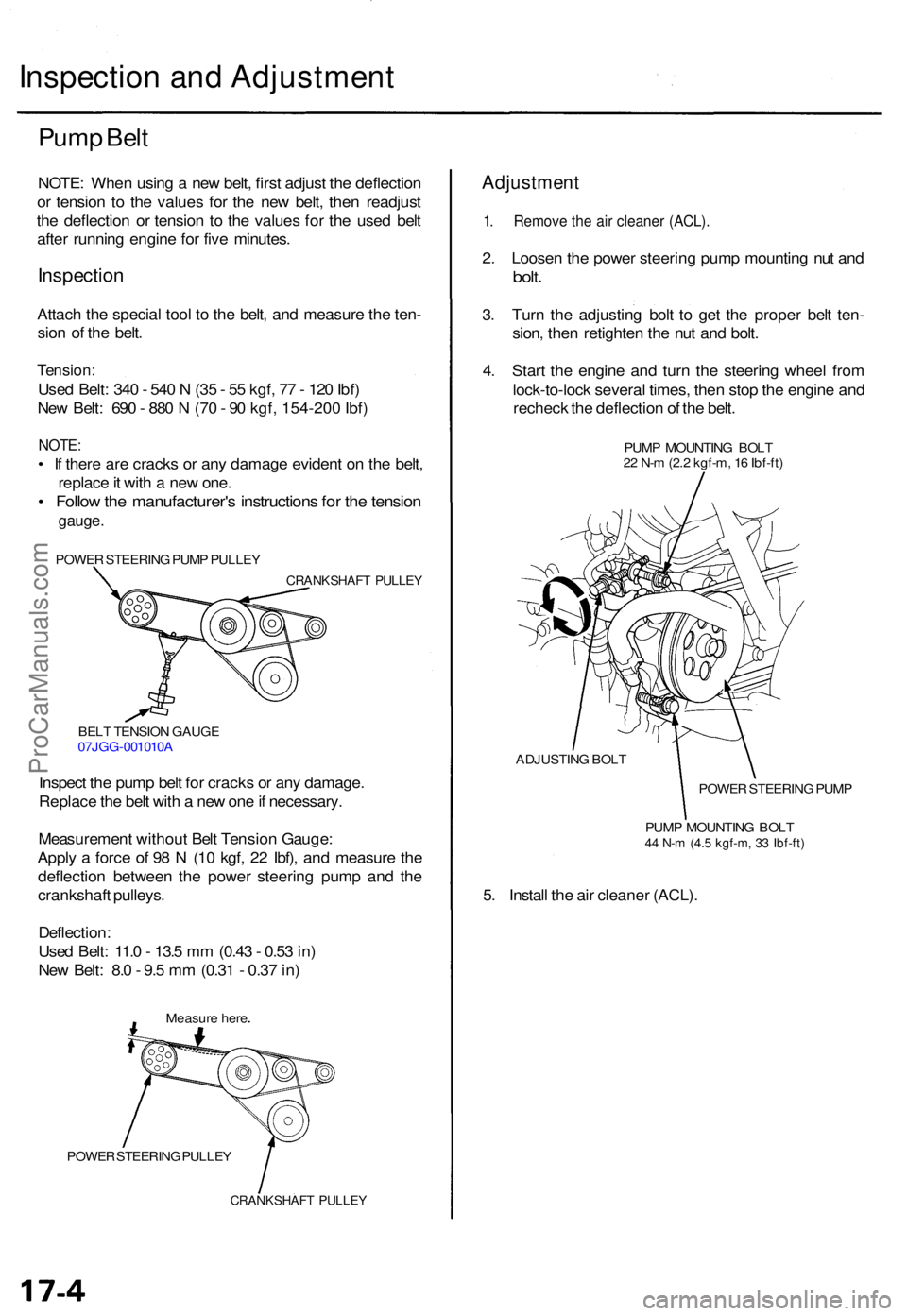
Attach th e specia l too l t o th e belt , an d measur e th e ten -
sio n o f th e belt .
Tension :
Used Belt : 34 0 - 54 0 N (3 5 - 5 5 kgf , 7 7 - 12 0 Ibf )
Ne w Belt : 69 0 - 88 0 N (7 0 - 9 0 kgf , 154-20 0 Ibf )
NOTE :
• I f ther e ar e crack s o r an y damag e eviden t o n th e belt ,
replac e it wit h a ne w one .
• Follo w th e manufacturer' s instruction s fo r th e tensio n
gauge .
POWE R STEERIN G PUM P PULLE Y
CRANKSHAF T PULLE Y
BELT TENSIO N GAUG E
07JG G-001010 A
Inspect th e pum p bel t fo r crack s o r an y damage .
Replac e th e bel t wit h a ne w on e if necessary .
Measuremen t withou t Bel t Tensio n Gauge :
Appl y a forc e o f 9 8 N (1 0 kgf , 2 2 Ibf) , an d measur e th e
deflectio n betwee n th e powe r steerin g pum p an d th e
crankshaf t pulleys .
Deflection :
Use d Belt : 11. 0 - 13. 5 m m (0.4 3 - 0.5 3 in )
Ne w Belt : 8. 0 - 9. 5 m m (0.3 1 - 0.3 7 in )
Measur e her e
POWE R STEERIN G PULLE Y
CRANKSHAF T PULLE Y
Adjustmen t
1. Remov e th e ai r cleane r (ACL) .
2. Loose n th e powe r steerin g pum p mountin g nu t an d
bolt .
3. Tur n th e adjustin g bol t t o ge t th e prope r bel t ten -
sion , the n retighte n th e nu t an d bolt .
4 . Star t th e engin e an d tur n th e steerin g whee l fro m
lock-to-loc k severa l times , the n sto p th e engin e an d
rechec k th e deflectio n o f th e belt .
PUM P MOUNTIN G BOL T
2 2 N- m (2. 2 kgf-m , 1 6 Ibf-ft )
ADJUSTIN G BOL T
POWER STEERIN G PUM P
PUM P MOUNTIN G BOL T
44 N- m (4. 5 kgf-m , 3 3 Ibf-ft )
5. Instal l th e ai r cleane r (ACL) .
ProCarManuals.com
Page 566 of 1771
A/C Compresso r Bel t
Adjustmen t
Deflection Metho d
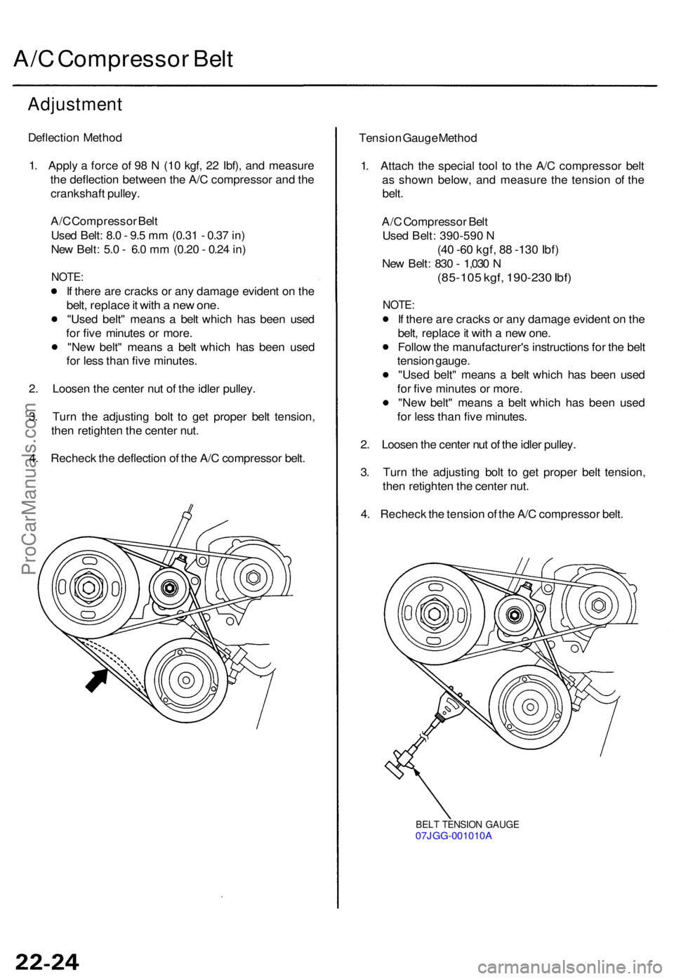
1 . Appl y a forc e o f 9 8 N (1 0 kgf , 2 2 Ibf) , an d measur e
th e deflectio n betwee n th e A/ C compresso r an d th e
crankshaf t pulley .
A/ C Compresso r Bel t
Use d Belt : 8. 0 - 9. 5 m m (0.3 1 - 0.3 7 in )
Ne w Belt : 5. 0 - 6. 0 m m (0.2 0 - 0.2 4 in )
NOTE :
If ther e ar e crack s o r an y damag e eviden t o n th e
belt , replac e it wit h a ne w one .
"Use d belt " mean s a bel t whic h ha s bee n use d
fo r fiv e minute s o r more .
"New belt" mean s a bel t whic h ha s bee n use d
fo r les s tha n fiv e minutes .
2 . Loose n th e cente r nu t o f th e idle r pulley .
3 . Tur n th e adjustin g bol t t o ge t prope r bel t tension ,
the n retighte n th e cente r nut .
4 . Rechec k th e deflectio n o f th e A/ C compresso r belt . Tensio
n Gaug e Metho d
1 . Attac h th e specia l too l t o th e A/ C compresso r bel t
a s show n below , an d measur e th e tensio n o f th e
belt .
A/ C Compresso r Bel t
Use d Belt : 390-59 0 N
(4 0 -6 0 kgf , 88 -13 0 Ibf )
New Belt : 83 0 - 1,03 0 N
(85-10 5 kgf , 190-23 0 Ibf )
NOTE :
If ther e ar e crack s o r an y damag e eviden t o n th e
belt , replac e it wit h a ne w one .
Follo w th e manufacturer' s instruction s fo r th e bel t
tensio n gauge .
"Use d belt " mean s a bel t whic h ha s bee n use d
fo r fiv e minute s o r more .
"Ne w belt " mean s a bel t whic h ha s bee n use d
fo r les s tha n fiv e minutes .
2 . Loose n th e cente r nu t o f th e idle r pulley .
3 . Tur n th e adjustin g bol t t o ge t prope r bel t tension ,
the n retighte n th e cente r nut .
4 . Rechec k th e tensio n o f th e A/ C compresso r belt .
BEL T TENSIO N GAUG E07JGG-001010 A
ProCarManuals.com
Page 608 of 1771
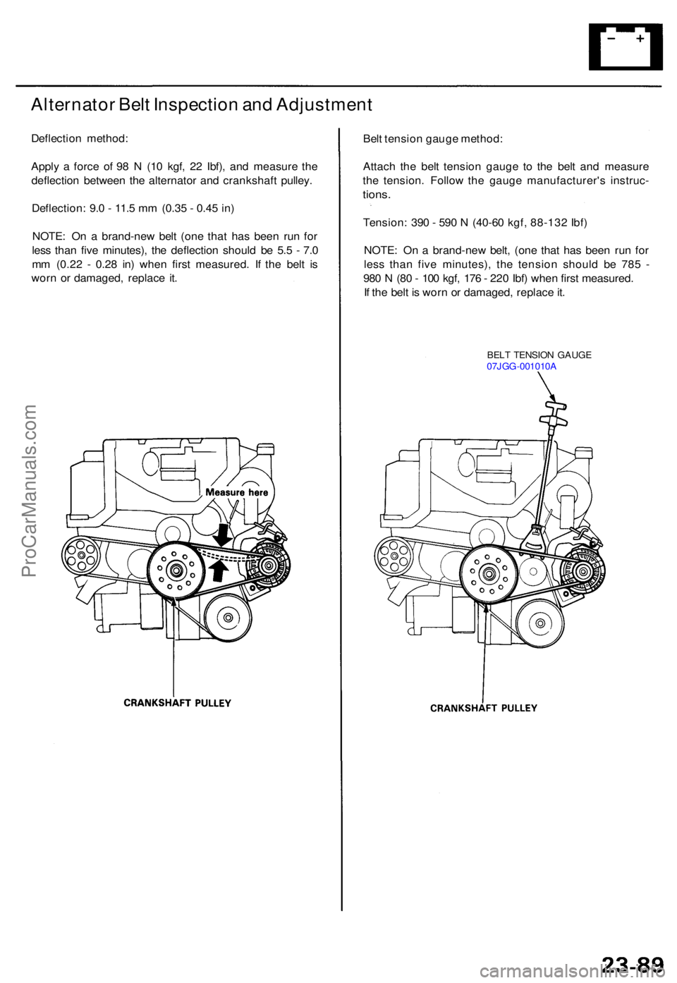
Alternator Bel t Inspectio n an d Adjustmen t
Deflection method :
Appl y a forc e o f 9 8 N (1 0 kgf , 2 2 Ibf) , an d measur e th e
deflectio n betwee n th e alternato r an d crankshaf t pulley .
Deflection : 9. 0 - 11. 5 m m (0.3 5 - 0.4 5 in )
NOTE : O n a brand-ne w bel t (on e tha t ha s bee n ru n fo r
les s tha n fiv e minutes) , th e deflectio n shoul d b e 5. 5 - 7. 0
m m (0.2 2 - 0.2 8 in ) whe n firs t measured . I f th e bel t i s
wor n o r damaged , replac e it . Bel
t tensio n gaug e method :
Attac h th e bel t tensio n gaug e t o th e bel t an d measur e
th e tension . Follo w th e gaug e manufacturer' s instruc -
tions.
Tension : 39 0 - 59 0 N (4 0-6 0 kgf , 88-13 2 Ibf )
NOTE : O n a brand-ne w belt , (on e tha t ha s bee n ru n fo r
les s tha n fiv e minutes) , th e tensio n shoul d b e 78 5 -
98 0 N (8 0 - 10 0 kgf , 17 6 - 22 0 Ibf ) whe n firs t measured .
I f th e bel t i s wor n o r damaged , replac e it .
BEL T TENSIO N GAUG E
07JG G-001010 A
ProCarManuals.com
Page 681 of 1771
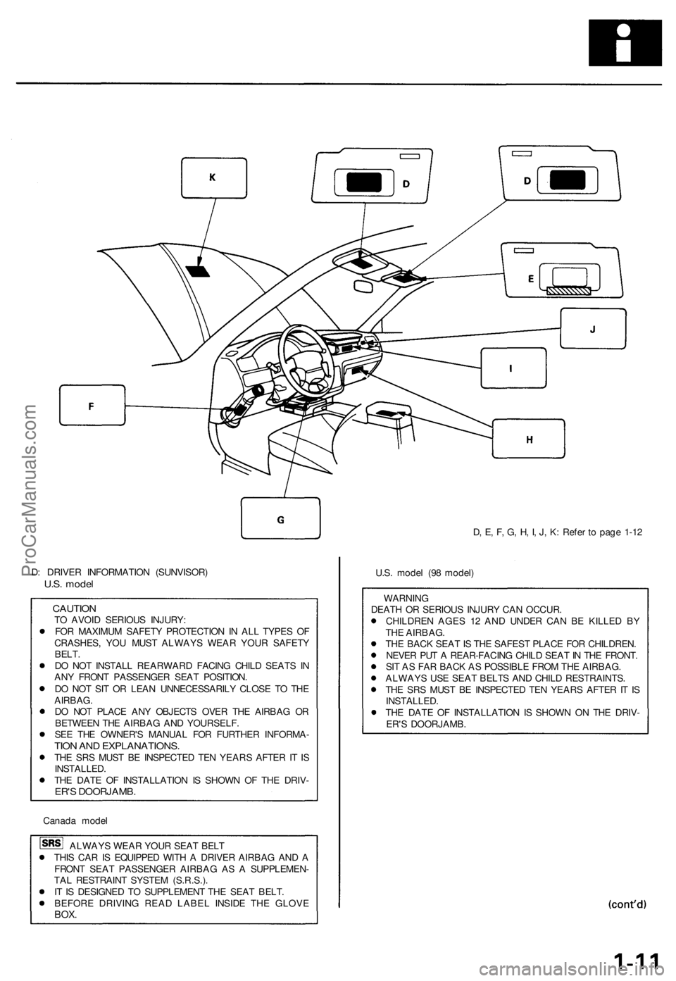
D, E, F, G, H, I, J, K: Refer to page 1-12
D: DRIVER INFORMATION (SUNVISOR)
U.S. model
CAUTION
TO AVOID SERIOUS INJURY:
FOR MAXIMUM SAFETY PROTECTION IN ALL TYPES OF
CRASHES, YOU MUST ALWAYS WEAR YOUR SAFETY
BELT.
DO NOT INSTALL REARWARD FACING CHILD SEATS IN
ANY FRONT PASSENGER SEAT POSITION.
DO NOT SIT OR LEAN UNNECESSARILY CLOSE TO THE
AIRBAG.
DO NOT PLACE ANY OBJECTS OVER THE AIRBAG OR
BETWEEN THE AIRBAG AND YOURSELF.
SEE THE OWNER'S MANUAL FOR FURTHER INFORMA-
TION AND EXPLANATIONS.
THE SRS MUST BE INSPECTED TEN YEARS AFTER IT IS
INSTALLED.
THE DATE OF INSTALLATION IS SHOWN OF THE DRIV-
ER'S DOORJAMB.
Canada model
ALWAYS WEAR YOUR SEAT BELT
THIS CAR IS EQUIPPED WITH A DRIVER AIRBAG AND A
FRONT SEAT PASSENGER AIRBAG AS A SUPPLEMEN-
TAL RESTRAINT SYSTEM (S.R.S.).
IT IS DESIGNED TO SUPPLEMENT THE SEAT BELT.
BEFORE DRIVING READ LABEL INSIDE THE GLOVE
BOX.
U.S. model (98 model)
WARNING
DEATH OR SERIOUS INJURY CAN OCCUR.
CHILDREN AGES 12 AND UNDER CAN BE KILLED BY
THE AIRBAG.
THE BACK SEAT IS THE SAFEST PLACE FOR CHILDREN.
NEVER PUT A REAR-FACING CHILD SEAT IN THE FRONT.
SIT AS FAR BACK AS POSSIBLE FROM THE AIRBAG.
ALWAYS USE SEAT BELTS AND CHILD RESTRAINTS.
THE SRS MUST BE INSPECTED TEN YEARS AFTER IT IS
INSTALLED.
THE DATE OF INSTALLATION IS SHOWN ON THE DRIV-
ER'S DOORJAMB.ProCarManuals.com
Page 682 of 1771
Warning/Caution Label Locations
(cont'd)
D: DRIVER INFORMATION (SUNVISOR)
Canada model (98 model)
CAUTION
TO AVOID SERIOUS INJURY:
FOR MAXIMUM SAFETY PROTECTION IN ALL TYPES OF
CRASHES, YOU MUST ALWAYS WEAR YOUR SAFETY
BELT.
DO NOT INSTALL REARWARD FACING CHILD SEATS IN
ANY FRONT PASSENGER SEAT POSITION.
DO NOT SIT OR LEAN UNNECESSARILY CLOSE TO THE
AIRBAG.
DO NOT PLACE ANY OBJECTS OVER THE AIRBAG OR
BETWEEN THE AIRBAG AND YOURSELF.
SEE THE OWNER'S MANUAL FOR FURTHER INFORMA-
TION AND EXPLANATIONS.
THE SRS MUST BE INSPECTED TEN YEARS AFTER IT IS
INSTALLED.
THE DATE OF INSTALLATION IS SHOWN OF THE DRIV-
ER'S DOORJAMB.
E: ASSISTANT INFORMATION
U.S. model
AIRBAG SEE OTHER SIDE.
U.S. model (98 model)
AIRBAG WARNING
FLIP VISOR OVER
F: STEERING COLUMN NOTICE
NOTICE
TO PREVENT SRS DAMAGE, REMOVE STEERING WHEEL
BEFORE REMOVING STEERING SHAFT CONNECTING
BOLT.
G: MONITOR NOTICE
NOTICE
• NO SERVICEABLE PARTS INSIDE.
• REFER TO SERVICE MANUAL FOR DETAILED INSTRUC-
TIONS.
H: SRS CONSOLE/GLOVE BOX INFORMATION
Canada model (95 - 97 model)
AIRBAG INFORMATION
SUPPLEMENTAL RESTRAINT SYSTEM (SRS)
• THE SRS MUST BE INSPECTED TEN YEARS AFTER IT IS
INSTALLED. THE DATE OF INSTALLATION IS SHOWN
ON THE CERTIFICATION PLATE, LOCATED ON THE
DRIVER'S DOORJAMB.
• DIAGNOSTIC CHECKS AND REPLACEMENT OF SRS
COMPONENTS MUST BE DONE BY AN AUTHORIZED
DEALER.
• SEE YOUR OWNER'S MANUAL FOR ADDITIONAL SRS
INFORMATION.
I: FRONT SEAT PASSENGER AIRBAG MODULE DANGER
DANGER
EXPLOSIVE/FLAMMABLE
CONTACT WITH ACID, WATER OR HEAVY METALS SUCH
AS COPPER, LEAD OR MERCURY MAY PRODUCE HARM-
FUL AND IRRITATING GASES OR EXPLOSIVE COM-
POUNDS. STORAGE TEMPERATURES MUST NOT EXCEED
200 F (100°C). FOR PROPER HANDLING, STORAGE AND
DISPOSAL PROCEDURES REFER TO SERVICE MANUAL,
SRS SUPPLEMENT.
POISON
CONTAINS POISONOUS SODIUM AZIDE AND POTASSIUM
NITRATE.
FIRST AID
IF CONTENTS ARE SWALLOWED, INDUCE VOMITING.
FOR EYE CONTACT, FLUSH EYES WITH WATER FOR 15
MINUTES. IF GASES (FROM ACID OR WATER CONTACT)
ARE INHALED, SEEK FRESH AIR. IN EVERY CASE, GET
PROMPT MEDICAL ATTENTION.
KEEP OUT OF REACH OF CHILDREN.
WARNING
THE AIRBAG INFLATOR IS EXPLOSIVE AND, IF ACCIDEN-
TALLY DEPLOYED, CAN SERIOUSLY HURT OR KILL YOU.
• DO NOT USE ELECTRICAL TEST EQUIPMENT OR PROB-
ING DEVICES. THEY CAN CAUSE ACCIDENTAL DEPLOY-
MENT.
• NO SERVICEABLE PARTS INSIDE. DO NOT DISASSEM-
BLE.
• PLACE AIRBAG UPRIGHT WHEN REMOVED.
• FOLLOW SERVICE MANUAL INSTRUCTIONS CAREFULLY.
J: PASSENGER AIRBAG CAUTION
U.S. model (98 model)
WARNING
CHILDREN CAN BE KILLED OR INJURED BY A PASSENGER
AIRBAG.
THE BACK SEAT IS THE SAFEST PLACE FOR CHILDREN
AGES 12 AND UNDER. MAKE SURE ALL CHILDREN USE
SEAT BELTS OR CHILD SEATS.
K: SRS WARNING (HOOD)
SUPPLEMENTAL RESTRAINT SYSTEM (SRS)
THIS VEHICLE IS EQUIPPED WITH DRIVER AND FRONT
SEAT PASSENGER AIRBAGS.
ALL SRS ELECTRICAL WIRING AND CONNECTORS ARE
COLORED YELLOW.
TAMPERING WITH, DISCONNECTING OR USING ELECTRI-
CAL TEST EQUIPMENT ON THE SRS WIRING CAN MAKE
THE SYSTEM INOPERATIVE OR CAUSE ACCIDENTAL FIR-
ING OF THE INFLATOR.
WARNING
THE AIRBAG INFLATOR IS EXPLOSIVE AND, IF ACCIDEN-
TALLY DEPLOYED, CAN SERIOUSLY HURT YOU. FOLLOW
SERVICE MANUAL INSTRUCTIONS CAREFULLY.ProCarManuals.com
Page 720 of 1771
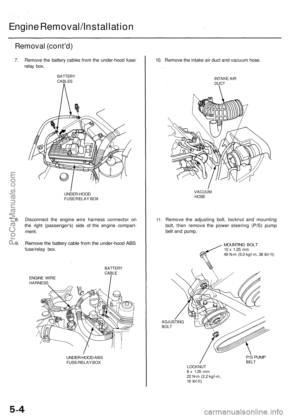
Engine Removal/Installation
Removal (cont'd)
7. Remove the battery cables from the under-hood fuse/
relay box.
BATTERY
CABLES
8.
9.
UNDER-HOOD
FUSE/RELAY BOX
Disconnect the engine wire harness connector on
the right (passenger's) side of the engine compart-
ment.
Remove the battery cable from the under-hood ABS
fuse/relay box.
BATTERY
CABLE
ENGINE WIRE
HARNESS
UNDER-HOOD ABS
FUSE/RELAY BOX
10. Remove the intake air duct and vacuum hose.
INTAKE AIR
DUCT
11.
VACUUM
HOSE
Remove the adjusting bolt, locknut and mounting
bolt, then remove the power steering (P/S) pump
belt and pump.
MOUNTING BOLT
10 x
1.25
mm
49 N-m (5.0 kgf-m, 36 Ibf-ft)
ADJUSTING
BOLT
P/S PUMP
BELT
LOCKNUT
8 x
1.25
mm
22 N-m (2.2 kgf-m,
16 Ibf-ft)ProCarManuals.com