1995 ACURA TL belt
[x] Cancel search: beltPage 750 of 1771
Cylinder Hea d
Remova l
Engine remova l i s no t require d fo r thi s procedure .
Mak e sur e jack s an d safet y stand s ar e
place d properl y an d hois t bracket s ar e attache d to cor -
rec t positio n o n th e engine .
CAUTION :
• Us e fende r cover s t o avoi d damagin g painte d sur -
faces .
• Unplu g th e wirin g connector s carefull y whil e holdin g
th e connecto r portio n to avoi d damage .
• T o avoi d damagin g th e cylinde r head , wai t unti l th e
engin e coolan t temperatur e drop s belo w 100° F
(38°C ) befor e loosenin g th e retainin g bolts .
NOTE :
• Mar k al l wirin g an d hose s t o avoi d misconnection .
Also , b e sur e tha t the y d o no t contac t othe r wirin g o r
hoses , o r interfer e wit h othe r parts .
• Inspec t th e timin g bel t befor e removin g th e cylinde r
head .
• Tur n th e crankshaf t pulle y s o tha t th e No . 1 pisto n i s
a t to p dea d cente r (se e pag e 6-12 ).
1 . Mak e sur e yo u hav e th e anti-thef t cod e fo r th e radio ,
the n writ e dow n th e frequencie s fo r th e radio' s pre -
se t buttons .
2 . Disconnec t th e negativ e termina l fro m th e battery .
3 . Drai n th e engin e coolan t (se e pag e 10-5 ).
Remov e th e radiato r cap to spee d draining .
4 . Remov e th e groun d cabl e an d ignitio n coi l wire .
IGNITIO N COI LWIRE6 x 1. 0 m m9.8 N- m (1. 0 kgf-m ,
7. 2 Ibf-ft )
GROUN DCABLE
5. Remov e th e hea t shield s (se e pag e 5-3 ).
6 . Remov e th e intak e ai r duc t (se e pag e 5-4 ).
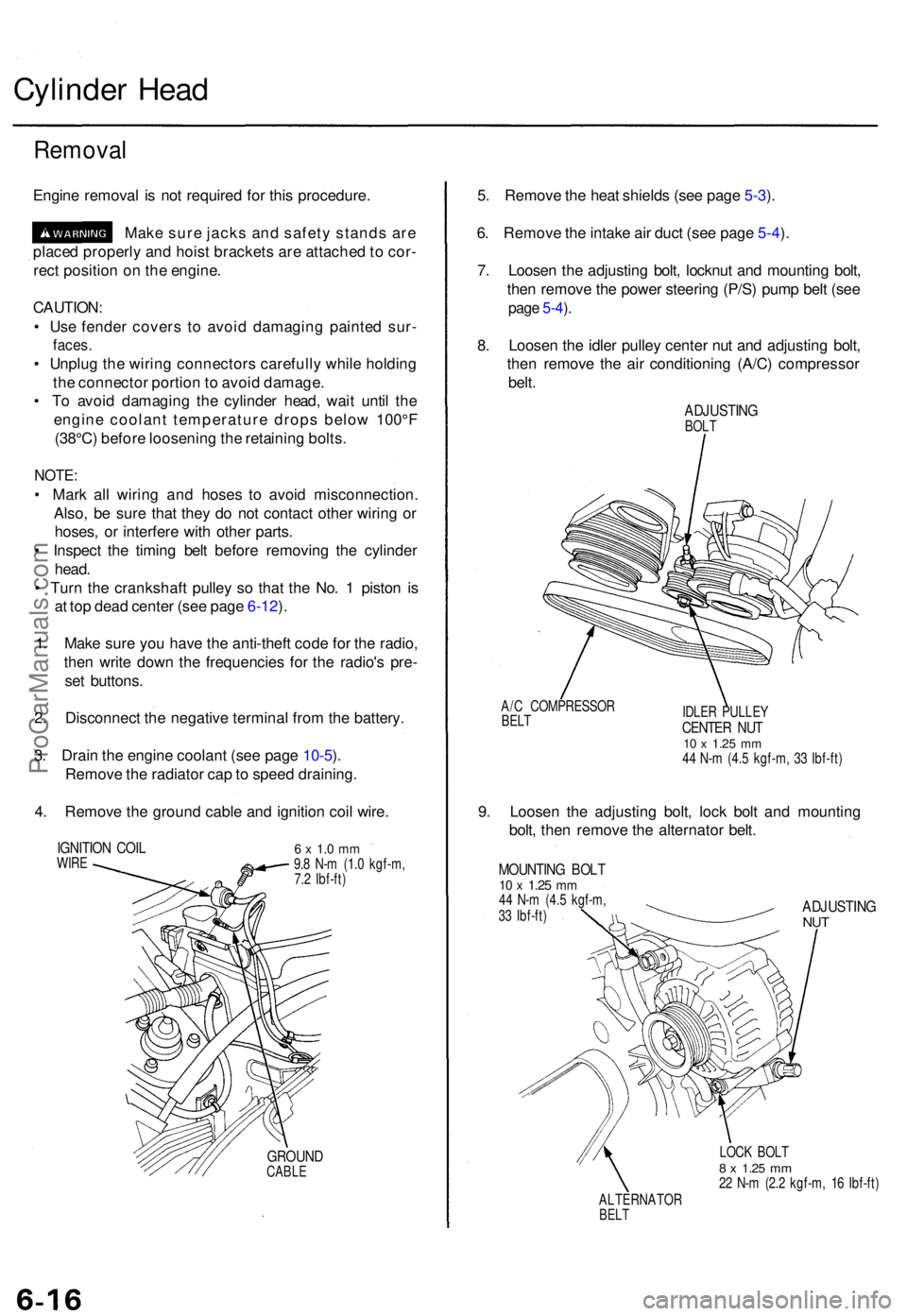
7 . Loose n th e adjustin g bolt , locknu t an d mountin g bolt ,
the n remov e th e powe r steerin g (P/S ) pum p bel t (se e
page 5-4 ).
8 . Loose n th e idle r pulle y cente r nu t an d adjustin g bolt ,
the n remov e th e ai r conditionin g (A/C ) compresso r
belt .
ADJUSTIN GBOLT
A/ C COMPRESSO R
BELTIDLE R PULLE YCENTER NU T10 x 1.2 5 mm44 N- m (4. 5 kgf-m , 3 3 Ibf-ft )
9. Loose n th e adjustin g bolt , loc k bol t an d mountin g
bolt , the n remov e th e alternato r belt .
MOUNTIN G BOL T10 x 1.2 5 mm44 N- m (4. 5 kgf-m ,
3 3 Ibf-ft )ADJUSTIN GNUT
LOC K BOL T8 x 1.2 5 mm22 N- m (2. 2 kgf-m , 1 6 Ibf-ft )
ALTERNATO R
BELT
ProCarManuals.com
Page 798 of 1771
Pistons
Installation
Before installing the piston, apply a coat of
engine oil to the ring grooves and cylinder
bores.
1. If the crankshaft is already installed:
Remove the connecting rod caps and slip short
sections of rubber hose over the threaded ends
of the connecting rod bolts.
Install the ring compressor, check that the bear-
ing is securely in place, then position the piston
in the cylinder and tap it in using the wooden
handle of a hammer.
Stop tapping after the ring compressor pops
free, and check the connecting rod-to-crank jour-
nal alignment before pushing piston into place.
Install the rod caps with bearings, and torque the
nuts to 32 N-m (3.3 kgf-m, 24 Ibf-ft)
2. If the crankshaft is not installed:
Remove the rod caps and bearings, install the
ring compressor, then position the piston in the
cylinder and tap it in using the wooden handle of
a hammer.
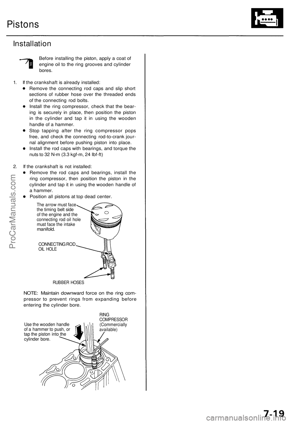
Position all pistons at top dead center.
The arrow must face
the timing belt side
of the engine and the
connecting rod oil hole
must face the intake
manifold.
CONNECTING ROD
OIL HOLE
RUBBER HOSES
NOTE: Maintain downward force on the ring com-
pressor to prevent rings from expanding before
entering the cylinder bore.
Use the wooden handle
of a hammer to push, or
tap the piston into the
cylinder bore.
RING
COMPRESSOR
(Commercially
available)ProCarManuals.com
Page 1146 of 1771
Steering Pum p
Constructio n
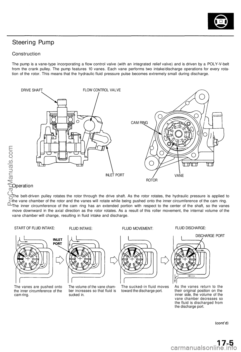
The pum p is a vane-typ e incorporatin g a flo w contro l valv e (wit h a n integrate d relie f valve ) an d i s drive n b y a POLY-V-bel t
fro m th e cran k pulley . Th e pum p feature s 1 0 vanes . Eac h van e perform s tw o intake/discharg e operation s fo r ever y rota -
tio n o f th e rotor . Thi s mean s tha t th e hydrauli c flui d pressur e puls e become s extremel y smal l durin g discharge .
DRIVE SHAF TFLOW CONTRO L VALV E
CAM RIN G
INLE T POR TVANE
ROTO R
Operatio n
The belt-drive n pulle y rotate s th e roto r throug h th e driv e shaft . A s th e roto r rotates , th e hydrauli c pressur e i s applie d t o
th e van e chambe r o f th e roto r an d th e vane s wil l rotat e whil e bein g pushe d ont o th e inne r circumferenc e o f th e ca m ring .
Th e inne r circumferenc e o f th e ca m rin g ha s a n extende d portio n wit h respec t t o th e cente r o f th e shaft , s o th e vane s
mov e downwar d i n th e axia l directio n a s th e roto r rotates . A s a resul t o f thi s rolle r movement , th e interna l volum e o f th e
van e chambe r wil l change , resultin g i n flui d intak e an d discharge .
START O F FLUI D INTAKE :FLUID INTAKE :FLUID MOVEMENT :FLUID DISCHARGE :
DISCHARGE POR T
The vane s ar e pushe d ont othe inne r circumferenc e o f th ecam ring .
The volum e o f th e van e cham -ber increase s s o tha t flui d i ssucke d in .
Th e sucked-i n flui d move stoward th e discharg e port .As th e vane s retur n t o th ethei r origina l positio n o n th einne r side , th e volum e o f th evan e chambe r decrease s s othe flui d i s discharge d fro mthe discharg e port .
ProCarManuals.com
Page 1157 of 1771
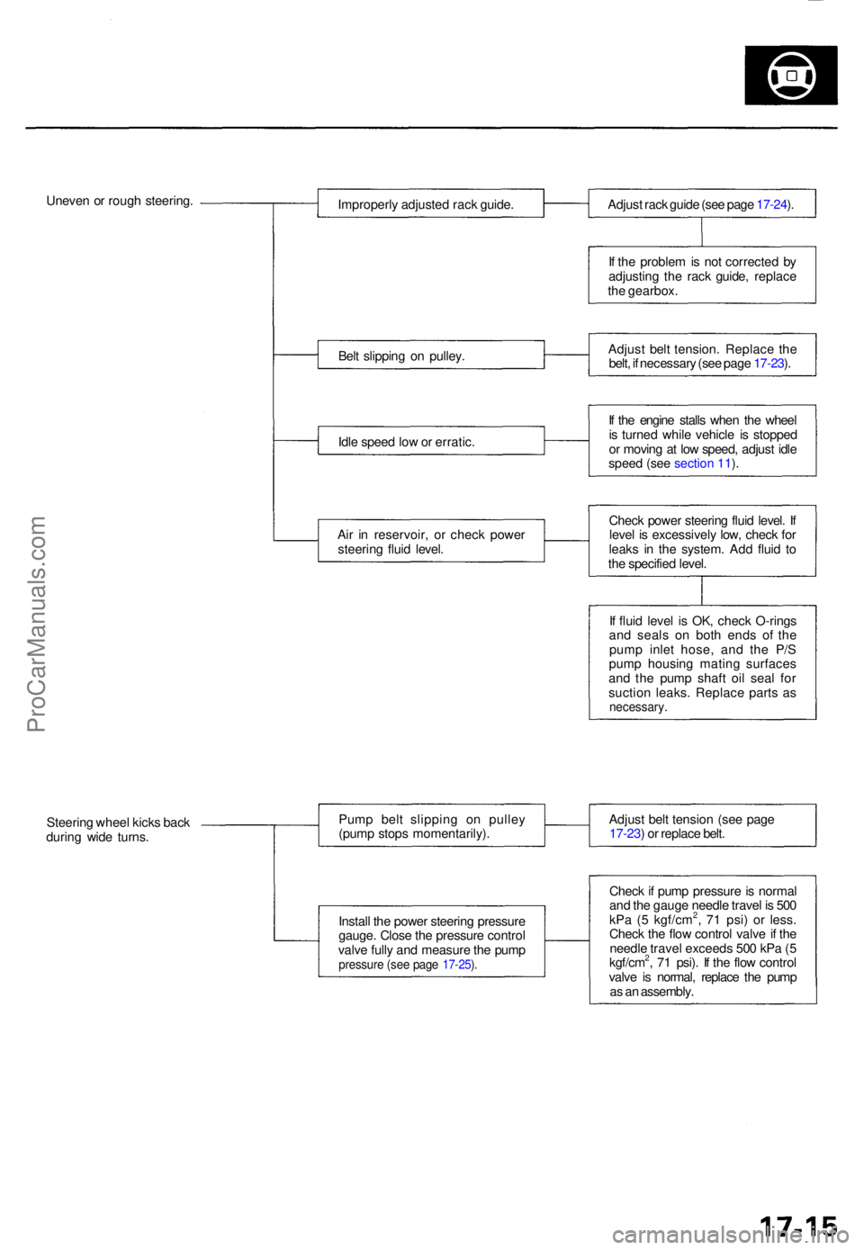
Uneven o r roug h steering .
Improperly adjuste d rac k guide .
Bel t slippin g o n pulley .
Idl e spee d lo w o r erratic .
Ai r i n reservoir , o r chec k powe r
steerin g flui d level . Adjus
t rac k guid e (se e pag e 17-24 ).
I f th e proble m is no t correcte d b y
adjustin g th e rac k guide , replac e
th e gearbox .
Adjus t bel t tension . Replac e th e
belt , i f necessar y (se e pag e 17-23 ).
I f th e engin e stall s whe n th e whee l
i s turne d whil e vehicl e i s stoppe d
o r movin g a t lo w speed , adjus t idl e
speed (see section 11).
Check powe r steerin g flui d level . I f
leve l i s excessivel y low , chec k fo r
leak s i n th e system . Ad d flui d t o
th e specifie d level .
I f flui d leve l i s OK , chec k O-ring s
an d seal s o n bot h end s o f th e
pum p inle t hose , an d th e P/ S
pum p housin g matin g surface s
an d th e pum p shaf t oi l sea l fo r
suctio n leaks . Replac e part s a s
necessary .
Steering whee l kick s bac k
durin g wid e turns . Pum
p bel t slippin g o n pulle y
(pum p stop s momentarily) .
Instal l th e powe r steerin g pressur e
gauge . Clos e th e pressur e contro l
valv e full y an d measur e th e pum p
pressur e (se e pag e 17-25 ).
Adjus t bel t tensio n (se e pag e
17-23 ) o r replac e belt .
Chec k if pum p pressur e is norma l
an d th e gaug e needl e trave l i s 50 0
kP a ( 5 kgf/cm
2, 7 1 psi ) o r less .
Chec k th e flo w contro l valv e if th e
needl e trave l exceed s 50 0 kP a ( 5
kgf/cm
2, 7 1 psi) . I f th e flo w contro l
valv e i s normal , replac e th e pum p
a s a n assembly .
ProCarManuals.com
Page 1158 of 1771
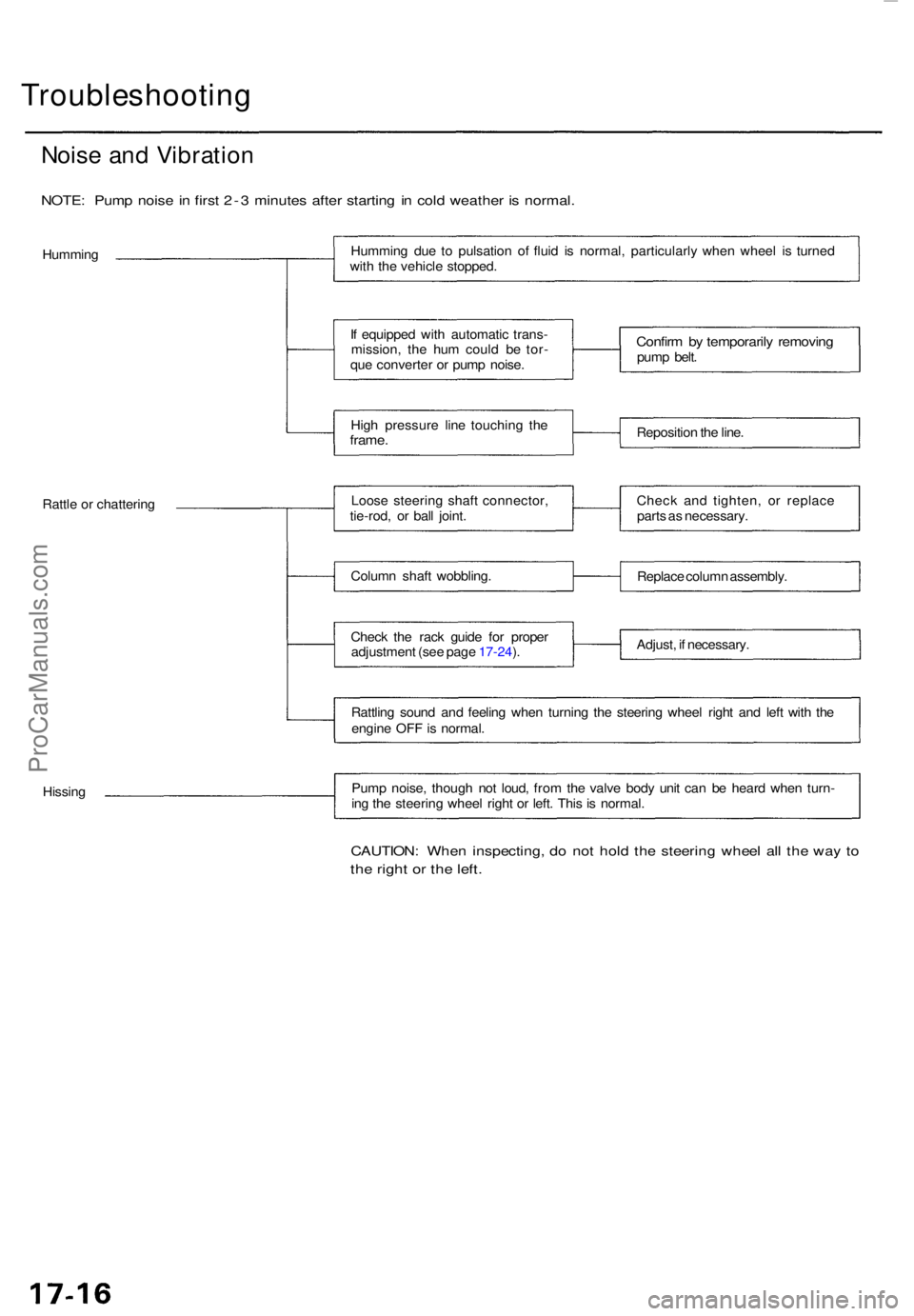
Troubleshooting
Noise an d Vibratio n
NOTE: Pum p nois e in firs t 2- 3 minute s afte r startin g i n col d weathe r i s normal .
Hummin g Hummin
g du e t o pulsatio n o f flui d i s normal , particularl y whe n whee l i s turne d
wit h th e vehicl e stopped .
I f equippe d wit h automati c trans -
mission , th e hu m coul d b e tor -
qu e converte r o r pum p noise .
Hig h pressur e lin e touchin g th e
frame .
Confir m b y temporaril y removin gpump belt .
Repositio n th e line .
Rattl e o r chatterin g Loos
e steerin g shaf t connector ,
tie-rod , o r bal l joint .
Colum n shaf t wobbling .
Chec k th e rac k guid e fo r prope r
adjustmen t (se e pag e 17-24 ). Chec
k an d tighten , o r replac e
part s a s necessary .
Replac e colum n assembly .
Adjust , i f necessary .
Rattlin g soun d an d feelin g whe n turnin g th e steerin g whee l righ t an d lef t wit h th e
engin e OF F is normal .
Hissin g Pum
p noise , thoug h no t loud , fro m th e valv e bod y uni t ca n b e hear d whe n turn -
in g th e steerin g whee l righ t o r left . Thi s is normal .
CAUTION : Whe n inspecting , d o no t hol d th e steerin g whee l al l th e wa y t o
th e righ t o r th e left .
ProCarManuals.com
Page 1159 of 1771
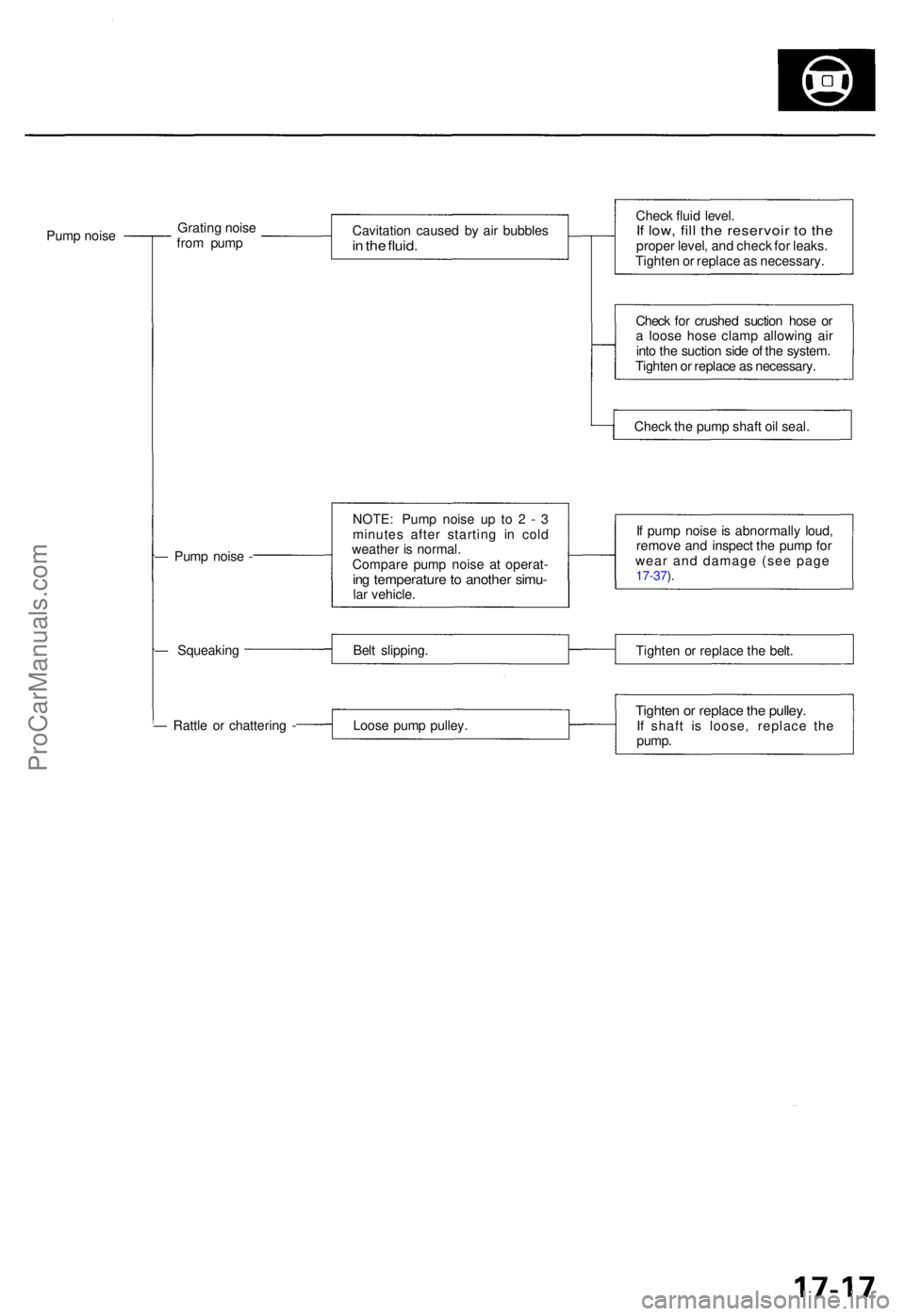
Pump nois e Gratin
g nois e
fro m pum p Cavitatio
n cause d b y ai r bubble sin th e fluid .
Chec k flui d level .If low , fil l th e reservoi r t o th eprope r level , an d chec k fo r leaks .
Tighte n o r replace as necessary .
Chec k fo r crushe d suctio n hos e o r
a loos e hos e clam p allowin g ai r
int o th e suctio n sid e o f th e system .
Tighte n o r replac e a s necessary .
Chec k th e pum p shaf t oi l seal .
— Pum p nois e - NOTE
: Pum p nois e u p t o 2 - 3
minute s afte r startin g i n col d
weathe r i s normal .
Compar e pum p nois e a t operat -
ing temperatur e to anothe r simu -lar vehicle . I
f pum p nois e is abnormall y loud ,
remov e an d inspec t th e pum p fo r
wear and damage (see page
17-37 ).
— Squeakin g Belt slipping .
Tighten o r replac e th e belt .
— Rattl e o r chatterin g - Loose pum p pulley .
Tighten o r replac e th e pulley .If shaf t i s loose , replac e th e
pump .
ProCarManuals.com
Page 1165 of 1771
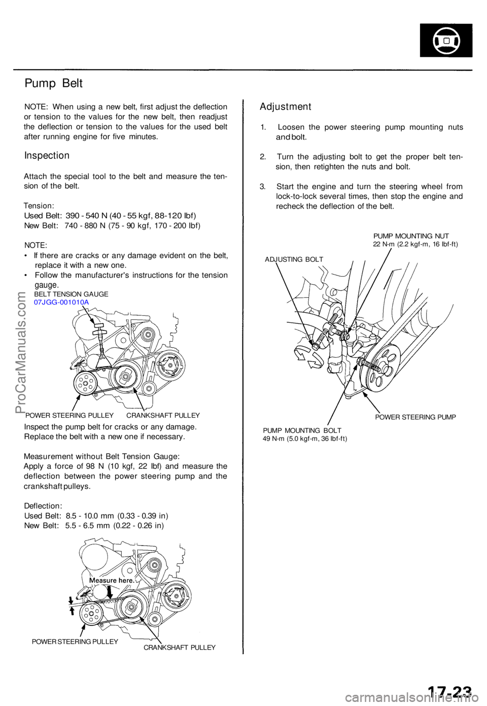
Pump Bel t
NOTE : Whe n usin g a ne w belt , firs t adjus t th e deflectio n
o r tensio n t o th e value s fo r th e ne w belt , the n readjus t
th e deflectio n o r tensio n t o th e value s fo r th e use d bel t
afte r runnin g engin e fo r fiv e minutes .
Inspectio n
Attach th e specia l too l t o th e bel t an d measur e th e ten -
sio n o f th e belt .
Tension :
Used Belt : 39 0 - 54 0 N (4 0 - 5 5 kgf , 88-12 0 Ibf )
New Belt : 74 0 - 88 0 N (7 5 - 9 0 kgf , 17 0 - 20 0 Ibf )
NOTE :
• I f ther e ar e crack s o r an y damag e eviden t o n th e belt ,
replac e it wit h a ne w one .
• Follo w th e manufacturer' s instruction s fo r th e tensio n
gauge.BELT TENSIO N GAUG E07JGG-001010 A
POWER STEERIN G PULLE Y CRANKSHAF T PULLE Y
Inspect th e pum p bel t fo r crack s o r an y damage .
Replac e th e bel t wit h a ne w on e if necessary .
Measuremen t withou t Bel t Tensio n Gauge :
Appl y a forc e o f 9 8 N (1 0 kgf , 2 2 Ibf ) an d measur e th e
deflectio n betwee n th e powe r steerin g pum p an d th e
crankshaf t pulleys .
Deflection :
Use d Belt : 8. 5 - 10. 0 m m (0.3 3 - 0.3 9 in )
Ne w Belt : 5. 5 - 6. 5 m m (0.2 2 - 0.2 6 in )
POWE R STEERIN G PULLE Y
CRANKSHAF T PULLE Y
Adjustmen t
1. Loose n th e powe r steerin g pum p mountin g nut s
and bolt .
2. Tur n th e adjustin g bol t t o ge t th e prope r bel t ten -
sion , the n retighte n th e nut s an d bolt .
3 . Star t th e engin e an d tur n th e steerin g whee l fro m
lock-to-loc k severa l times , the n sto p th e engin e an d
rechec k th e deflectio n o f th e belt .
PUM P MOUNTIN G NU T22 N- m (2. 2 kgf-m , 1 6 Ibf-ft )
ADJUSTIN G BOL T
POWER STEERIN G PUM P
PUM P MOUNTIN G BOL T
4 9 N- m (5. 0 kgf-m , 3 6 Ibf-ft )
ProCarManuals.com
Page 1190 of 1771
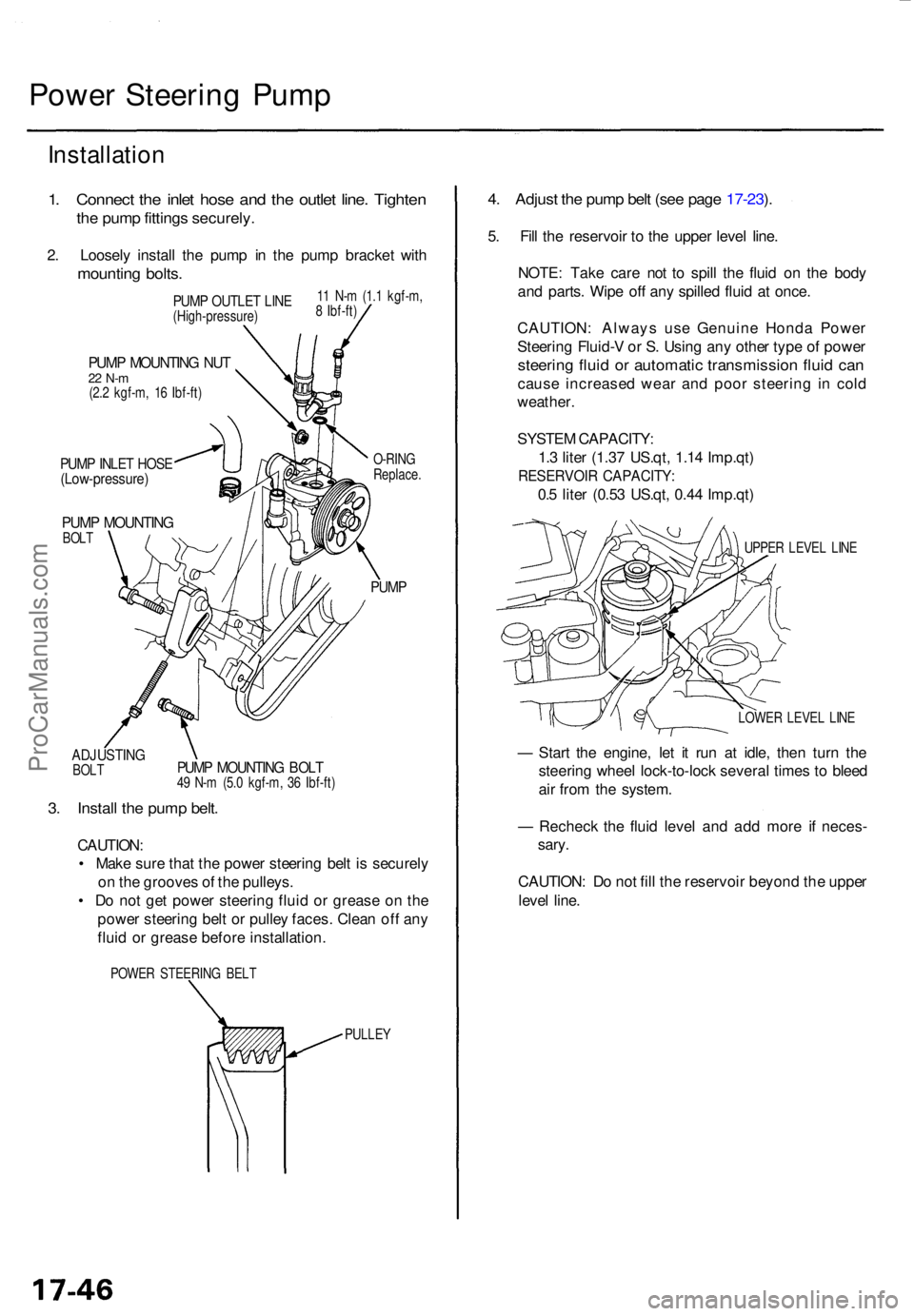
Power Steerin g Pum p
Installatio n
1. Connec t th e inle t hos e an d th e outle t line . Tighte n
the pum p fitting s securely .
2. Loosel y instal l th e pum p i n th e pum p bracke t wit h
mountin g bolts .
ADJUSTIN GBOLT
PUM P MOUNTIN G NU T22 N- m(2.2 kgf-m , 1 6 Ibf-ft )
PUMP INLE T HOS E(Low-pressure )
PUMP MOUNTIN GBOLT O-RIN
G
Replace .
PUMP
PUMP MOUNTIN G BOL T49 N- m (5. 0 kgf-m , 3 6 Ibf-ft )
3. Instal l th e pum p belt .
CAUTION :
• Mak e sur e tha t th e powe r steerin g bel t i s securel y
o n th e groove s o f th e pulleys .
• D o no t ge t powe r steerin g flui d o r greas e o n th e
powe r steerin g bel t o r pulle y faces . Clea n of f an y
flui d o r greas e befor e installation .
POWER STEERIN G BEL T
PULLEY
4. Adjus t th e pum p bel t (se e pag e 17-23 ).
5 . Fil l th e reservoi r t o th e uppe r leve l line .
NOTE : Tak e car e no t t o spil l th e flui d o n th e bod y
an d parts . Wip e of f an y spille d flui d a t once .
CAUTION : Alway s us e Genuin e Hond a Powe r
Steerin g Fluid- V o r S . Usin g an y othe r typ e o f powe r
steerin g flui d o r automati c transmissio n flui d ca n
caus e increase d wea r an d poo r steerin g i n col d
weather .
SYSTE M CAPACITY :
1. 3 lite r (1.3 7 US.qt , 1.1 4 Imp.qt )
RESERVOI R CAPACITY :
0.5 lite r (0.5 3 US.qt , 0.4 4 Imp.qt )
UPPER LEVE L LIN E
LOWE R LEVE L LIN E
— Star t th e engine , le t i t ru n a t idle , the n tur n th e
steerin g whee l lock-to-loc k severa l time s t o blee d
ai r fro m th e system .
— Rechec k th e flui d leve l an d ad d mor e i f neces -
sary .
CAUTION : D o no t fil l th e reservoi r beyon d th e uppe r
leve l line .
PUM P OUTLE T LIN E(High-pressure )1
1 N- m (1. 1 kgf-m ,
8 Ibf-ft )
ProCarManuals.com