Page 523 of 1771

Troubleshooting Precaution s
Kickback
1. Th e moto r operate s whe n th e AB S is functioning , an d flui d i n th e reservoi r i s force d ou t t o th e maste r cylinde r caus -
in g kickbac k a t th e brak e pedal .
Pum p Moto r
1 . Th e pum p moto r operate s whe n th e AB S is functioning .
2 . Th e AB S contro l uni t check s th e pum p moto r operatio n durin g initia l diagnosi s an d vehicl e starts . Yo u ma y hea r th e
fain t operatio n soun d a t thi s time , bu t i t i s normal .
Brak e Flui d Replacement/Ai r Bleedin g
1 . Brak e flui d replacemen t an d ai r bleedin g procedure s ar e th e sam e a s vehicle s withou t ABS . T o cas e bleeding , star t
wit h th e fron t wheels .
Troubleshootin g
1 . Th e troubleshootin g flowchart s procedure s assum e tha t th e caus e o f th e proble m is stil l presen t an d th e AB S indica -
to r ligh t i s stil l on . Followin g th e flowchar t whe n th e AB S indicator light doe s no t com e o n ca n resul t i n incorrec t
judgment.
2. Questio n th e custome r abou t th e condition s whe n th e proble m occurred , an d tr y t o reproduc e th e sam e condition s
fo r troubleshooting .
Fin d ou t whe n th e AB S indicato r ligh t cam e on , suc h a s durin g initia l diagnosis , durin g AB S control , afte r AB S con -
trol , whe n th e vehicl e started , whe n vehicl e spee d wa s a t 1 9 mp h (3 0 km/h) , whe n th e proble m continue d fo r a fe w
second s o r a fe w minutes , etc .
3 . Whe n th e AB S indicato r ligh t doe s no t com e o n durin g th e test-drive , bu t th e troubleshootin g i s performe d base d o n
th e DTC , chec k fo r th e loos e connectors , poo r contac t o f terminals , etc , befor e troubleshooting .
4 . Afte r troubleshooting , eras e th e DT C an d test-driv e th e vehicle . B e sur e tha t th e AB S indicato r ligh t doe s no t com e on .
5 . Th e connecto r illustration s sho w th e femal e connector s wit h a singl e outlin e an d th e mal e connector s wit h a doubl e
outline .
ProCarManuals.com
Page 525 of 1771

Diagnostic Troubl e Cod e (DTC )
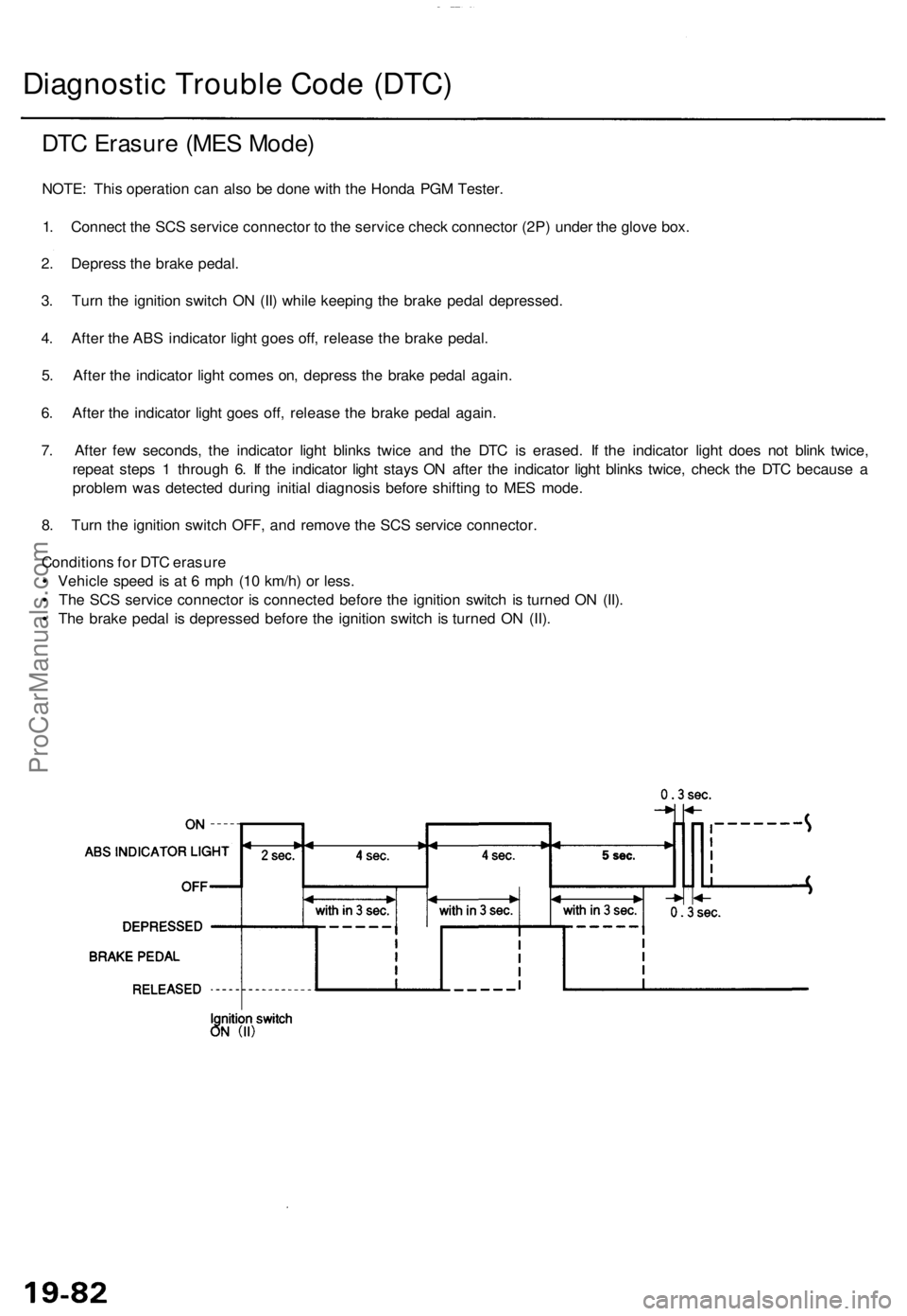
DTC Erasur e (ME S Mode )
NOTE: Thi s operatio n ca n als o b e don e wit h th e Hond a PG M Tester .
1 . Connec t th e SC S servic e connecto r t o th e servic e chec k connecto r (2P ) unde r th e glov e box .
2 . Depres s th e brak e pedal .
3 . Tur n th e ignitio n switc h O N (II ) whil e keepin g th e brak e peda l depressed .
4 . Afte r th e AB S indicator light goe s off , releas e th e brak e pedal .
5 . Afte r th e indicato r ligh t come s on , depres s th e brak e peda l again .
6 . Afte r th e indicato r ligh t goe s off , releas e th e brak e peda l again .
7 . Afte r fe w seconds , th e indicato r ligh t blink s twic e an d th e DT C is erased . I f th e indicato r ligh t doe s no t blin k twice ,
repea t step s 1 throug h 6 . I f th e indicato r ligh t stay s O N afte r th e indicato r ligh t blink s twice , chec k th e DT C becaus e a
proble m wa s detecte d durin g initia l diagnosi s befor e shiftin g t o ME S mode .
8 . Tur n th e ignitio n switc h OFF , an d remov e th e SC S servic e connector .
Condition s fo r DT C erasur e
• Vehicl e spee d i s a t 6 mp h (1 0 km/h ) o r less .
• Th e SC S servic e connecto r i s connecte d befor e th e ignitio n switc h i s turne d O N (II) .
• Th e brak e peda l i s depresse d befor e th e ignitio n switc h i s turne d O N (II) .
ProCarManuals.com
Page 528 of 1771
Component Location s
ABS CONTRO L UNI TSERVIC E CHEC K CONNECTO R (2P )
STEERIN G ANGL E SENSO R RIGHT-REA
R WHEE L SENSO R
TCS CONTRO L UNI T
UNDER-DAS H RELA Y BO X
POWERTRAI N
CONTRO L MODUL E (PCM )
EC T SENSO R
TC S CONTRO L VALV E
SENSO R
RIGHT-FRON T
WHEE L SENSO R
LEFT-REA RWHEEL SENSO R
TC S SWITC H
UNDER-DAS H FUSE/RELA Y BO X
UNDER-DAS H FUSE/RELA Y BO X
GAUG E ASSEMBL Y
TC S INDICATO R LIGH T
UNDER-HOO D FUSE/RELA Y BO X BACK-U
P LIGHTS /
METE R LIGHT S
(1 0 A ) FUS E EC
U (PCM)/CRUIS E
CONTRO L
(1 5 A ) FUS E
BATTER Y (120A ) FUS E
UNDER-DASH RELA Y BO X
I G S W (5 0 A ) FUS E
FAIL-SAF E RELA Y
TCS CONTRO L
VALV E ACTUATO R
UNDER-HOO D FUSE/RELA Y BO X
LEFT-FRON
T WHEE L SENSO R
TCS/RUNNIN GLIGHT (1 5 A ) FUS ESTOP/HOR N(20 A ) FUS E
ProCarManuals.com
Page 536 of 1771

Diagnostic Troubl e Cod e (DTC )
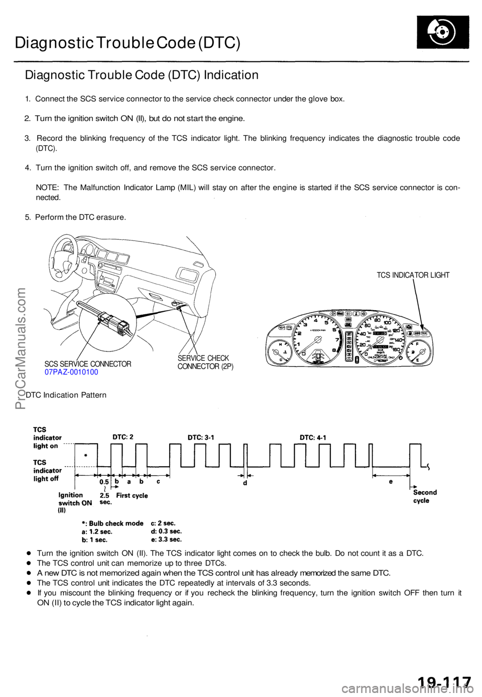
Diagnosti c Troubl e Cod e (DTC ) Indicatio n
1. Connec t th e SC S servic e connecto r t o th e servic e chec k connecto r unde r th e glov e box .
2. Tur n th e ignitio n switc h O N (II) , bu t d o no t star t th e engine .
3. Recor d th e blinkin g frequenc y o f th e TC S indicato r light . Th e blinkin g frequenc y indicate s th e diagnosti c troubl e cod e
(DTC) .
4. Tur n th e ignitio n switc h off , an d remov e th e SC S servic e connector .
NOTE : Th e Malfunctio n Indicato r Lam p (MIL ) wil l sta y o n afte r th e engin e is starte d i f th e SC S servic e connecto r i s con -
nected .
5 . Perfor m th e DT C erasure .
SCS SERVIC E CONNECTO R07PAZ-001010 0
TCS INDICATO R LIGH T
SERVIC E CHEC KCONNECTO R (2P )
DTC Indicatio n Patter n
Tur n th e ignitio n switc h O N (II) . Th e TC S indicato r ligh t come s o n t o chec k th e bulb . D o no t coun t i t a s a DTC .
Th e TC S contro l uni t ca n memoriz e u p to thre e DTCs .
A ne w DT C is no t memorize d agai n whe n th e TC S contro l uni t ha s alread y memorize d th e sam e DTC .
The TC S contro l uni t indicate s th e DT C repeatedl y a t interval s o f 3. 3 seconds .
I f yo u miscoun t th e blinkin g frequenc y o r i f yo u rechec k th e blinkin g frequency , tur n th e ignitio n switc h OF F the n tur n i t
O N (II ) t o cycl e th e TC S indicato r ligh t again .
ProCarManuals.com
Page 537 of 1771
Diagnostic Trouble Code (DTC)
DTC Erasure
1. Pull the parking brake lever up.
2. Push and hold the TCS switch, then turn the ignition switch ON (II).
3. Hold the TCS switch pushed for four seconds (do not release the TCS switch), then release the TCS switch for less than
six seconds.
4. After three seconds, the TCS indicator light go off three times, then turn it on. It means that the DTC is erased.
NOTE:
• Follow these steps exactly. If you connect the SCS service connector and/or release the parking brake lever during
these steps, the DTC will not be erased.
• If the TCS indicator light blinks repeatedly, replace the TCS control unit.
Standard Indication Pattern
Abnormal Indication PatternProCarManuals.com
Page 542 of 1771
Center Console
Replacement
CAUTION: When prying with a flat tip screwdriver, wrap
it with protective tape to prevent damage.
NOTE: Take care not to scratch the center console, front
seat and related parts.
1. Slide the front seats backward fully.
2. Remove the A/T gear position indicator trim, and
disconnect the indicator light.
3. Open the armrest, then remove the inner mat and
remove the ashtray.
4. Remove the screws, then remove the center con-
sole. Disconnect the cigarette lighter connector,
front fog light switch connector and seat heater
switch connectors.
5. Installation is the reverse of the removal procedure.
NOTE:
• Make sure the wire harnesses are not pinched.
• Make sure the connectors are connected properly.ProCarManuals.com
Page 547 of 1771
Front Bumper
Replacement
CAUTION: Wear gloves to remove and install the front
bumper.
NOTE:
An assistant is helpful when removing the front
bumper.
Take care not to scratch the front bumper and body.
Open the hood.
1. Remove the bolts and screw from each side.
FRONT BUMPER
INNER FENDER
2. Remove the clips. Remove the front bumper, then
disconnect the connectors.
FRONT SIDE
MARKER LIGHT
CONNECTOR
FRONT SIDE
MARKER LIGHT
CONNECTOR
B
FRONT TURN
SIGNAL LIGHT
CONNECTOR
FRONT TURN
SIGNAL LIGHT
CONNECTORS
3. Remove the absorber and front bumper lower spoiler
from the front bumper.
FRONT BUMPER
ABSORBER
FRONT BUMPER
LOWER SPOILER
4. Remove the front bulkhead cover.
NOTE: After pulling the inner clips out, remove the
front bulkhead cover with the clips.
FRONT BULKHEAD
COVER
CLIP
FRONT BULKHEAD
COVER
FRONT BUMPER
INNER
CLIPProCarManuals.com
Page 548 of 1771
5. Remove the front bumper beam.
FRONT
BUMPER
BEAM
FRONT AIR
GUIDE PLATE
CLIP
6. Installation is the reverse of the removal procedure.
NOTE:
When installing the front bumper beam, align it
with both alignment marks on the body, then
tighten the bolts.
Align the front bumper with the front fender and
headlight properly.
HOOKS
FRONT
BUMPER
BEAM
BOLT
ALIGNMENT
MARK
(Beam side)
FRONT
BUMPER
FRONT
BUMPER
BEAM
ALIGNMENT
MARK
(Body side)
SIDE
CLIP
BOLTSProCarManuals.com