1995 ACURA TL light
[x] Cancel search: lightPage 926 of 1771
Intake Ai r Syste m Emissio
n Contro l Syste m
Intake Ai r Bypas s (IAB ) Contro l
Syste m (cont'd )
Intake Ai r Bypas s (IAB ) Contro l Valv e Testin g
1. Chec k th e IA B contro l valv e shaf t fo r bindin g o r stick -
ing.
2. Chec k th e IA B contro l valv e fo r smoot h movement .
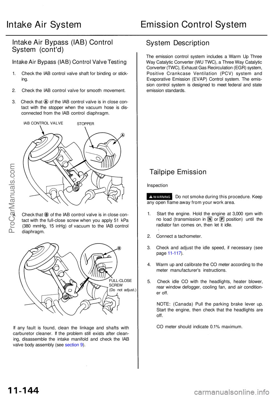
3. Chec k tha t o f th e IA B contro l valv e is i n clos e con -
tac t wit h th e stoppe r whe n th e vacuu m hos e i s dis -
connecte d fro m th e IA B contro l diaphragm .
IAB CONTRO L VALV ESTOPPE R
4.Chec k tha t o f th e IA B contro l valv e is in clos e con -
tac t wit h th e full-clos e scre w whe n yo u appl y 5 1 kP a
(38 0 mmHg , 1 5 inHg ) o f vacuu m to th e IA B contro l
diaphragm .
FULL-CLOS ESCREW(Do no t adjust. )
If an y faul t i s found , clea n th e linkag e an d shaft s wit h
carbureto r cleaner . I f th e proble m stil l exist s afte r clean -
ing , disassembl e th e intak e manifol d an d chec k th e IA B
valv e bod y assembl y (se e sectio n 9 ).
Syste m Descriptio n
The emissio n contro l syste m include s a War m U p Thre e
Wa y Catalyti c Converte r (W U TWC) , a Thre e Wa y Catalyti c
Converte r (TWC) , Exhaus t Ga s Recirculatio n (EGR ) system ,
Positiv e Crankcas e Ventilatio n (PCV ) syste m an d
Evaporativ e Emissio n (EVAP ) Contro l system . Th e emis -
sio n contro l syste m is designe d t o mee t federa l an d stat e
emissio n standards .
Tailpipe Emissio n
Inspectio n
Do no t smok e durin g thi s procedure . Kee p
an y ope n flam e awa y fro m you r wor k area .
1 . Star t th e engine . Hol d th e engin e a t 3,00 0 rp m wit h
no loa d (transmissio n i n o r position ) unti l th e
radiato r fa n come s on , the n le t i t idle .
2 . Connec t a tachometer .
3 . Chec k an d adjus t th e idl e speed , i f necessar y (se e
pag e 11-117 ).
4 . War m u p an d calibrat e th e C O mete r accordin g to th e
mete r manufacturer' s instructions .
5 . Chec k idl e C O wit h th e headlights , heate r blower ,
rea r windo w defogger , coolin g fan , an d ai r condition -
er off .
NOTE : (Canada ) Pul l th e parkin g brak e leve r up .
Star t th e engine , the n chec k tha t th e headlight s ar e
off.
CO mete r shoul d indicat e 0.1 % maximum .
ProCarManuals.com
Page 929 of 1771
Positive Crankcase Ventilation (PCV) System
Description
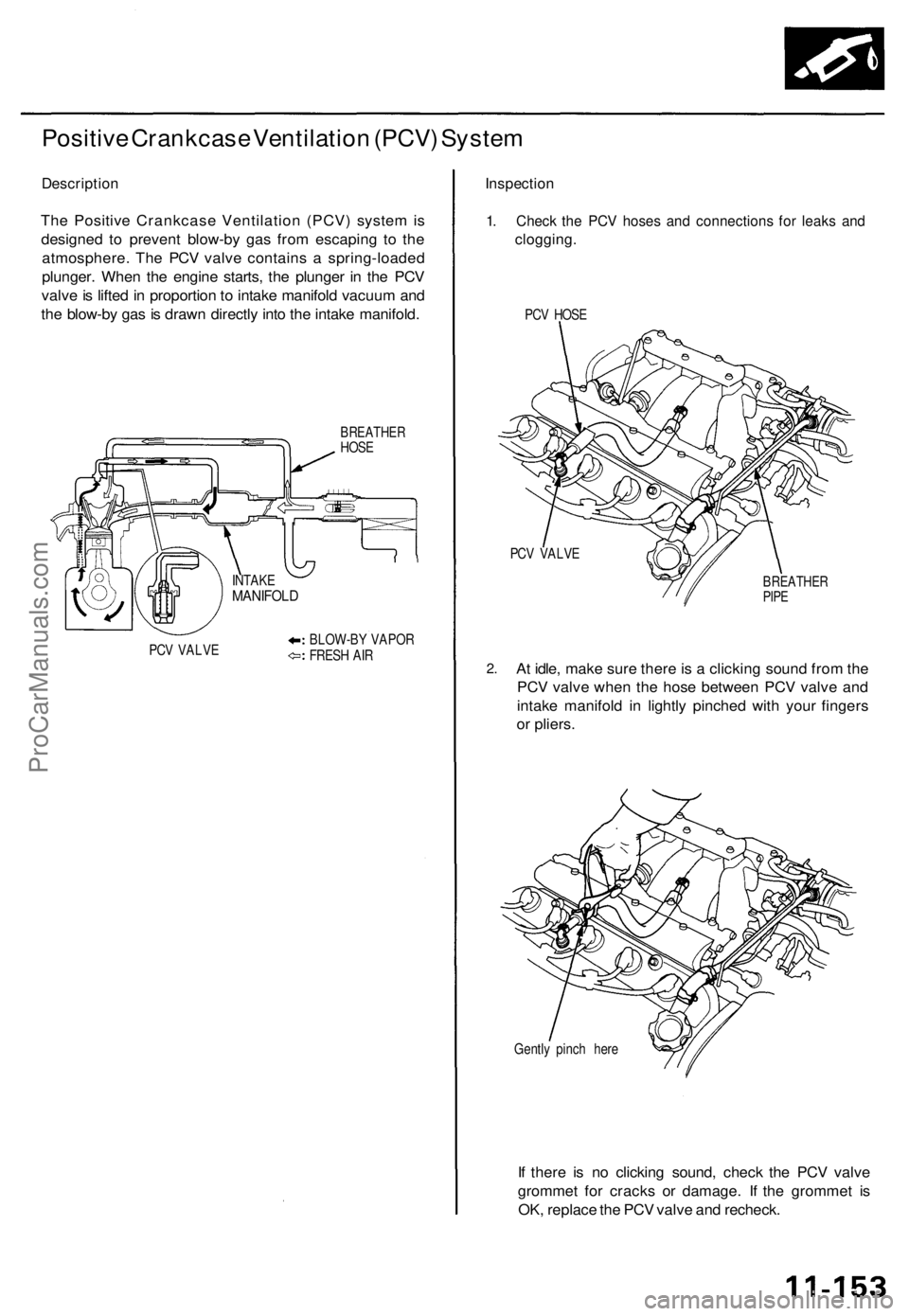
The Positive Crankcase Ventilation (PCV) system is
designed to prevent blow-by gas from escaping to the
atmosphere. The PCV valve contains a spring-loaded
plunger. When the engine starts, the plunger in the PCV
valve is lifted in proportion to intake manifold vacuum and
the blow-by gas is drawn directly into the intake manifold.
BREATHER
HOSE
PCV VALVE
BLOW-BY VAPOR
FRESH AIR
Inspection
1. Check the PCV hoses and connections for leaks and
clogging.
PCV HOSE
PCV VALVE
2.
BREATHER
PIPE
At idle, make sure there is a clicking sound from the
PCV valve when the hose between PCV valve and
intake manifold in lightly pinched with your fingers
or pliers.
Gently pinch here
If there is no clicking sound, check the PCV valve
grommet for cracks or damage. If the grommet is
OK, replace the PCV valve and recheck.
INTAKE
MANIFOLDProCarManuals.com
Page 951 of 1771
Description
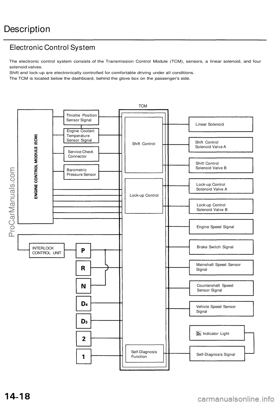
The electronic control system consists of the Transmission Control Module (TCM), sensors, a linear solenoid, and four
solenoid valves.
Shift and lock-up are electronically controlled for comfortable driving under all conditions.
The TCM is located below the dashboard, behind the glove box on the passenger's side.
TCM
Linear Solenoid
Shift Control
Solenoid Valve A
Shift Control
Solenoid Valve B
Lock-up Control
Solenoid Valve A
Lock-up Control
Solenoid Valve B
Engine Speed Signal
Brake Switch Signal
Mainshaft Speed Sensor
Signal
Countershaft Speed
Sensor Signal
Vehicle Speed Sensor
Signal
Indicator Light
Self-Diagnosis Signal
Electronic Control System
Shift Control
Lock-up Control
Throttle Position
Sensor Signal
Engine Coolant
Temperature
Sensor Signal
Service Check
Connector
Barometric
Pressure Sensor
INTERLOCK
CONTROL UNIT
Self-Diagnosis
FunctionProCarManuals.com
Page 971 of 1771
Description
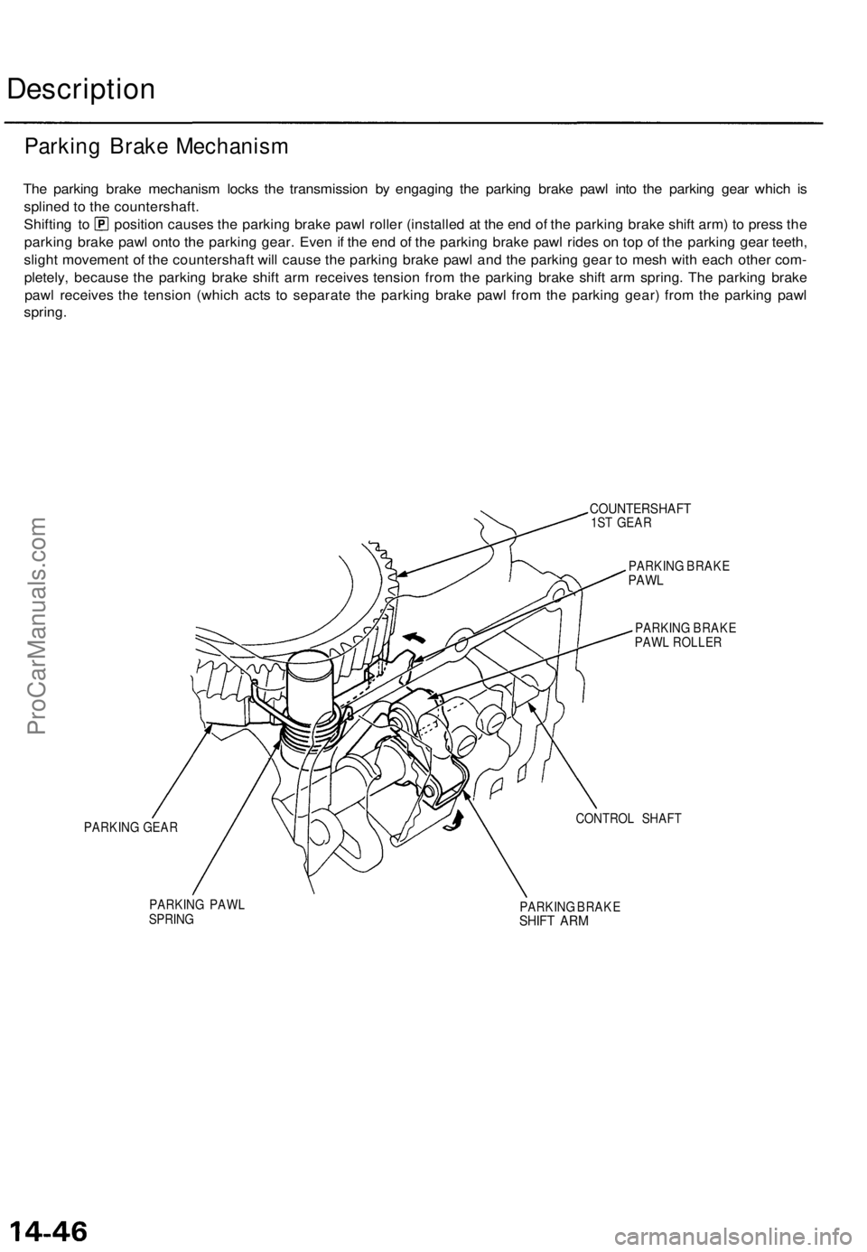
The parking brake mechanism locks the transmission by engaging the parking brake pawl into the parking gear which is
splined to the countershaft.
Shifting to position causes the parking brake pawl roller (installed at the end of the parking brake shift arm) to press the
parking brake pawl onto the parking gear. Even if the end of the parking brake pawl rides on top of the parking gear teeth,
slight movement of the countershaft will cause the parking brake pawl and the parking gear to mesh with each other com-
pletely, because the parking brake shift arm receives tension from the parking brake shift arm spring. The parking brake
pawl receives the tension (which acts to separate the parking brake pawl from the parking gear) from the parking pawl
spring.
PARKING GEAR
COUNTERSHAFT
1ST GEAR
PARKING BRAKE
PAWL
PARKING BRAKE
PAWL ROLLER
CONTROL SHAFT
PARKING PAWL
SPRING
PARKING BRAKE
SHIFT ARM
Parking Brake MechanismProCarManuals.com
Page 975 of 1771

Troubleshooting Procedures
Checking the Diagnostic Trouble Code (DTC)
with an OBD II Scan tool or Honda PGM Tester
When the TCM senses an abnormality in the input or output systems, the indicator light in the gauge assembly will
blink. When the 16P Data Link Connector (DLC) (located behind the ashtray) is connected to the OBD II Scan Tool or Honda
PGM Tester as shown, the scan tool or tester will indicate the Diagnostic Trouble Code (DTC) when the ignition switch is
turned ON(II).
When the indicator light has been reported on, connect the OBD II Scan Tool conforming to SAE J1978 or Honda PGM
Tester to the DLC (16P) behind the ashtray. Turn the ignition switch on (II), and observe the DTC on the screen of the OBD II
Scan Tool or Honda PGM Tester. After determining the DTC, refer to the electrical system Symptom-to-Component Chart
on page 14-56 and 14-57.
NOTE: See the OBD II Scan Tool or Honda PGM Tester user's manual for specific instruction.
OBD II SCAN TOOL or
HONDA PGM TESTER
Some PGM-FI problems will also make the indicator light come on. After repairing the PGM-FI system, disconnect the
BACK UP RADIO fuse (10 A) in the under-hood fuse/relay box for more than 10 seconds to reset the TCM memory, then
retest.
NOTE: Disconnecting the BACK UP RADIO fuse also cancels the radio anti-theft code, preset stations and the clock setting.
Get the customer's code number, and make note of the radio presets before removing the fuse so you can reset them.
DATA LINK CONNECTOR (16P)ProCarManuals.com
Page 976 of 1771
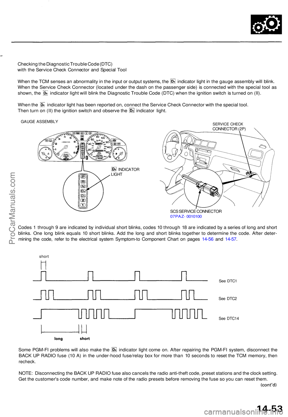
Checking th e Diagnosti c Troubl e Cod e (DTC )
wit h th e Servic e Chec k Connecto r an d Specia l Too l
Whe n th e TC M sense s a n abnormalit y in th e inpu t o r outpu t systems , th e indicato r ligh t i n th e gaug e assembl y wil l blink .
Whe n th e Servic e Chec k Connecto r (locate d unde r th e das h o n th e passenge r side ) i s connecte d wit h th e specia l too l a s
shown , th e indicato r ligh t wil l blin k th e Diagnosti c Troubl e Cod e (DTC ) whe n th e ignitio n switc h is turne d o n (II) .
Whe n th e indicato r ligh t ha s bee n reporte d on , connec t th e Servic e Chec k Connecto r wit h th e specia l tool .
Then tur n o n (II ) th e ignitio n switc h an d observ e th e indicato r light .
GAUG E ASSEMBL YSERVICE CHEC KCONNECTO R (2P )
INDICATO RLIGHT
SCS SERVIC E CONNECTO R07PAZ- 001010 0
Codes 1 throug h 9 ar e indicate d b y individua l shor t blinks , code s 1 0 throug h 1 8 ar e indicate d b y a serie s o f lon g an d shor t
blinks . On e lon g blin k equal s 1 0 shor t blinks . Ad d th e lon g an d shor t blink s togethe r t o determin e th e code . Afte r deter -
minin g th e code , refe r t o th e electrica l syste m Symptom-t o Componen t Char t o n page s 14-5 6 an d 14-57 .
short
Some PGM-F I problem s wil l als o mak e th e indicato r ligh t com e on . Afte r repairin g th e PGM-F I system , disconnec t th e
BAC K U P RADI O fus e (1 0 A ) i n th e under-hoo d fuse/rela y bo x fo r mor e tha n 1 0 second s t o rese t th e TC M memory , the n
recheck .
NOTE: Disconnectin g th e BAC K U P RADI O fus e als o cancel s th e radi o anti-theft code, prese t station s an d th e cloc k setting .
Ge t th e customer' s cod e number , an d mak e not e o f th e radi o preset s befor e removin g th e fus e s o yo u ca n rese t them .
See DTC 1
See DTC 2
See DTC1 4
ProCarManuals.com
Page 979 of 1771
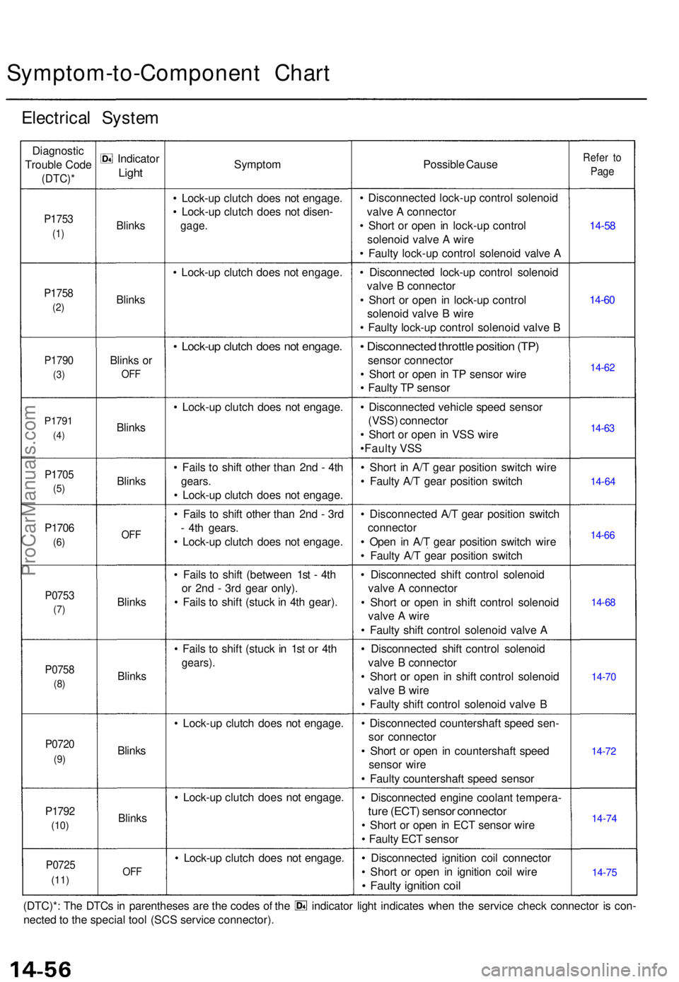
Symptom-to-Component Char t
Electrica l Syste m
Diagnosti c
Troubl e Cod e
(DTC) *
P1753
(1)
P175 8
(2)
P179 0
(3)
P179 1
(4)
P170 5
(5)
P170 6
(6)
P075 3
(7)
P075 8
(8)
P072 0
(9)
P179 2
(10)
P072 5
(11)
Indicato r
Light
Blink s
Blink s
Blinks o r
OF F
Blink s
Blink s
OFF
Blink s
Blink s
Blinks
Blink s
OFF
Sympto m
• Lock-u p clutc h doe s no t engage .
• Lock-u p clutc h doe s no t disen -
gage.
• Lock-u p clutc h doe s no t engage .
• Lock-u p clutc h doe s no t engage .
• Lock-u p clutc h doe s no t engage .
• Fail s t o shif t othe r tha n 2n d - 4t h
gears .
• Lock-u p clutc h doe s no t engage .
• Fail s t o shif t othe r tha n 2n d - 3r d
- 4t h gears .
• Lock-u p clutc h doe s no t engage .
• Fail s t o shif t (betwee n 1s t - 4t h
o r 2n d - 3r d gea r only) .
• Fail s t o shif t (stuc k in 4t h gear) .
• Fail s t o shif t (stuc k i n 1s t o r 4t h
gears) .
• Lock-u p clutc h doe s no t engage .
• Lock-u p clutc h doe s no t engage .
• Lock-u p clutc h doe s no t engage . Possibl
e Caus e
• Disconnecte d lock-u p contro l solenoi d
valv e A connecto r
• Shor t o r ope n i n lock-u p contro l
solenoi d valv e A wir e
• Fault y lock-u p contro l solenoi d valv e A
• Disconnecte d lock-u p contro l solenoi d
valv e B connecto r
• Shor t o r ope n i n lock-u p contro l
solenoi d valv e B wir e
• Fault y lock-u p contro l solenoi d valv e B
• Disconnecte d throttl e positio n (TP )
senso r connecto r
• Shor t o r ope n in T P senso r wir e
• Fault y T P senso r
• Disconnecte d vehicl e spee d senso r
(VSS ) connecto r
• Shor t o r ope n i n VS S wir e
•Fault y VS S
• Shor t i n A/ T gea r positio n switc h wir e
• Fault y A/ T gea r positio n switc h
• Disconnecte d A/ T gea r positio n switc h
connecto r
• Ope n i n A/ T gea r positio n switc h wir e
• Fault y A/ T gea r positio n switc h
• Disconnecte d shif t contro l solenoi d
valv e A connecto r
• Shor t o r ope n i n shif t contro l solenoi d
valv e A wir e
• Fault y shif t contro l solenoi d valv e A
• Disconnecte d shif t contro l solenoi d
valv e B connecto r
• Shor t o r ope n i n shif t contro l solenoi d
valv e B wir e
• Fault y shif t contro l solenoi d valv e B
• Disconnecte d countershaf t spee d sen -
so r connecto r
• Shor t o r ope n i n countershaf t spee d
senso r wir e
• Fault y countershaf t spee d senso r
• Disconnecte d engin e coolan t tempera -
ture (ECT ) senso r connecto r
• Shor t o r ope n in EC T senso r wir e
• Fault y EC T senso r
• Disconnecte d ignitio n coi l connecto r
• Shor t o r ope n i n ignitio n coi l wir e
• Fault y ignitio n coi l
Refe r t o
Pag e
14-5 8
14-6 0
14-6 2
14-6 3
14-6 4
14-6 6
14-6 8
14-7 0
14-7 2
14-7 4
14-7 5
(DTC)* : Th e DTC s i n parenthese s ar e th e code s o f th e indicato r ligh t indicate s whe n th e servic e chec k connecto r i s con -
necte d to th e specia l too l (SC S servic e connector) .
ProCarManuals.com
Page 980 of 1771
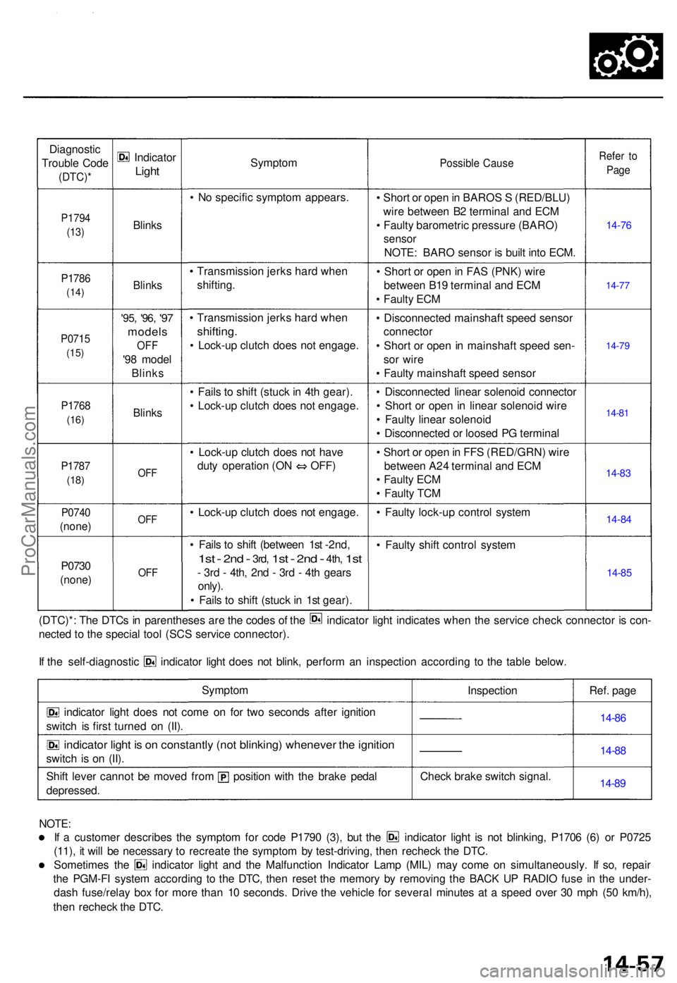
Diagnostic
Troubl e Cod e
(DTC) *
P1794
(13)
P178 6
(14)
P071 5
(15)
P176 8
(16)
P178 7
(18)
P074 0
(none )
P0730
(none )
Indicato r
Light
Blink s
Blinks
'95, '96 , '97
model s
OFF
'98 mode l
Blink s
Blinks
OFF
OF F
OFF
Sympto m
• N o specifi c sympto m appears .
• Transmissio n jerk s har d whe n
shifting .
• Transmissio n jerk s har d whe n
shifting .
• Lock-u p clutc h doe s no t engage .
• Fail s t o shif t (stuc k in 4t h gear) .
• Lock-u p clutc h doe s no t engage .
• Lock-u p clutc h doe s no t hav e
duty operatio n (O N OFF )
• Lock-u p clutc h doe s no t engage .
• Fail s t o shif t (betwee n 1s t -2nd,
1s t - 2n d - 3rd , 1st - 2nd - 4th , 1st
- 3r d - 4th , 2n d - 3r d - 4t h gear s
only) .
• Fail s t o shif t (stuc k in 1s t gear) .
Possibl e Caus e
• Shor t o r ope n in BARO S S (RED/BLU )
wir e betwee n B 2 termina l an d EC M
• Fault y barometri c pressur e (BARO )
sensor
NOTE : BAR O senso r i s buil t int o ECM .
• Shor t o r ope n in FA S (PNK ) wir e
betwee n B1 9 termina l an d EC M
• Fault y EC M
• Disconnecte d mainshaf t spee d senso r
connecto r
• Shor t o r ope n in mainshaf t spee d sen -
so r wir e
• Fault y mainshaf t spee d senso r
• Disconnecte d linea r solenoi d connecto r
• Shor t o r ope n in linea r solenoi d wir e
• Fault y linea r solenoi d
• Disconnecte d o r loose d P G termina l
• Shor t o r ope n in FF S (RED/GRN ) wir e
betwee n A2 4 termina l an d EC M
• Fault y EC M
• Fault y TC M
• Fault y lock-u p contro l syste m
• Fault y shif t contro l syste m
Refer t o
Pag e
14-7 6
14-77
14-7 9
14-8 1
14-8 3
14-8 4
14-8 5
(DTC)* : Th e DTC s i n parenthese s ar e th e code s o f th e indicato r ligh t indicate s whe n th e servic e chec k connecto r i s con -
necte d t o th e specia l too l (SC S servic e connector) .
If th e self-diagnosti c indicato r ligh t doe s no t blink , perfor m a n inspectio n accordin g t o th e tabl e below .
Sympto m
indicator ligh t doe s no t com e o n fo r tw o second s afte r ignitio n
switc h i s firs t turne d o n (II) .
indicato r ligh t i s o n constantl y (no t blinking ) wheneve r th e ignitio n
switch i s o n (II) .
Shif t leve r canno t b e move d fro m positio n wit h th e brak e peda l
depressed . Inspectio
n
Chec k brak e switc h signal . Ref
. pag e
14-86
14-8 8
14-8 9
NOTE :
If a custome r describe s th e sympto m fo r cod e P179 0 (3) , bu t th e indicato r ligh t i s no t blinking , P170 6 (6 ) o r P072 5
(11) , i t wil l b e necessar y t o recreat e th e sympto m b y test-driving , the n rechec k th e DTC .
Sometime s th e indicato r ligh t an d th e Malfunctio n Indicato r Lam p (MIL ) ma y com e o n simultaneously . I f so , repai r
th e PGM-F I syste m accordin g t o th e DTC , the n rese t th e memor y b y removin g th e BAC K U P RADI O fus e i n th e under -
das h fuse/rela y bo x fo r mor e tha n 1 0 seconds . Driv e th e vehicl e fo r severa l minute s a t a spee d ove r 3 0 mp h (5 0 km/h) ,
the n rechec k th e DTC .
ProCarManuals.com