1995 ACURA TL light
[x] Cancel search: lightPage 299 of 1771
Description
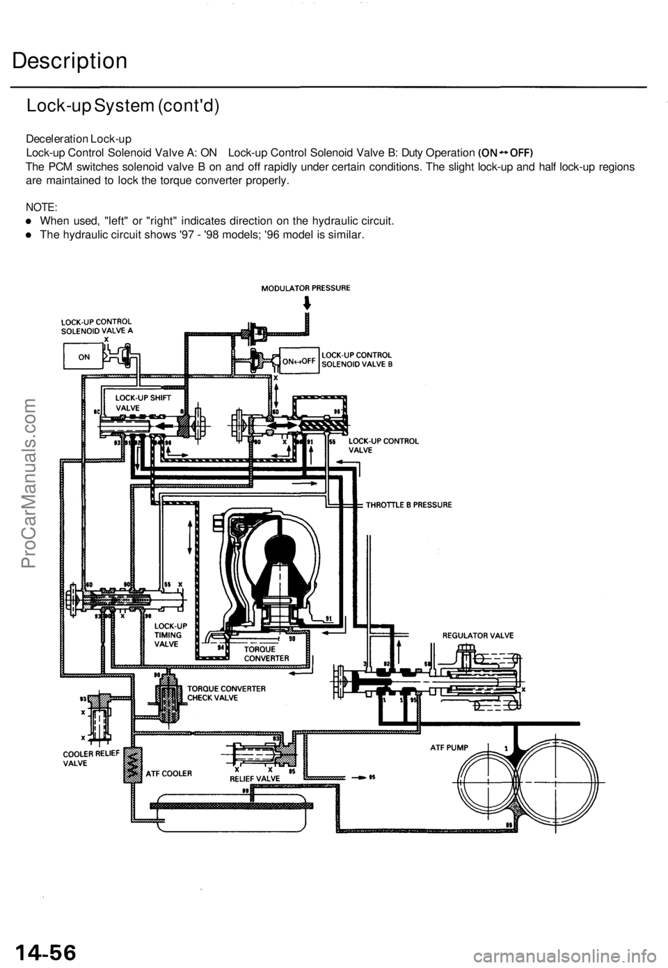
Lock-up System (cont'd)
Deceleration Lock-up
Lock-up Control Solenoid Valve A: ON Lock-up Control Solenoid Valve B: Duty Operation
The PCM switches solenoid valve B on and off rapidly under certain conditions. The slight lock-up and half lock-up regions
are maintained to lock the torque converter properly.
NOTE:
When used, "left" or "right" indicates direction on the hydraulic circuit.
The hydraulic circuit shows '97 - '98 models; '96 model is similar.ProCarManuals.com
Page 305 of 1771

Troubleshooting Procedure s
Checking th e Diagnosti c Troubl e Cod e (DTC )
wit h a n OB D II Sca n too l o r Hond a PG M Teste r
When th e PC M sense s a n abnormalit y i n th e inpu t o r outpu t systems , th e indicato r ligh t i n th e gaug e assembl y wil l
blink . Whe n th e 16 P Dat a Lin k Connecto r (DLC ) (locate d behin d th e ashtray ) i s connecte d to th e OB D II Sca n Too l o r Hond a
PG M Teste r a s shown , th e sca n too l o r teste r wil l indicat e th e Diagnosti c Troubl e Cod e (DTC ) whe n th e ignitio n switc h i s
turne d O N (II) .
Whe n th e indicato r ligh t ha s bee n reporte d on , connec t th e OB D II Sca n Too l conformin g t o SA E J197 8 o r Hond a PG M
Teste r t o th e DL C (16P ) behin d th e ashtray . Tur n th e ignitio n switc h o n (II) , an d observ e th e DT C o n th e scree n o f th e OB D II
Sca n Too l o r Hond a PG M Tester . Afte r determinin g th e DTC , refe r t o th e electrica l syste m Symptom-to-Componen t Char t
o n pag e 14-6 8 an d 14-69 .
NOTE : Se e th e OB D II Sca n Too l o r Hond a PG M Teste r user' s manua l fo r specifi c instructions .
DATA LIN K CONNECTO R (16P )
OBD II SCA N TOO L o r
HOND A PG M TESTE R
Some PGM-F I problem s wil l als o mak e th e indicator light com e on . Afte r repairin g th e PGM-F I system , disconnec t th e
BAC K UP , RADI O fus e (1 0 A ) i n th e under-hoo d fuse/rela y bo x fo r mor e tha n 1 0 second s t o rese t th e PC M memory , the n
retest .
NOTE : Disconnectin g th e BAC K UP , RADI O fus e als o cancel s th e radi o anti-thef t code , prese t station s an d th e cloc k setting .
Ge t th e customer' s cod e number , an d mak e not e o f th e radi o preset s befor e removin g th e fus e s o yo u ca n rese t them .
ProCarManuals.com
Page 306 of 1771
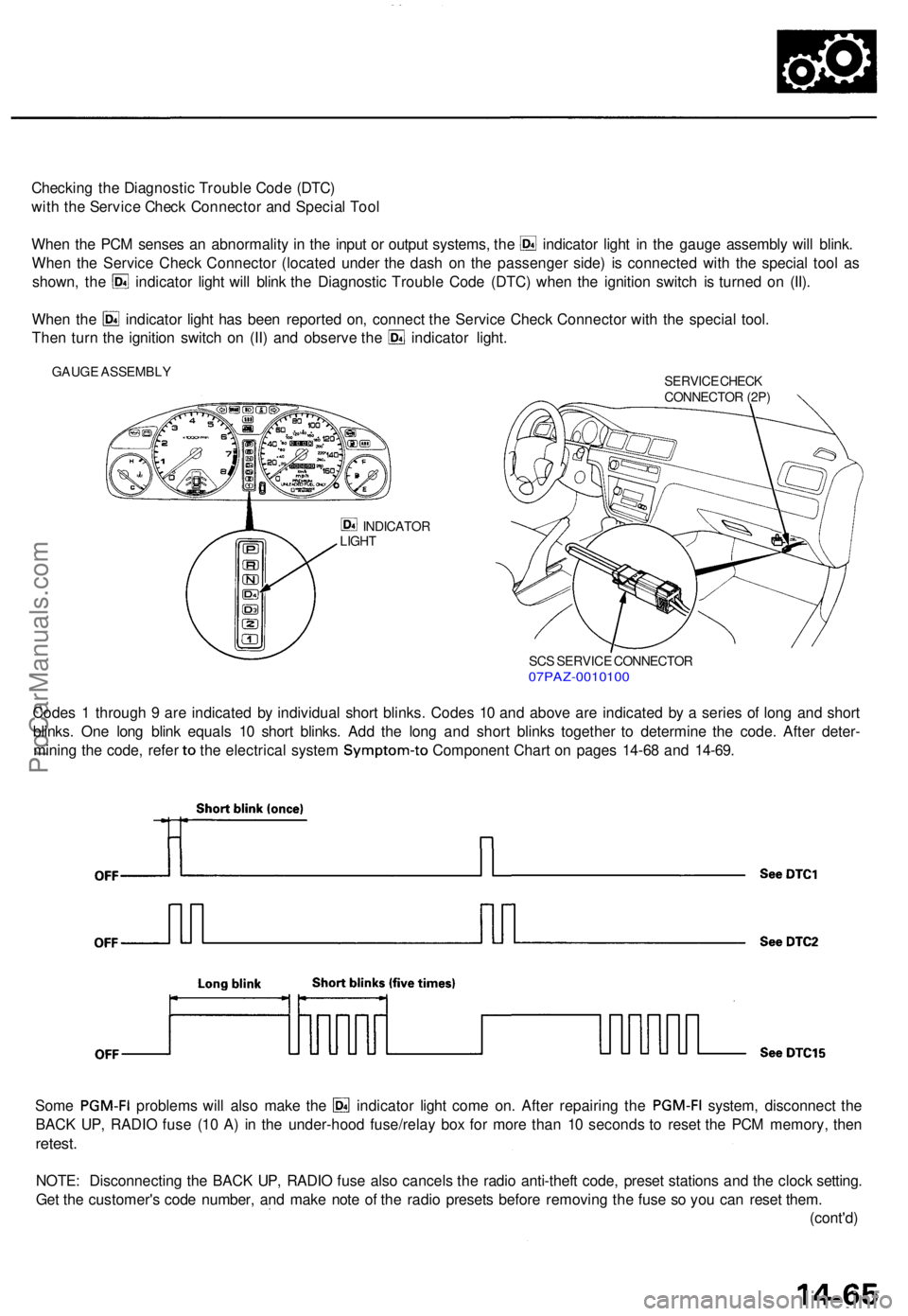
Checking th e Diagnosti c Troubl e Cod e (DTC )
wit h th e Servic e Chec k Connecto r an d Specia l Too l
Whe n th e PC M sense s a n abnormalit y i n th e inpu t o r outpu t systems , th e indicato r ligh t i n th e gaug e assembl y wil l blink .
Whe n th e Servic e Chec k Connecto r (locate d unde r th e das h o n th e passenge r side ) i s connecte d wit h th e specia l too l a s
shown , th e indicato r ligh t wil l blin k th e Diagnosti c Troubl e Cod e (DTC ) whe n th e ignitio n switc h i s turne d o n (II) .
Whe n th e indicato r ligh t ha s bee n reporte d on , connec t th e Servic e Chec k Connecto r wit h th e specia l tool .
Then tur n th e ignitio n switc h o n (II ) an d observ e th e indicato r light .
GAUG E ASSEMBL Y
SERVICE CHEC K
CONNECTO R (2P )
INDICATO R
LIGH T
SCS SERVIC E CONNECTO R07PAZ-001010 0
Codes 1 throug h 9 ar e indicate d b y individua l shor t blinks . Code s 1 0 an d abov e ar e indicate d b y a serie s o f lon g an d shor t
blinks . On e lon g blin k equal s 1 0 shor t blinks . Ad d th e lon g an d shor t blink s togethe r t o determin e th e code . Afte r deter -
mining th e code , refe r to th e electrica l syste m Symptom-t o Component Char t o n page s 14-6 8 an d 14-69 .
Some PGM-F I problem s wil l als o mak e th e indicato r ligh t com e on . Afte r repairin g th e PGM-F I system, disconnec t th e
BAC K UP , RADI O fus e (1 0 A ) i n th e under-hoo d fuse/rela y bo x fo r mor e tha n 1 0 second s t o rese t th e PC M memory , the n
retest .
NOTE : Disconnectin g th e BAC K UP , RADI O fus e als o cancel s th e radi o anti-thef t code , prese t station s an d th e cloc k setting .
Ge t th e customer' s cod e number , an d mak e not e o f th e radi o preset s befor e removin g th e fus e s o yo u ca n rese t them .
(cont'd )
ProCarManuals.com
Page 309 of 1771
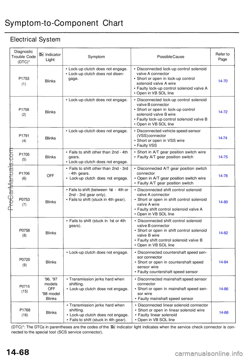
Symptom-to-Component Char t
Electrica l Syste m
Diagnosti c
Troubl e Cod e
(DTC) *
P1753
(1)
P175 8
(2)
P179 1
(4)
P170 5
(5)
P170 6
(6)
P075 3
(7)
P075 8
(8)
P072 0
(9)
P071 5
(15)
P176 8
(16)
Indicato r
Light
Blink s
Blink s
Blinks
Blink s
OFF
Blink s
Blink s
Blinks
'96, '97
model s
OFF
'98 mode l
Blinks
Blink s
Sympto m
• Lock-u p clutc h doe s no t engage .
• Lock-u p clutc h doe s no t disen -
gage.
• Lock-u p clutc h doe s no t engage .
• Lock-u p clutc h doe s no t engage .
• Fail s t o shif t othe r tha n 2n d - 4t h
gears .
• Lock-u p clutc h doe s no t engage .
• Fail s t o shif t othe r tha n 2n d - 3r d
- 4t h gears .
• Lock-u p clutc h doe s no t engage .
• Fail s to shif t (betwee n 1s t - 4t h o r
2n d - 3r d gea r only) .
• Fail s t o shif t (stuc k in 4t h gear) .
• Fail s t o shif t (stuc k i n 1s t o r 4t h
gears) .
• Lock-u p clutc h doe s no t engage .
• Transmissio n jerk s har d whe n
shifting .
• Lock-u p clutc h dos e no t engage .
• Transmissio n jerk s har d whe n
shifting .
• Lock-u p clutc h doe s no t engage .
• Fail s t o shif t (stuc k in 4t h gear) . Possibl
e Caus e
• Disconnecte d lock-u p contro l solenoi d
valv e A connecto r
• Shor t o r ope n i n lock-u p contro l
solenoi d valv e A wir e
• Fault y lock-u p contro l solenoi d valv e A
• Ope n in V B SO L lin e
• Disconnecte d lock-u p contro l solenoi d
valv e B connecto r
• Shor t o r ope n in lock-u p contro l
solenoi d valv e B wir e
• Fault y lock-u p contro l solenoi d valv e B
• Ope n in V B SO L lin e
• Disconnecte d vehicl e spee d senso r
(VSS) connecto r
• Shor t o r ope n in VS S wir e
• Fault y VS S
• Shor t i n A/ T gea r positio n switc h wir e
• Fault y A/ T gea r positio n switc h
• Disconnecte d A/ T gea r positio n switc h
connecto r
• Ope n in A/ T gea r positio n switc h wir e
• Fault y A/ T gea r positio n switc h
• Disconnecte d shif t contro l solenoi d
valv e A connecto r
• Shor t o r ope n i n shif t contro l solenoi d
valv e A wir e
• Fault y shif t contro l solenoi d valv e A
• Ope n in V B SO L lin e
• Disconnecte d shif t contro l solenoi d
valv e B connecto r
• Shor t o r ope n i n shif t contro l solenoi d
valv e B wir e
• Fault y shif t contro l solenoi d valv e B
• Ope n in V B SOL line
• Disconnecte d countershaf t spee d sen -
sor connecto r
• Shor t o r ope n i n countershaf t spee d
senso r wir e
• Fault y countershaf t spee d senso r
• Disconnecte d mainshaf t spee d senso r
connecto r
• Shor t o r ope n i n mainshaf t spee d sen -
so r wir e
• Fault y mainshaf t spee d senso r
• Disconnecte d linea r solenoi d connecto r
• Shor t o r ope n i n linea r solenoi d wir e
• Fault y linea r solenoi d
• Ope n in V B SOL line Refe
r t o
Pag e
14-7 0
14-72
14-74
14-7 5
14-78
14-8 0
14-82
14-84
14-8 6
14-8 8
(DTC)* : Th e DTC s in parenthese s ar e th e code s o f th e indicato r ligh t indicate s whe n th e servic e chec k connecto r i s con -
necte d to th e specia l too l (SC S servic e connector) .
ProCarManuals.com
Page 319 of 1771
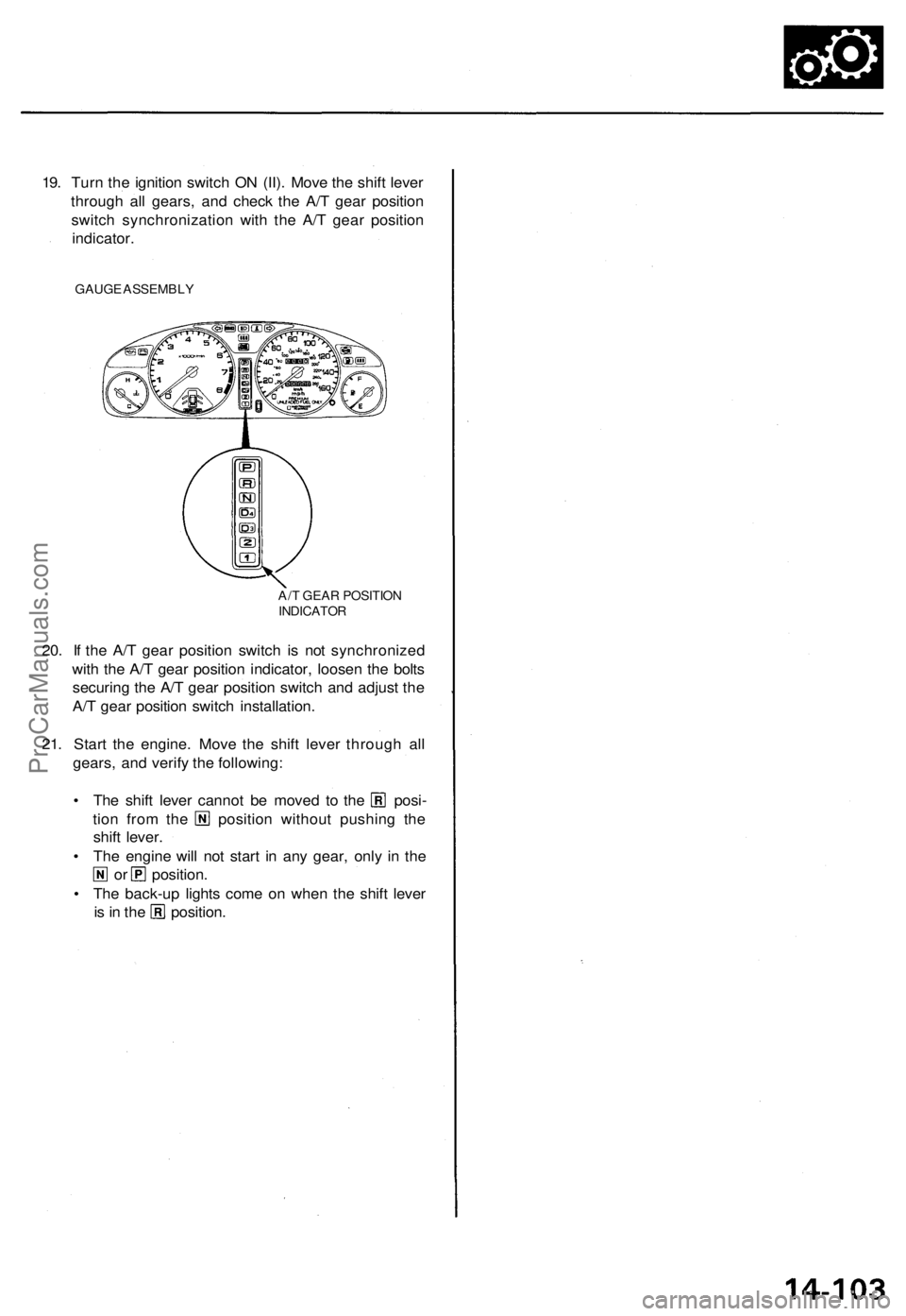
19. Turn the ignition switch ON (II). Move the shift lever
through all gears, and check the A/T gear position
switch synchronization with the A/T gear position
indicator.
GAUGE ASSEMBLY
20. If the A/T gear position switch is not synchronized
with the A/T gear position indicator, loosen the bolts
securing the A/T gear position switch and adjust the
A/T gear position switch installation.
21. Start the engine. Move the shift lever through all
gears, and verify the following:
• The shift lever cannot be moved to the posi-
tion from the position without pushing the
shift lever.
• The engine will not start in any gear, only in the
or position.
• The back-up lights come on when the shift lever
is in the position.
A/T GEAR POSITION
INDICATORProCarManuals.com
Page 320 of 1771
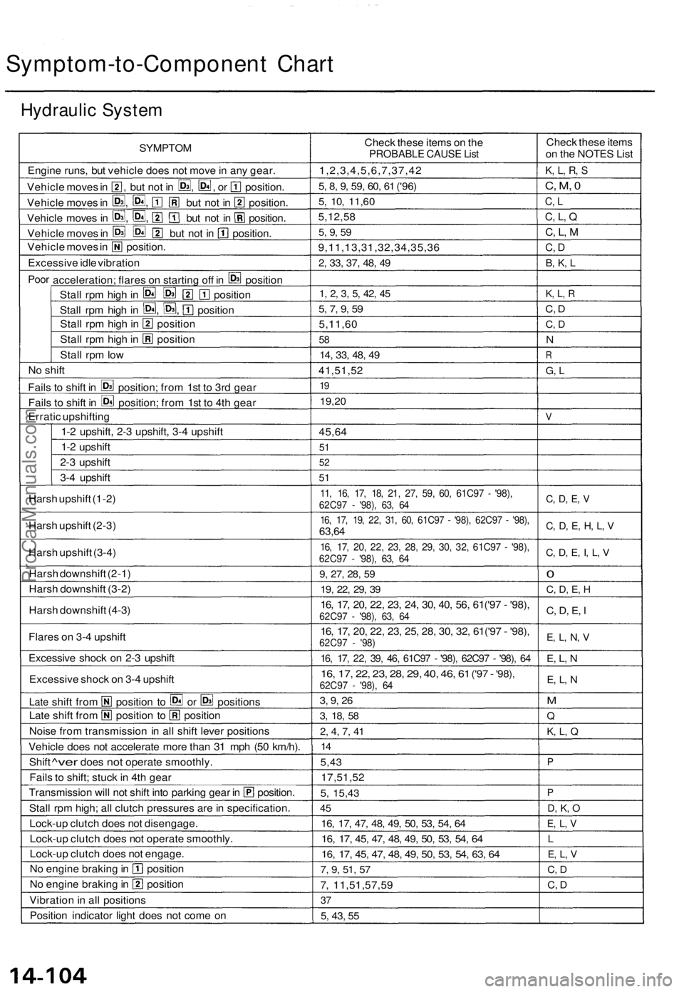
Symptom-to-Component Chart
Hydraulic System
SYMPTOM
Engine runs, but vehicle does not move in any gear.
Vehicle moves in , but not in , , or position.
Vehicle moves in , , but not in position.
Vehicle moves in , , but not in position.
Vehicle moves in but not in position.
Vehicle moves in position.
Excessive idle vibration
Poor
acceleration; flares on starting off in position
Stall rpm high in position
Stall rpm high in , , position
Stall rpm high in position
Stall rpm high in position
Stall rpm low
No shift
Fails to shift in position; from 1st to 3rd gear
Fails to shift in position; from 1st to 4th gear
Erratic upshifting
1-2 upshift, 2-3 upshift, 3-4 upshift
1-2 upshift
2-3 upshift
3-4 upshift
Harsh upshift (1-2)
Harsh upshift (2-3)
Harsh upshift (3-4)
Harsh downshift (2-1)
Harsh downshift (3-2)
Harsh downshift (4-3)
Flares on 3-4 upshift
Excessive shock on 2-3 upshift
Excessive shock on 3-4 upshift
Late
shift from position to or positions
Late shift from position to position
Noise from transmission in all shift lever positions
Vehicle does not accelerate more than 31 mph (50 km/h).
Shift
^ver
does
not
operate smoothly.
Fails to shift; stuck in 4th gear
Transmission will not shift into parking gear in position.
Stall
rpm high; all clutch pressures are in specification.
Lock-up clutch does not disengage.
Lock-up clutch does not operate smoothly.
Lock-up clutch does not engage.
No engine braking in position
No engine braking in position
Vibration in all positions
Position indicator light does not come on
Check these items on the
PROBABLE CAUSE List
1,2,3,4,5,6,7,37,42
5, 8, 9, 59, 60, 61
('96)
5, 10,
11,60
5,12,58
5, 9, 59
9,11,13,31,32,34,35,36
2, 33, 37, 48, 49
1, 2, 3, 5, 42, 45
5, 7, 9, 59
5,11,60
58
14, 33, 48, 49
41,51,52
19
19,20
45,64
51
52
51
11, 16, 17, 18, 21, 27, 59, 60, 61C97 - '98),
62C97 - '98), 63, 64
16, 17, 19, 22, 31, 60, 61C97 - '98), 62C97 - '98),
63,64
16, 17, 20, 22, 23, 28, 29, 30, 32, 61C97 - '98),
62C97 - '98), 63, 64
9, 27, 28, 59
19, 22, 29, 39
16, 17, 20, 22, 23, 24, 30, 40, 56, 61('97 - '98),
62C97 - '98), 63, 64
16, 17, 20, 22, 23, 25, 28, 30, 32, 61('97 - '98),
62C97 - '98)
16, 17, 22, 39, 46, 61C97 - '98), 62C97 - '98), 64
16, 17, 22, 23, 28, 29, 40, 46, 61
('97
-
'98),
62C97 - '98), 64
3, 9, 26
3, 18, 58
2, 4, 7, 41
14
5,43
17,51,52
5,
15,43
45
16, 17, 47, 48, 49, 50, 53, 54, 64
16, 17, 45, 47, 48, 49, 50, 53, 54, 64
16, 17, 45, 47, 48, 49, 50, 53, 54, 63, 64
7, 9, 51, 57
7, 11,51,57,59
37
5, 43, 55
Check these items
on the NOTES List
K, L, R, S
C, M, 0
C, L
C, L, Q
C, L, M
C, D
B, K, L
K, L, R
C, D
C, D
N
R
G, L
V
C, D, E, V
C, D, E, H, L, V
C, D, E, I, L, V
0
C, D, E, H
C, D, E, I
E, L, N, V
E, L, N
E, L, N
M
Q
K, L, Q
P
P
D, K, O
E, L, V
L
E, L, V
C, D
C, DProCarManuals.com
Page 361 of 1771
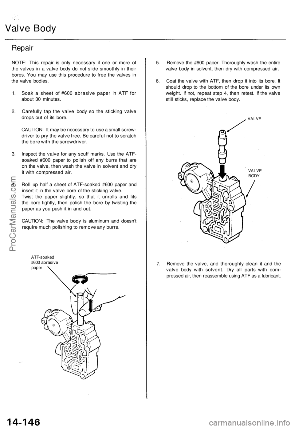
Valve Body
Repair
NOTE: This repair is only necessary if one or more of
the valves in a valve body do not slide smoothly in their
bores. You may use this procedure to free the valves in
the valve bodies.
1. Soak a sheet of #600 abrasive paper in ATF for
about 30 minutes.
2. Carefully tap the valve body so the sticking valve
drops out of its bore.
CAUTION: It may be necessary to use a small screw-
driver to pry the valve free. Be careful not to scratch
the bore with the screwdriver.
3. Inspect the valve for any scuff marks. Use the ATF-
soaked #600 paper to polish off any burrs that are
on the valve, then wash the valve in solvent and dry
it with compressed air.
4. Roll up half a sheet of ATF-soaked #600 paper and
insert it in the valve bore of the sticking valve.
Twist the paper slightly, so that it unrolls and fits
the bore tightly, then polish the bore by twisting the
paper as you push it in and out.
CAUTION: The valve body is aluminum and doesn't
require much polishing to remove any burrs.
ATF-soaked
#600 abrasive
paper
5. Remove the #600 paper. Thoroughly wash the entire
valve body in solvent, then dry with compressed air.
6. Coat the valve with ATF, then drop it into its bore. It
should drop to the bottom of the bore under its own
weight. If not, repeat step 4, then retest. If the valve
still sticks, replace the valve body.
VALVE
VALVE
BODY
7. Remove the valve, and thoroughly clean it and the
valve body with solvent. Dry all parts with com-
pressed air, then reassemble using ATF as a lubricant.ProCarManuals.com
Page 387 of 1771
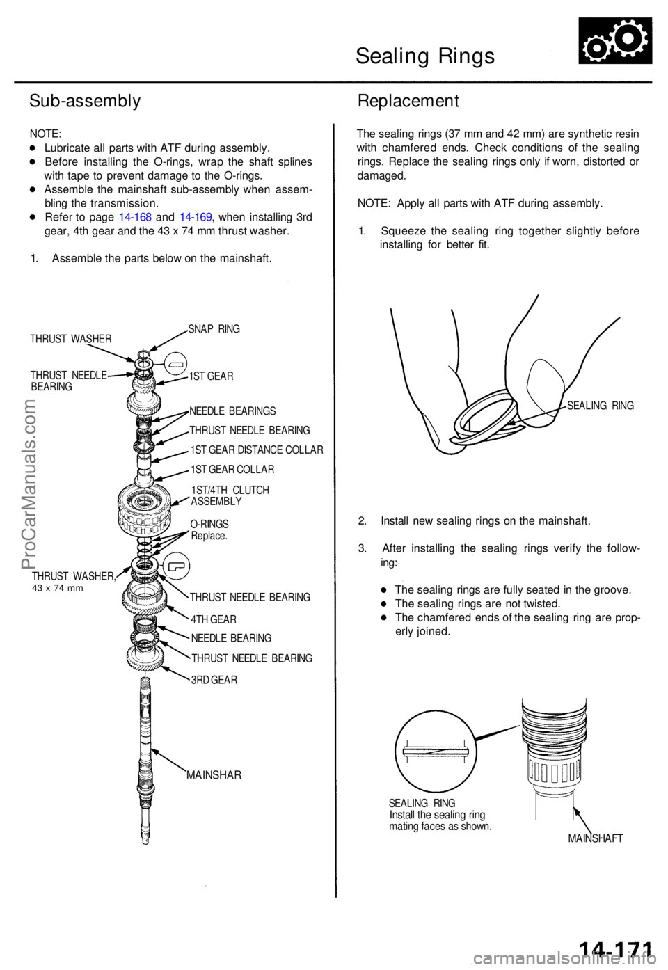
Sealing Ring s
Sub-assembl y
NOTE:
Lubricat e al l part s wit h AT F durin g assembly .
Befor e installin g th e O-rings , wra p th e shaf t spline s
wit h tap e t o preven t damag e t o th e O-rings .
Assembl e th e mainshaf t sub-assembl y whe n assem -
blin g th e transmission .
Refe r t o pag e 14-16 8 an d 14-169 , whe n installin g 3r d
gear , 4t h gea r an d th e 4 3 x 7 4 m m thrus t washer .
1 . Assembl e th e part s belo w o n th e mainshaft .
Replacemen t
THRUST WASHE R
THRUS T NEEDL E
BEARIN G
THRUS T WASHER ,
43 x 74 m m
SNA P RIN G
1S T GEA R
NEEDL E BEARING S
THRUS T NEEDL E BEARIN G
1S T GEA R DISTANC E COLLA R
1S T GEA R COLLA R
1ST/4T H CLUTC H
ASSEMBL Y
O-RING S
Replace .
THRUS T NEEDL E BEARIN G
4T H GEA R
NEEDL E BEARIN G
THRUS T NEEDL E BEARIN G
3R D GEA R
MAINSHA R
The sealin g ring s (3 7 m m an d 4 2 mm ) ar e syntheti c resi n
wit h chamfere d ends . Chec k condition s o f th e sealin g
rings . Replac e th e sealin g ring s onl y i f worn , distorte d o r
damaged .
NOTE : Appl y al l part s wit h AT F during assembly .
1 . Squeez e th e sealin g rin g togethe r slightl y befor e
installin g fo r bette r fit .
SEALIN G RIN G
2. Instal l ne w sealin g ring s o n th e mainshaft .
3 . Afte r installin g th e sealin g ring s verif y th e follow -
ing:
The sealin g ring s ar e full y seate d in th e groove .
Th e sealin g ring s ar e no t twisted .
Th e chamfere d end s o f th e sealin g rin g ar e prop -
erl y joined .
SEALIN G RIN GInstal l th e sealin g rin gmatin g face s a s shown .MAINSHAF T
ProCarManuals.com