1995 ACURA TL light
[x] Cancel search: lightPage 201 of 1771
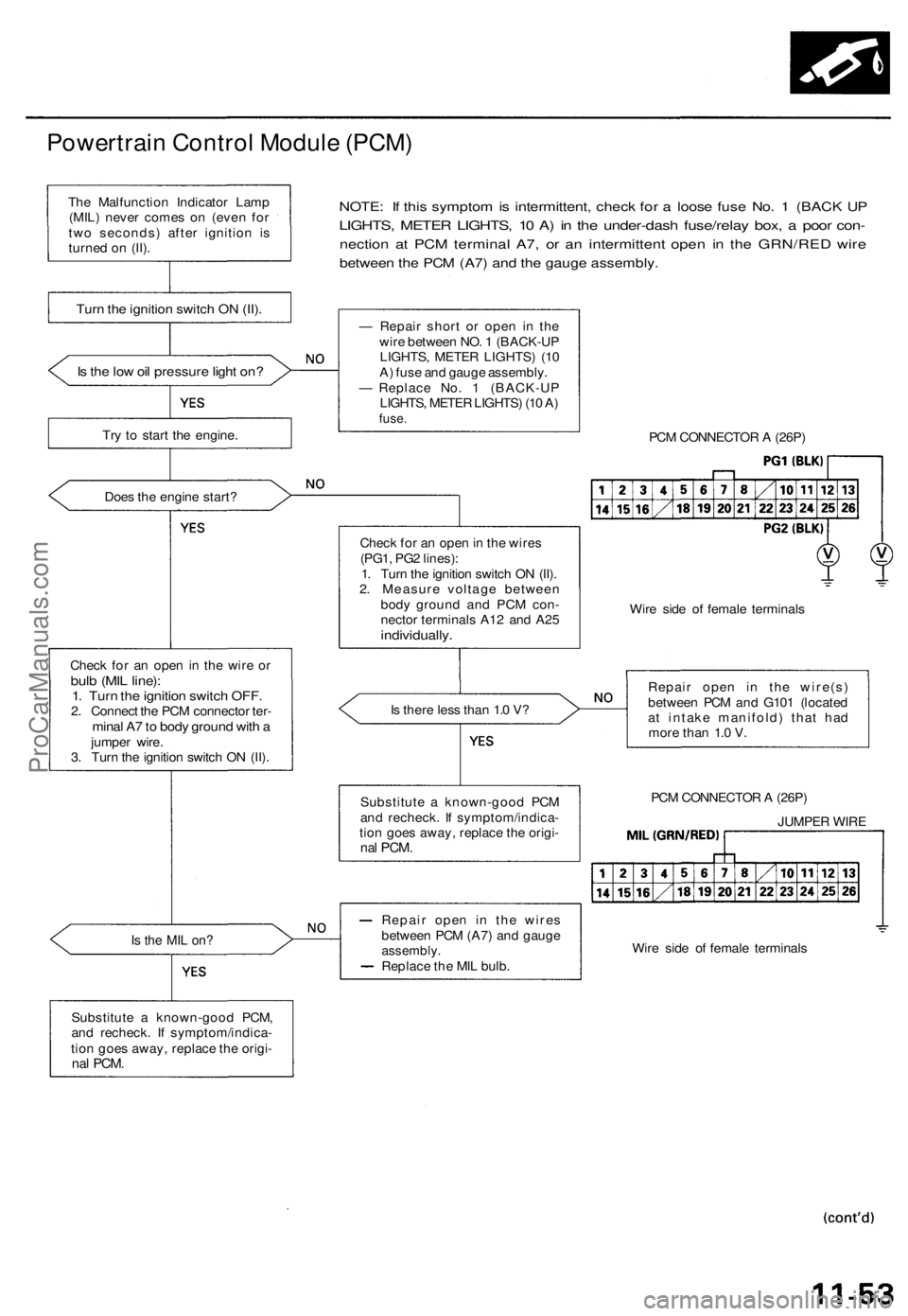
Powertrain Control Module (PCM)
NOTE: If this symptom is intermittent, check for a loose fuse No. 1 (BACK UP
LIGHTS, METER LIGHTS, 10 A) in the under-dash fuse/relay box, a poor con-
nection at PCM terminal A7, or an intermittent open in the GRN/RED wire
between the PCM (A7) and the gauge assembly.
Is the low oil pressure light on?
Try to start the engine.
Does the engine start?
Check for an open in the wire or
bulb (MIL line):
1. Turn the ignition switch OFF.
2. Connect the PCM connector ter-
minal A7 to body ground with a
jumper wire.
3. Turn the ignition switch ON (II).
Is the MIL on?
Substitute a known-good PCM,
and recheck. If symptom/indica-
tion goes away, replace the origi-
nal
PCM.
— Repair short or open in the
wire between NO. 1 (BACK-UP
LIGHTS, METER LIGHTS) (10
A) fuse and gauge assembly.
— Replace No. 1 (BACK-UP
LIGHTS, METER LIGHTS) (10 A)
fuse.
PCM CONNECTOR A (26P)
Check for an open in the wires
(PG1, PG2 lines):
1. Turn the ignition switch ON (II).
2. Measure voltage between
body ground and PCM con-
nector terminals A12 and A25
individually.
Wire side of female terminals
Is there less than 1.0 V?
Repair open in the wire(s)
between PCM and G101 (located
at intake manifold) that had
more than 1.0 V.
PCM CONNECTOR A (26P)
JUMPER WIRE
Wire side of female terminals
Repair open in the wires
between PCM (A7) and gauge
assembly.
Replace the MIL bulb.
Substitute a known-good PCM
and recheck. If symptom/indica-
tion goes away, replace the origi-
nal
PCM.
Turn the ignition switch ON (II).
The Malfunction Indicator Lamp
(MIL) never comes on (even for
two seconds) after ignition is
turned on (II).ProCarManuals.com
Page 209 of 1771
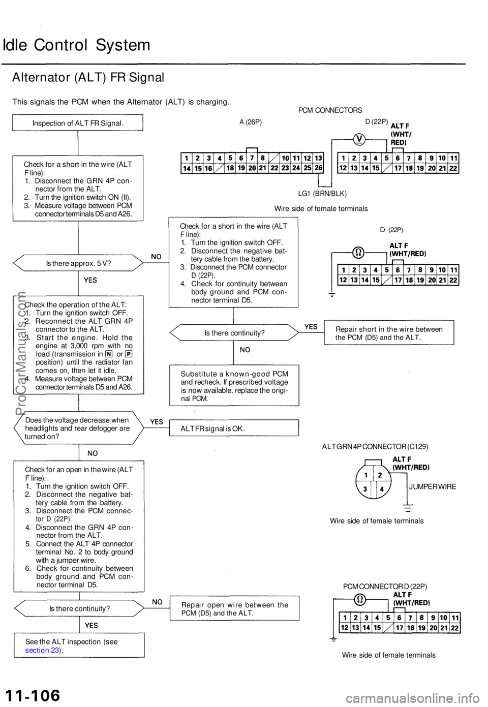
Idle Contro l Syste m
Alternato r (ALT ) F R Signa l
This signal s th e PC M whe n th e Alternato r (ALT ) i s charging .
Is ther e approx . 5 V ?
Chec k th e operatio n o f th e ALT :
1 . Tur n th e ignitio n switc h OFF .
2 . Reconnec t th e AL T GR N 4 P
connecto r t o th e ALT .
3 . Star t th e engine . Hol d th e
engin e a t 3,00 0 rp m wit h n o
loa d (transmissio n in o r
position ) unti l th e radiato r fa n
come s on , the n le t i t idle .
4 . Measur e voltag e betwee n PC M
connecto r terminal s D 5 an d A26 .
Doe s th e voltag e decreas e whe n
headlight s an d rea r defogge r ar e
turne d on ?
Chec k fo r a n ope n in th e wir e (AL T
F line) :
1 . Tur n th e ignitio n switc h OFF .
2 . Disconnec t th e negativ e bat -
ter y cabl e fro m th e battery .
3 . Disconnec t th e PC M connec -
tor D (22P) .4. Disconnec t th e GR N 4 P con -
necto r fro m th e ALT .
5 . Connec t th e AL T 4 P connecto r
termina l No . 2 to bod y groun d
with a jumpe r wire .6. Chec k fo r continuit y betwee n
bod y groun d an d PC M con -
necto r termina l D5 .
I s ther e continuity ?
Se e th e AL T inspectio n (se e
sectio n 23 ).
PC M CONNECTOR S
A (26P)D (22P )
LG1 (BRN/BLK )
Wire sid e o f femal e terminal s
Chec k fo r a shor t i n th e wir e (AL T
F line) :1. Tur n th e ignitio n switc h OFF .
2 . Disconnec t th e negativ e bat -
ter y cabl e fro m th e battery .
3 . Disconnec t th e PC M connecto r
D (22P) .4. Chec k fo r continuit y betwee n
bod y groun d an d PC M con -
necto r termina l D5 .
D (22P )
Is ther e continuity ? Repai
r shor t i n th e wir e betwee nthe PC M (D5 ) and th e ALT .
Substitut e a known-goo d PC M
an d recheck . I f prescribe d voltag e
i s no w available , replac e th e origi -
nal PCM .
ALT F R signa l i s OK .
ALT GR N 4P CONNECTO R (C129 )
JUMPE R WIR E
Wir e sid e o f femal e terminal s
Repai r ope n wir e betwee n th e
PC M (D5 ) and th e ALT .
Wire sid e o f femal e terminal s
PC
M CONNECTO R D (22P )
Chec
k fo r a shor t i n th e wir e (AL T
F line) :
1 . Disconnec t th e GR N 4 P con -
necto r fro m th e ALT .
2 . Tur n th e ignitio n switc h O N (II) .
3 . Measur e voltag e betwee n PC M
connecto r terminal s D 5 an d A26 .
Inspectio
n o f AL T F R Signal .
ProCarManuals.com
Page 215 of 1771
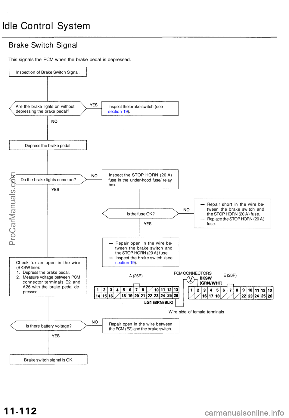
Idle Contro l Syste m
Brake Switc h Signa l
This signal s th e PC M whe n th e brak e peda l i s depressed .
Inspection o f Brak e Switc h Signal .
Ar e th e brak e light s o n withou t
depressin g th e brak e pedal ? Inspec
t th e brak e switc h (se e
sectio n 19 ).
Depres s th e brak e pedal .
D o th e brak e light s com e on ?
Is th e fus e OK ?
Chec k fo r a n ope n i n th e wir e
(BKS W line) :
1 . Depres s th e brak e pedal .
2 . Measur e voltag e betwee n PC M
connecto r terminal s E 2 an d
A2 6 wit h th e brak e peda l de -
pressed .
Repair shor t i n th e wire be-
twee n th e brak e switc h an d
th e STO P HOR N (2 0 A ) fuse .
Replac e th e STO P HOR N (2 0 A )
fuse .
Repai r ope n i n th e wir e be -
twee n th e brak e switc h an d
th e STO P HOR N (2 0 A ) fuse .
Inspec t th e brak e switc h (se e
sectio n 19 ).
A (26P )PCM CONNECTOR SE (26P)
Wire sid e o f femal e terminal s
I s ther e batter y voltage ? Repai
r ope n in th e wir e betwee n
th e PC M (E2 ) an d th e brak e switch .
Brak e switc h signa l i s OK . Inspec
t th e STO P HOR N (2 0 A )
fus e i n th e under-hoo d fuse / rela y
box.
ProCarManuals.com
Page 217 of 1771

Idle Contro l Syste m
Idle Spee d Settin g
Inspection/Adjustmen t
NOTE:
Before settin g th e idl e speed , chec k th e followin g
items :
— Th e MI L ha s no t bee n reporte d on .
— Ignitio n timin g
— Spar k plug s
— Ai r cleane r (ACL )
— PC V syste m
(Canada ) Pul l th e parkin g brak e leve r up . Star t th e
engine , the n chec k tha t th e headlight s ar e off .
1 . Star t th e engine . Hol d th e engin e a t 3,00 0 rp m wit h
no loa d (transmissio n i n o r position ) unti l th e
radiato r fa n come s on , the n le t i t idle .
2 . Connec t a OBDI I sca n too l (se e pag e 11-32 ) o r
tachometer .
• Connec t a tachomete r t o th e ignitio n contro l
module (ICM ) secondary , or.. .
TACHOMETE R
ICM
Remov e th e rubbe r ca p fro m th e tachomete r
connecto r an d connec t a tachometer .
TACHOMETE R TACHOMETE R
CONNECTOR
RUBBERCAP
3. Disconnec t th e IA C valv e connector .
4.
5 .
IA C VALV E
Start th e engin e wit h th e accelerato r peda l slightl y
depressed . Stabiliz e th e rp m a t 1,000 , the n slowl y
releas e th e peda l unti l th e engin e idles .
Check idlin g in no-loa d conditions : headlights , blow -
er fan , rea r defogger , radiato r fan , an d ai r conditione r
ar e no t operating .
Idl e spee d shoul d be :
480 5 0 rp m
(in o r position )
Adjus t th e idl e speed , i f necessary , b y turnin g th e
idl e adjustin g screw .
NOTE : Afte r adjustin g th e idl e spee d i n thi s step ,
rechec k th e ignitio n timin g (se e sectio n 23 ).
I f i t i s ou t o f spec , g o bac k t o ste p 4 .
IDL E ADJUSTIN G SCRE W
ProCarManuals.com
Page 218 of 1771
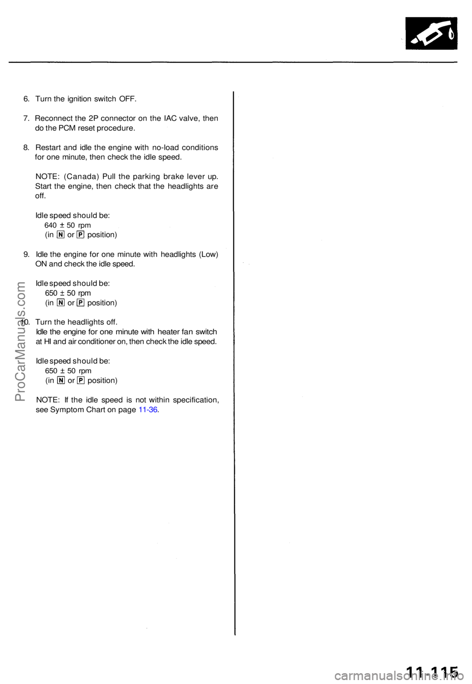
6. Tur n th e ignitio n switc h OFF .
7 . Reconnec t th e 2 P connecto r o n th e IA C valve , the n
d o th e PC M rese t procedure .
8 . Restar t an d idl e th e engin e wit h no-loa d condition s
fo r on e minute , the n chec k th e idl e speed .
NOTE : (Canada ) Pul l th e parkin g brak e leve r up .
Star t th e engine , the n chec k tha t th e headlight s ar e
off.
Idle spee d shoul d be :
640 5 0 rp m
(in o r position )
9 . Idl e th e engin e fo r on e minut e wit h headlight s (Low )
O N an d chec k th e idl e speed .
Idl e spee d shoul d be :
650 5 0 rp m
(in o r position )
10 . Tur n th e headlight s off .
Idle th e engin e fo r on e minut e wit h heate r fa n switc h
at H I an d ai r conditione r on , the n chec k th e idl e speed .
Idl e spee d shoul d be :
650 5 0 rp m
(in o r position )
NOTE : I f th e idl e spee d i s no t withi n specification ,
se e Sympto m Char t o n pag e 11-36 .
ProCarManuals.com
Page 242 of 1771
Intake Ai r Syste m
Throttl e Bod y
Descriptio n
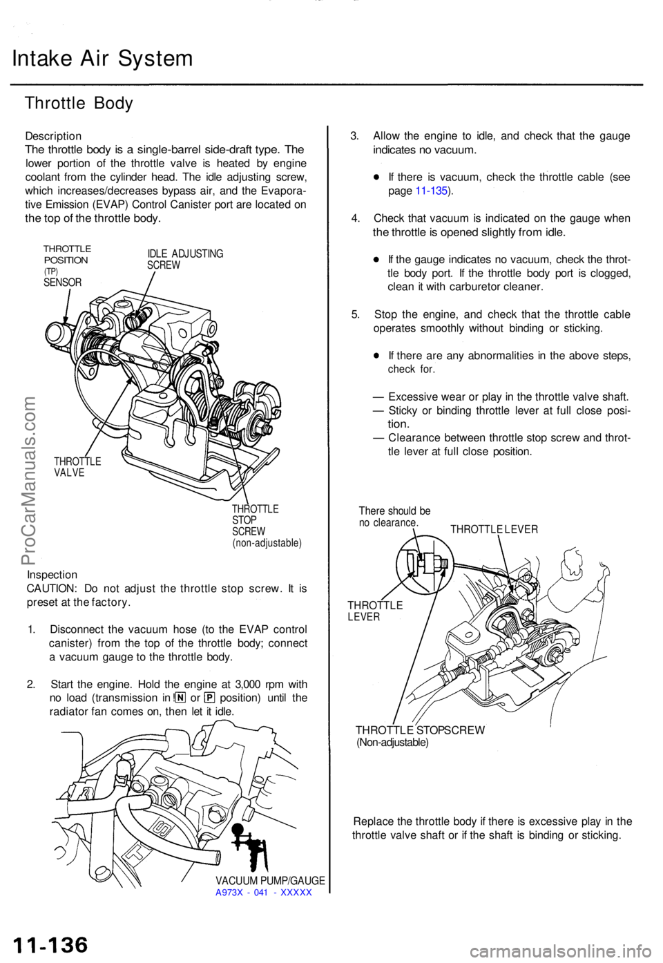
The throttl e bod y i s a single-barre l side-draf t type . Th e
lowe r portio n o f th e throttl e valv e i s heate d b y engin e
coolan t fro m th e cylinde r head . Th e idl e adjustin g screw ,
whic h increases/decrease s bypas s air , an d th e Evapora -
tiv e Emissio n (EVAP ) Contro l Caniste r por t ar e locate d o n
the to p o f th e throttl e body .
THROTTL EPOSITION(TP)SENSO R
IDLE ADJUSTIN GSCREW
THROTTL E
VALV E
THROTTLE
STOPSCRE W
(non-adjustable )
Inspection
CAUTION : D o no t adjus t th e throttl e sto p screw . I t i s
prese t a t th e factory .
1 . Disconnec t th e vacuu m hos e (t o th e EVA P contro l
canister ) fro m th e to p o f th e throttl e body ; connec t
a vacuu m gaug e t o th e throttl e body .
2 . Star t th e engine . Hol d th e engine at 3,00 0 rp m wit h
no loa d (transmissio n i n ! o r position ) unti l th e
radiato r fa n come s on , the n le t i t idle .
VACUU M PUMP/GAUG EA973X - 04 1 - XXXX X
3. Allo w th e engin e t o idle , an d chec k tha t th e gaug e
indicate s n o vacuum .
If ther e i s vacuum , chec k th e throttl e cabl e (se e
pag e 11-135 ).
4 . Chec k tha t vacuu m is indicate d o n th e gaug e whe n
the throttl e is opene d slightl y fro m idle .
If th e gaug e indicate s n o vacuum , chec k th e throt -
tl e bod y port . I f th e throttl e bod y por t i s clogged ,
clea n i t wit h carbureto r cleaner .
5 . Sto p th e engine , an d chec k tha t th e throttl e cabl e
operates smoothly without bindin g o r sticking .
I f ther e ar e an y abnormalitie s i n th e abov e steps ,
check for .
— Excessiv e wea r o r pla y i n th e throttl e valv e shaft .
— Stick y o r bindin g throttl e leve r a t ful l close posi-
tion.
— Clearanc e betwee n throttl e sto p scre w an d throt -
tl e leve r a t ful l clos e position .
There shoul d b eno clearance .THROTTLE LEVE R
THROTTL ELEVER
THROTTL E STO P SCRE W(Non-adjustable )
Replace th e throttl e bod y i f ther e is excessiv e pla y i n th e
throttl e valv e shaf t o r i f th e shaf t i s bindin g o r sticking .
ProCarManuals.com
Page 252 of 1771
Emission Control System
Positive Crankcase Ventilation (PCV) System
Description
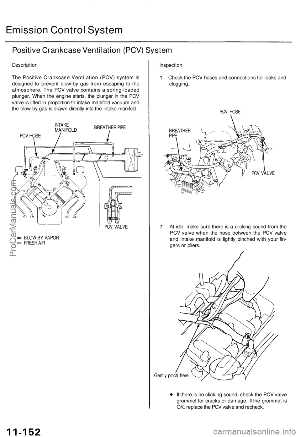
The Positive Crankcase Ventilation (PCV) system is
designed to prevent blow-by gas from escaping to the
atmosphere. The PCV valve contains a spring-loaded
plunger. When the engine starts, the plunger in the PCV
valve is lifted in proportion to intake manifold vacuum and
the blow-by gas is drawn directly into the intake manifold.
INTAKE
MANIFOLD
BREATHER PIPE
PCV HOSE
PCV VALVE
BLOW-BY VAPOR
FRESH AIR
Inspection
1. Check the PCV hoses and connections for leaks and
clogging.
PCV HOSE
BREATHER
PIPE
PCV VALVE
2.
At idle, make sure there is a clicking sound from the
PCV valve when the hose between the PCV valve
and intake manifold is lightly pinched with your fin-
gers or pliers.
Gently pinch here
If there is no clicking sound, check the PCV valve
grommet for cracks or damage. If the grommet is
OK, replace the PCV valve and recheck.ProCarManuals.com
Page 296 of 1771
Partial Lock-up
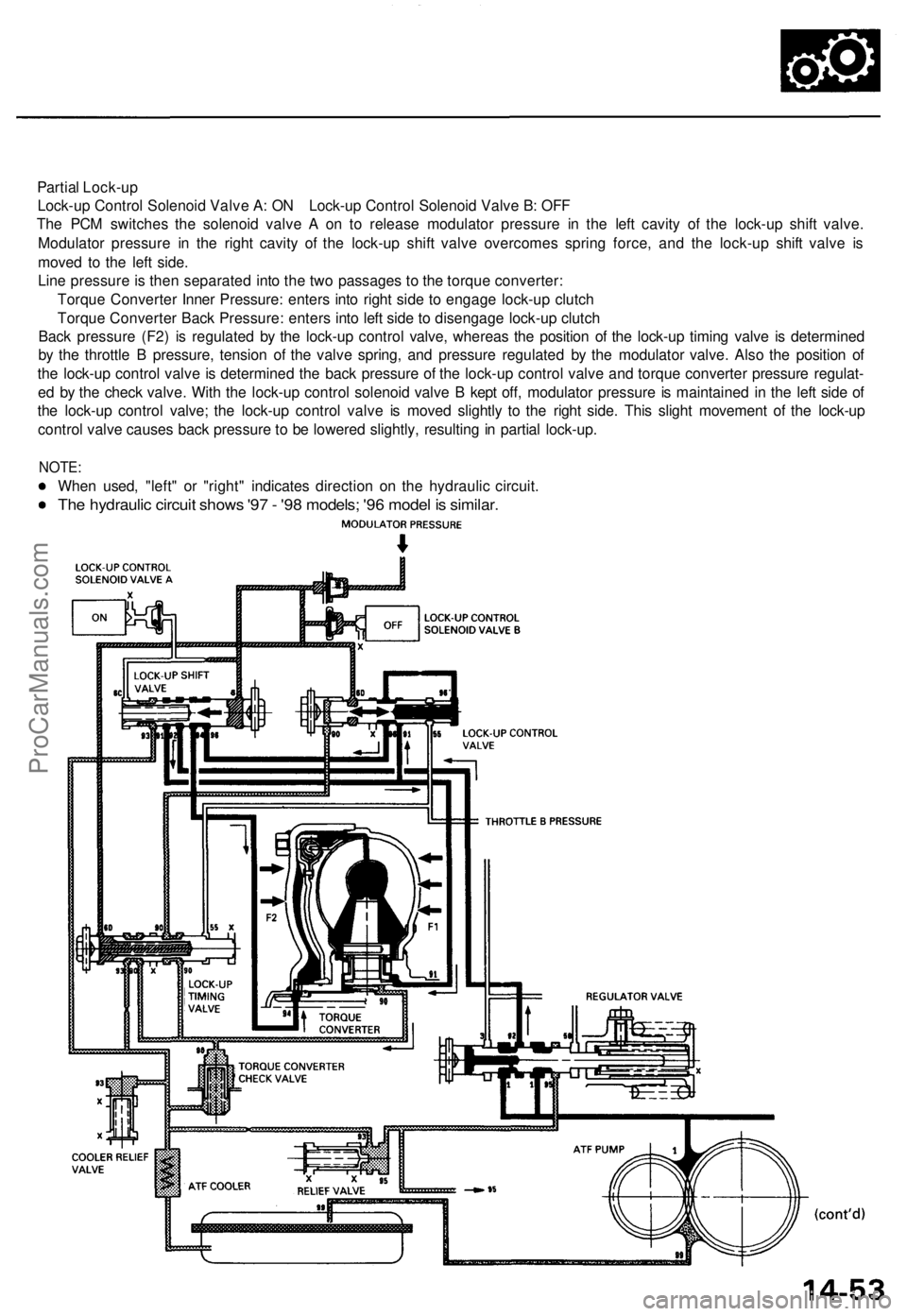
Lock-up Control Solenoid Valve A: ON Lock-up Control Solenoid Valve B: OFF
The PCM switches the solenoid valve A on to release modulator pressure in the left cavity of the lock-up shift valve.
Modulator pressure in the right cavity of the lock-up shift valve overcomes spring force, and the lock-up shift valve is
moved to the left side.
Line pressure is then separated into the two passages to the torque converter:
Torque Converter Inner Pressure: enters into right side to engage lock-up clutch
Torque Converter Back Pressure: enters into left side to disengage lock-up clutch
Back pressure (F2) is regulated by the lock-up control valve, whereas the position of the lock-up timing valve is determined
by the throttle B pressure, tension of the valve spring, and pressure regulated by the modulator valve. Also the position of
the lock-up control valve is determined the back pressure of the lock-up control valve and torque converter pressure regulat-
ed by the check valve. With the lock-up control solenoid valve B kept off, modulator pressure is maintained in the left side of
the lock-up control valve; the lock-up control valve is moved slightly to the right side. This slight movement of the lock-up
control valve causes back pressure to be lowered slightly, resulting in partial lock-up.
NOTE:
When used, "left" or "right" indicates direction on the hydraulic circuit.
The hydraulic circuit shows '97 - '98 models; '96 model is similar.ProCarManuals.com