1995 ACURA TL ESP
[x] Cancel search: ESPPage 420 of 1771
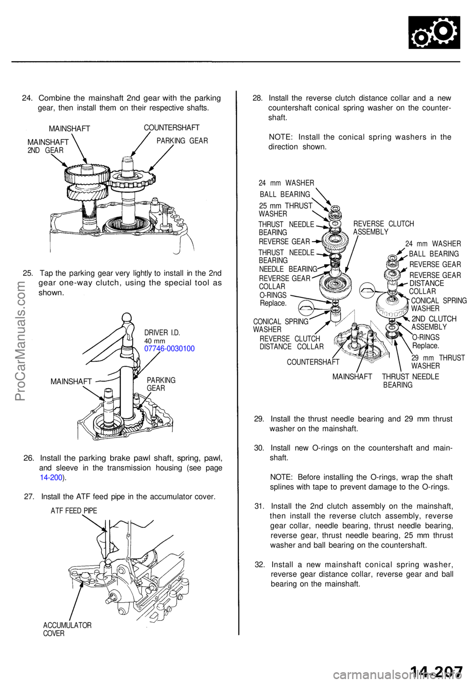
24. Combin e th e mainshaf t 2n d gea r wit h th e parkin g
gear, the n instal l the m o n thei r respectiv e shafts .
MAINSHAF T
MAINSHAF T
2ND GEA R
COUNTERSHAF T
PARKING GEA R
25. Ta p th e parkin g gea r ver y lightl y t o instal l i n th e 2n d
gea r one-wa y clutch , usin g th e specia l too l a s
shown .
DRIVE R I.D .40 m m07746-003010 0
MAINSHAFTPARKING
GEA R
26. Instal l th e parkin g brak e paw l shaft , spring , pawl ,
and sleev e i n th e transmissio n housin g (se e pag e
14-200 ).
27 . Instal l th e AT F fee d pip e i n th e accumulato r cover .
ATF FEE D PIP E
ACCUMULATO R
COVE R
28. Instal l th e revers e clutc h distanc e colla r an d a ne w
countershaf t conica l sprin g washe r o n th e counter -
shaft .
NOTE : Instal l th e conica l sprin g washer s i n th e
directio n shown .
24 m m WASHE R
BAL L BEARING
THRUS T NEEDL E
BEARIN G
REVERS E GEA R
THRUS T NEEDL E
BEARIN G
NEEDL E BEARIN G
REVERS E GEA R
COLLA R
O-RING S
Replace .
CONICA L SPRIN G
WASHE R
REVERS E CLUTC H
DISTANC E COLLA R
COUNTERSHAF TREVERS
E CLUTC H
ASSEMBL Y
24 m m WASHE R
BAL L BEARIN G
REVERS E GEA R
REVERS E GEA R
DISTANC ECOLLAR
CONICA L SPRIN G
WASHE R
2ND CLUTC HASSEMBL Y
O-RING S
Replace .
29 m m THRUS T
WASHE R
MAINSHAF T THRUS T NEEDL EBEARIN G
29. Instal l th e thrus t needl e bearin g an d 2 9 m m thrus t
washe r o n th e mainshaft .
30 . Instal l ne w O-ring s o n th e countershaf t an d main -
shaft .
NOTE : Befor e installin g th e O-rings , wra p th e shaf t
spline s wit h tap e t o preven t damag e t o th e O-rings .
31 . Instal l th e 2n d clutc h assembl y o n th e mainshaft ,
the n instal l th e revers e clutc h assembly , revers e
gea r collar , needl e bearing , thrus t needl e bearing ,
revers e gear , thrus t needl e bearing , 2 5 m m thrus t
washe r an d bal l bearin g o n th e countershaft .
32 . Instal l a ne w mainshaf t conica l sprin g washer ,
revers e gea r distanc e collar , revers e gea r an d bal l
bearin g o n th e mainshaft .
25 m m THRUS TWASHER
ProCarManuals.com
Page 471 of 1771
Power Steering Hoses and Pipes
Replacement
NOTE:
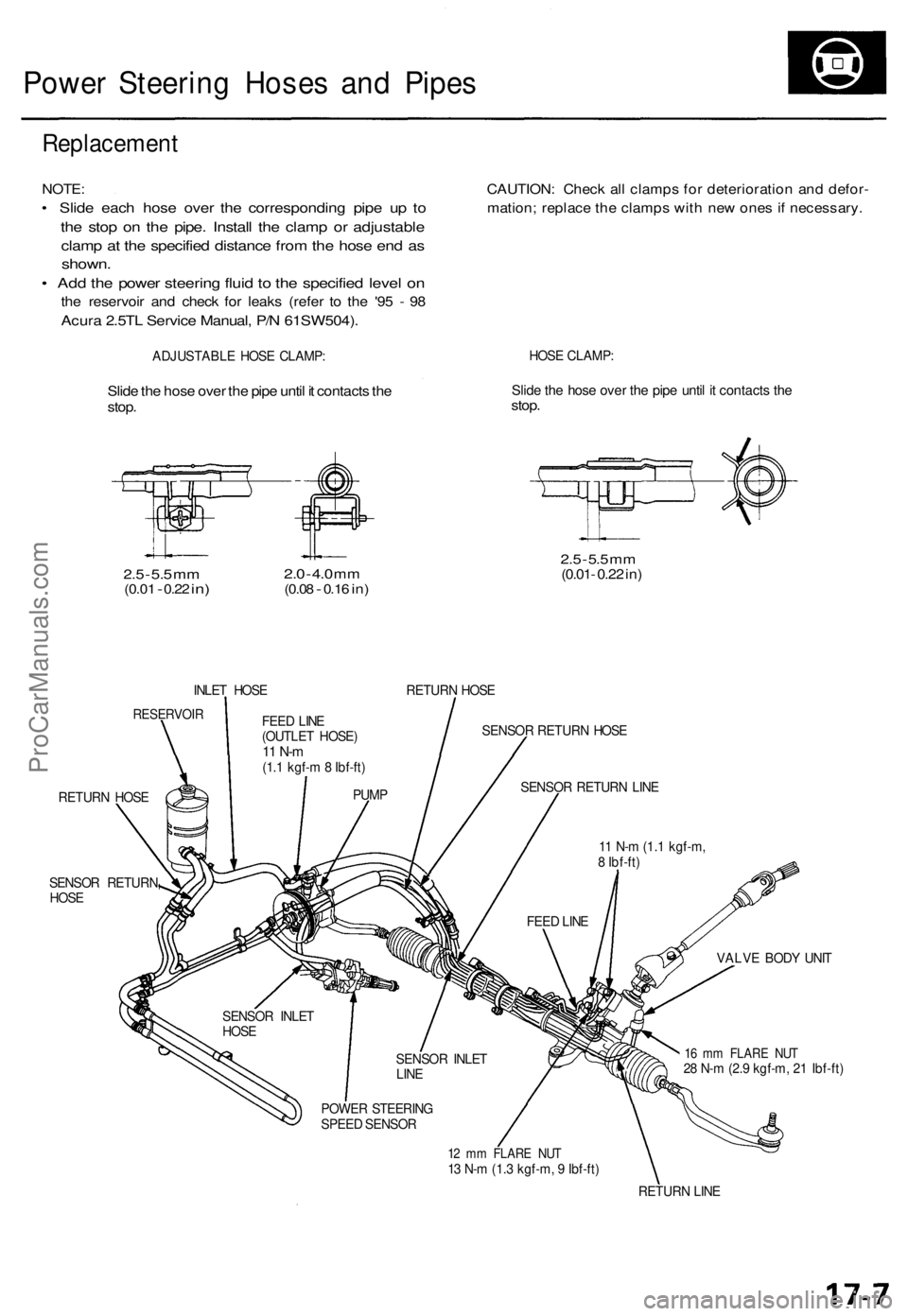
• Slide each hose over the corresponding pipe up to
the stop on the pipe. Install the clamp or adjustable
clamp at the specified distance from the hose end as
shown.
• Add the power steering fluid to the specified level on
the reservoir and check for leaks (refer to the '95 - 98
Acura 2.5TL Service Manual, P/N 61SW504).
CAUTION: Check all clamps for deterioration and defor-
mation; replace the clamps with new ones if necessary.
ADJUSTABLE HOSE CLAMP:
HOSE CLAMP:
Slide the hose over the pipe until it contacts the
stop.
Slide the hose over the pipe until it contacts the
stop.
2.5
-
5.5
mm
(0.01
-
0.22
in)
2.0
-
4.0
mm
(0.08
-
0.16
in)
2.5
-
5.5
mm
(0.01- 0.22 in)
INLET HOSE
RETURN HOSE
RESERVOIR
SENSOR RETURN HOSE
RETURN HOSE
SENSOR RETURN
HOSE
VALVE BODY UNIT
16 mm FLARE NUT
28 N-m (2.9 kgf-m, 21 Ibf-ft)
12 mm FLARE NUT
13 N-m (1.3 kgf-m, 9 Ibf-ft)
RETURN LINE
FEED LINE
(OUTLET HOSE)
11 N-m
(1.1 kgf-m 8 Ibf-ft)
PUMP
SENSOR INLET
HOSE
SENSOR INLET
LINE
POWER STEERING
SPEED SENSOR
FEED LINE
11 N-m (1.1 kgf-m,
8 Ibf-ft)
SENSOR RETURN LINEProCarManuals.com
Page 481 of 1771
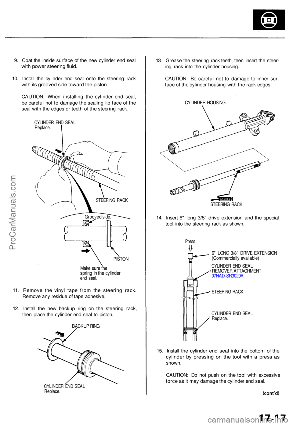
9. Coa t th e insid e surfac e o f th e ne w cylinde r en d sea l
with powe r steerin g fluid .
10. Instal l th e cylinde r en d sea l ont o th e steerin g rac k
with it s groove d sid e towar d th e piston .
CAUTION : Whe n installin g th e cylinde r en d seal ,
b e carefu l no t t o damag e th e sealin g li p fac e o f th e
sea l wit h th e edge s o r teet h o f th e steerin g rack .
CYLINDE R EN D SEA LReplace .
PISTON
CYLINDE R EN D SEA LReplace .
13. Greas e th e steerin g rac k teeth , the n inser t th e steer -
in g rac k int o th e cylinde r housing .
CAUTION : B e carefu l no t t o damag e t o inne r sur -
fac e o f th e cylinde r housin g wit h th e rac k edges .
CYLINDE R HOUSIN G
STEERIN G RAC K
14. Inser t 6 " lon g 3/8 " driv e extensio n an d th e specia l
tool int o th e steerin g rac k a s shown .
Press
. 6 " LON G 3/8 " DRIV E EXTENSIO N(Commerciall y available )
CYLINDER EN D SEA L• REMOVE R ATTACHMEN T07NAD-SR3020 A
• STEERIN G RAC K
CYLINDE R EN D SEA L' Replace .
15. Instal l th e cylinde r en d sea l int o th e botto m o f th e
cylinde r b y pressin g o n th e too l with a press a s
shown .
CAUTION : D o no t pus h o n th e too l wit h excessiv e
forc e a s it ma y damag e th e cylinde r en d seal .
STEERIN G RAC K
Groove d side .
Make sur e th esprin g in th e cylinde rend seal .
11. Remov e th e viny l tap e fro m th e steerin g rack .
Remov e an y residu e o f tap e adhesive .
12 . Instal l th e ne w backu p rin g o n th e steerin g rack ,
the n plac e th e cylinde r en d sea l t o piston .
BACKU P RIN G
ProCarManuals.com
Page 483 of 1771
24. Selec t th e 4 4 m m shim(s) .
NOTE : Onl y reinstal l th e origina l 4 4 m m shim(s ) whe n
th e steerin g gearbo x i s reassemble d withou t replacin g
th e pinio n shaft , valv e housing , an d gearbo x housin g
wit h ne w ones .
I f th e pinio n shaft , valv e housing , an d gearbo x housin g
ar e replaced , selec t th e ne w shim(s ) a s follows .
Shim selection :
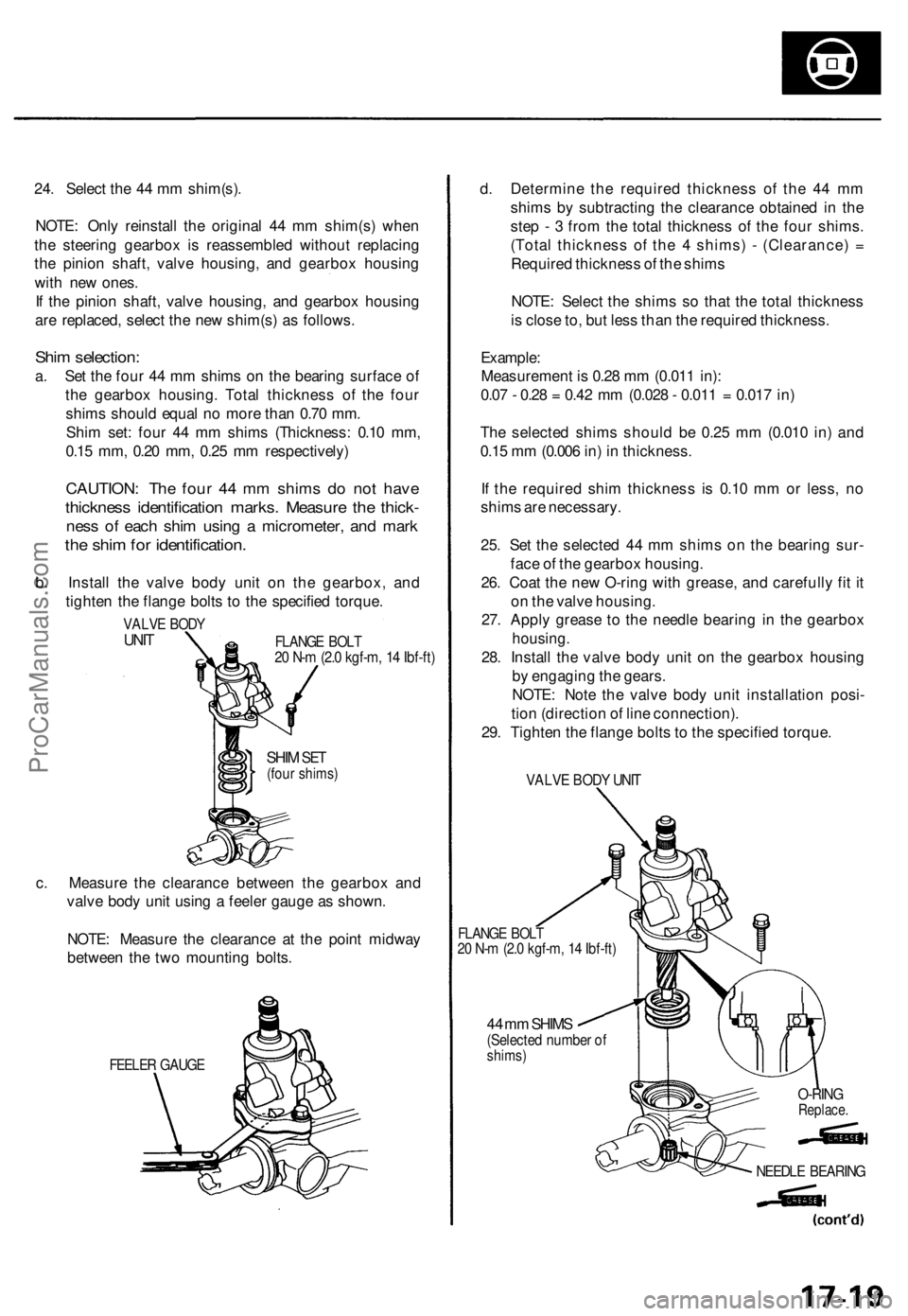
a. Se t th e fou r 4 4 m m shim s o n th e bearin g surfac e o f
th e gearbo x housing . Tota l thicknes s o f th e fou r
shim s shoul d equa l n o mor e tha n 0.7 0 mm .
Shi m set : fou r 4 4 m m shim s (Thickness : 0.1 0 mm ,
0.1 5 mm , 0.2 0 mm , 0.2 5 m m respectively )
CAUTION: Th e fou r 4 4 m m shim s d o no t hav e
thicknes s identificatio n marks . Measur e th e thick -
ness o f eac h shi m usin g a micrometer , an d mar k
the shi m fo r identification .
b. Instal l th e valv e bod y uni t o n th e gearbox , an d
tighte n th e flang e bolt s t o th e specifie d torque .
VALVE BOD YUNITFLANG E BOL T20 N- m (2. 0 kgf-m , 1 4 Ibf-ft )
SHIM SET(fou r shims )
c. Measur e th e clearanc e betwee n th e gearbo x an d
valv e bod y uni t usin g a feele r gaug e a s shown .
NOTE : Measur e th e clearanc e a t th e poin t midwa y
betwee n th e tw o mountin g bolts .
FEELE R GAUG E
d. Determin e th e require d thicknes s o f th e 4 4 m m
shim s b y subtractin g th e clearanc e obtaine d in th e
ste p - 3 fro m th e tota l thicknes s o f th e fou r shims .
(Tota l thicknes s o f th e 4 shims ) - (Clearance ) =
Require d thicknes s o f th e shim s
NOTE : Selec t th e shim s s o tha t th e tota l thicknes s
i s clos e to , bu t les s tha n th e require d thickness .
Example :
Measuremen t i s 0.2 8 m m (0.01 1 in) :
0.0 7 - 0.2 8 = 0.4 2 m m (0.02 8 - 0.01 1 = 0.01 7 in )
Th e selecte d shim s shoul d b e 0.2 5 m m (0.01 0 in ) an d
0.1 5 m m (0.00 6 in ) i n thickness .
I f th e require d shi m thicknes s i s 0.1 0 m m o r less , n o
shim s ar e necessary .
25 . Se t th e selecte d 4 4 m m shim s o n th e bearin g sur -
fac e o f th e gearbo x housing .
26 . Coa t th e ne w O-rin g wit h grease , an d carefull y fi t i t
o n th e valv e housing .
27 . Appl y greas e t o th e needl e bearin g i n th e gearbo x
housing.
28. Instal l th e valv e bod y uni t o n th e gearbo x housin g
b y engagin g th e gears .
NOTE : Not e th e valv e bod y uni t installatio n posi -
tio n (directio n o f lin e connection) .
29 . Tighte n th e flang e bolt s to th e specifie d torque .
VALVE BOD Y UNI T
FLANG E BOL T20 N- m (2. 0 kgf-m , 1 4 Ibf-ft )
44 m m SHIM S(Selecte d numbe r o fshims )
O-RINGReplace .
NEEDLE BEARIN G
ProCarManuals.com
Page 493 of 1771
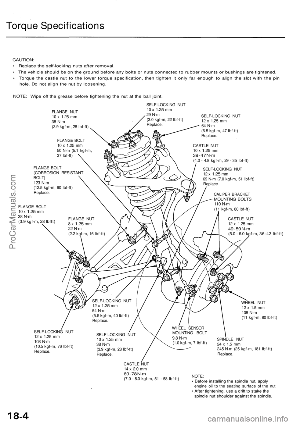
Torque Specification s
CAUTION:
• Replac e th e self-lockin g nut s afte r removal .
• Th e vehicl e shoul d b e o n th e groun d befor e an y bolt s o r nut s connecte d t o rubbe r mount s o r bushing s ar e tightened .
• Torqu e th e castl e nu t t o th e lowe r torqu e specification , the n tighte n i t onl y fa r enoug h t o alig n th e slo t wit h th e pi n
hole . D o no t alig n th e nu t b y loosening .
NOTE : Wip e of f th e greas e befor e tightenin g th e nu t a t th e bal l joint .
SELF-LOCKIN G NU T10 x 1.2 5 mm29 N- m(3.0 kgf-m , 2 2 Ibf-ft )Replace .
FLANGE BOL T10 x 1.2 5 mm38 N- m(3.9 kgf-m , 2 8 Ibfft )
SELF-LOCKIN G NU T12 x 1.2 5 mm
- 6 4 N- m
(6.5 kgf-m , 4 7 Ibf-ft )Replace .
CASTLE NU T10 x 1.2 5 mm39 - 4 7 N- m(4. 0 - 4. 8 kgf-m , 2 9 - 3 5 Ibf-ft )
SELF-LOCKIN G NU T
12 x 1.2 5 mm69 N- m (7. 0 kgf-m , 5 1 Ibf-ft )
Replace .
CALIPER BRACKE TMOUNTING BOLT S110 N- m(11 kgf-m , 8 0 Ibf-ft )
CASTL E NU T
12 x 1.2 5 mm49 - 5 9 N- m(5. 0 - 6. 0 kgf-m , 36-4 3 Ibf-ft )
SELF-LOCKIN G NU T12 x 1.2 5 mm103 N- m(10. 5 kgf-m , 7 6 Ibf-ft )Replace .
SELF-LOCKIN G NU T10 x 1.2 5 mm38 N- m(3.9 kgf-m , 2 8 Ibf-ft )Replace .
CASTLE NU T14 x 2. 0 m m69 - 7 8 N- m(7. 0 - 8. 0 kgf-m , 5 1 - 5 8 Ibf-ft ) WHEE
L NU T
12 x 1. 5 m m108 N- m(11 kgf-m , 8 0 Ibf-ft )
SPINDL E NU T
24 x 1. 5 m m245 N- m (2 5 kgf-m , 18 1 Ibf-ft )Replace .
NOTE:• Befor e installin g th e spindl e nut , appl yengin e oi l t o th e seatin g surfac e o f th e nut .• Afte r tightening , us e a drif t t o stak e th espindl e nu t shoulde r agains t th e spindle .
FLANGE NU T10 x 1.2 5 mm38 N- m(3.9 kgf-m , 2 8 Ibf-ft )
FLANG E BOL T
10 x 1.2 5 mm50 N- m (5. 1 kgf-m ,
3 7 Ibf-ft )
FLANG E NU T
8 x 1.2 5 mm22 N- m(2.2 kgf-m , 1 6 Ibf-ft )
FLANG
E BOL T
(CORROSIO N RESISTAN T
BOLT)123 N- m(12. 5 kgf-m , 9 0 Ibf-ft )Replace .
WHEEL SENSO R
MOUNTIN G BOL T
9.8 N- m(1.0 kgf-m , 7 Ibf-ft )
SELF-LOCKIN
G NU T
12 x 1.2 5 mm54 N- m(5.5 kgf-m , 4 0 Ibf-ft )Replace .
ProCarManuals.com
Page 495 of 1771
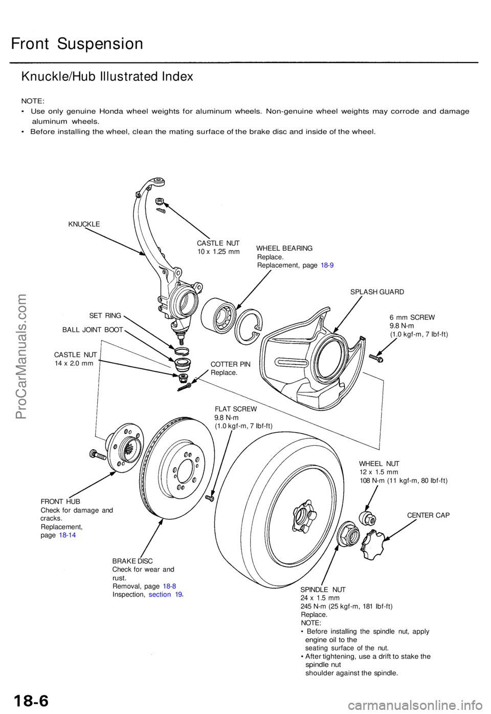
Front Suspensio n
Knuckle/Hu b Illustrated Index
NOTE :
• Us e onl y genuin e Hond a whee l weight s fo r aluminu m wheels . Non-genuin e whee l weight s ma y corrod e an d damag e
aluminu m wheels .
• Befor e installin g th e wheel , clea n th e matin g surfac e o f th e brak e dis c an d insid e o f th e wheel .
KNUCKL E
SET RIN G
BAL L JOIN T BOO T
CASTL E NU T
14 x 2. 0 m m
FRON T HU B
Chec k fo r damag e an d
cracks .Replacement ,
pag e 18-1 4 WHEE
L BEARIN G
Replace.Replacement , pag e 18- 9
SPLAS H GUAR D
6 m m SCRE W
9.8 N- m(1.0 kgf-m , 7 Ibf-ft )
WHEE L NU T
12 x 1. 5 m m108 N- m (1 1 kgf-m , 8 0 Ibf-ft )
CENTE R CA P
BRAK E DIS C
Chec k fo r wea r an d
rust .Removal , pag e 18- 8
Inspection , sectio n 1 9 SPINDL
E NU T
24 x 1. 5 m m245 N- m (2 5 kgf-m , 18 1 Ibf-ft )
Replace .
NOTE :
• Befor e installin g th e spindl e nut , appl y
engine oi l t o th eseatin g surfac e o f th e nut .• Afte r tightening , us e a drif t t o stak e th espindl e nu tshoulde r agains t th e spindle .
CASTLE NU T10 x 1.2 5 mm
COTTE R PI N
Replace .
FLAT SCRE W9.8 N- m(1.0 kgf-m , 7 Ibf-ft )
ProCarManuals.com
Page 684 of 1771

Under-hood Emissions Control Label
VACUUM HOSE ROUTING DIAGRAM
Emission Group Identification
(1997 model)
VEHICLE EMISSION CONTROL INFORMATION
50ST (50 States):
THIS VEHICLE CONFORMS TO THE U.S. EPA AND THE
STATE OF CALIFORNIA REGULATIONS APPLICABLE TO
1997 MODEL YEAR NEW MOTOR VEHICLES.
49ST (49 States/Federal):
THIS VEHICLE CONFORMS TO THE U.S. EPA REGULA-
TIONS APPLICABLE TO 1997 MODEL YEAR NEW
MOTOR VEHICLES.
CAL (California):
THIS VEHICLE CONFORMS TO THE U.S. EPA AND
STATE OF CALIFORNIA REGULATIONS APPLICABLE TO
1997 MODEL YEAR NEW PASSENGER CARS PROVIDED
THAT THIS VEHICLE IS ONLY INTRODUCED INTO COM-
MERCE FOR SALE IN THE STATE OF CALIFORNIA.
Engine and Evaporative FamiliesProCarManuals.com
Page 787 of 1771
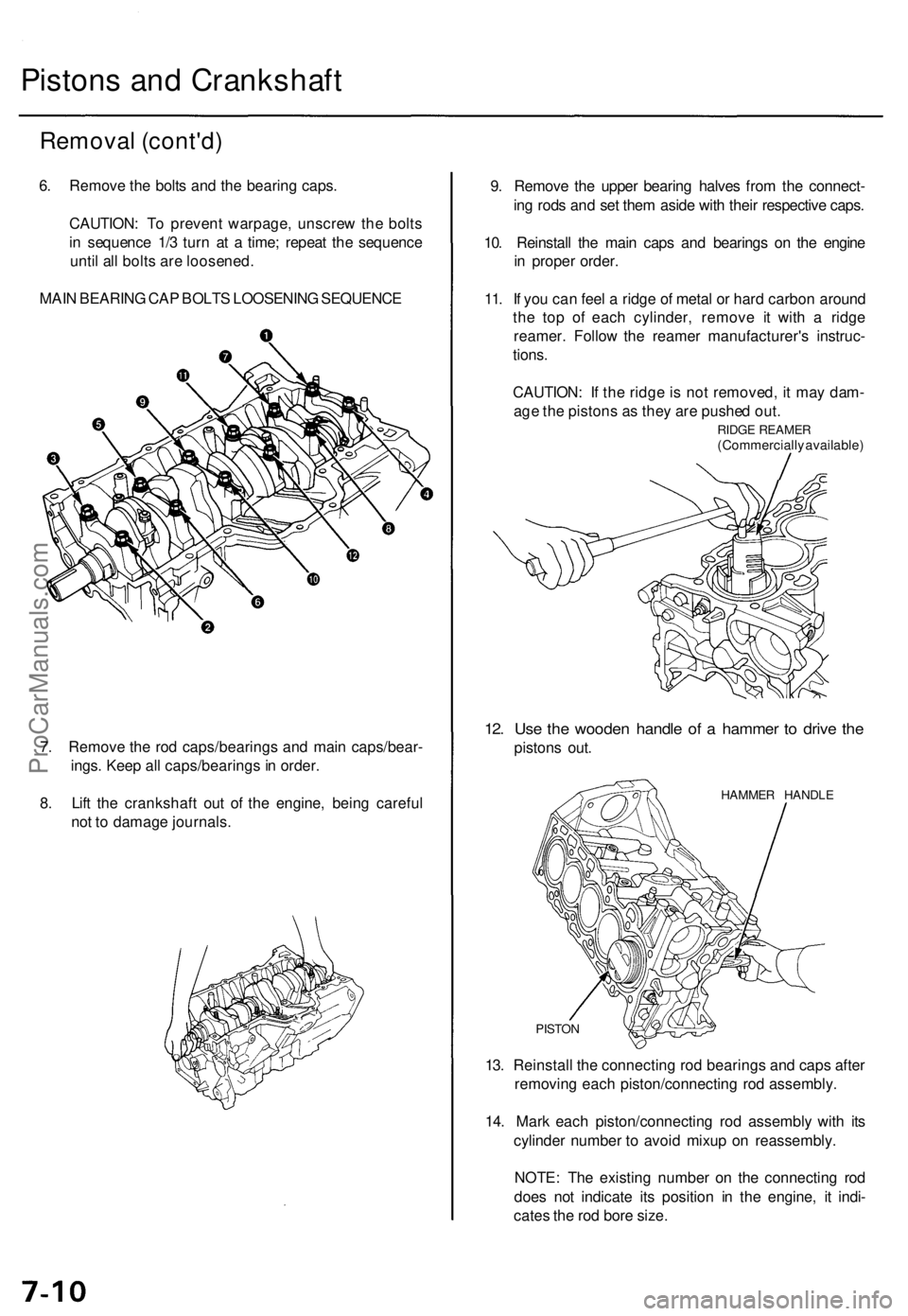
Pistons an d Crankshaf t
Removal (cont'd )
6. Remov e th e bolt s an d th e bearin g caps .
CAUTION : T o preven t warpage , unscre w th e bolt s
i n sequenc e 1/ 3 tur n a t a time ; repea t th e sequenc e
unti l al l bolt s ar e loosened .
MAI N BEARIN G CA P BOLT S LOOSENIN G SEQUENC E
7 . Remov e th e ro d caps/bearing s an d mai n caps/bear -
ings . Kee p al l caps/bearing s in order .
8 . Lif t th e crankshaf t ou t o f th e engine , bein g carefu l
no t t o damag e journals . 9
. Remov e th e uppe r bearin g halve s fro m th e connect -
in g rod s an d se t the m asid e wit h thei r respectiv e caps .
10 . Reinstal l th e mai n cap s an d bearing s o n th e engin e
i n prope r order .
11 . I f yo u ca n fee l a ridg e o f meta l o r har d carbo n aroun d
th e to p o f eac h cylinder , remov e i t wit h a ridg e
reamer . Follo w th e reame r manufacturer' s instruc -
tions .
CAUTION : I f th e ridg e is no t removed , i t ma y dam -
ag e th e piston s a s the y ar e pushe d out .
RIDG E REAME R(Commerciall y available )
12. Us e th e woode n handl e o f a hamme r t o driv e th e
piston s out .
HAMME R HANDL E
PISTON
13. Reinstal l th e connectin g ro d bearing s an d cap s afte r
removin g eac h piston/connectin g ro d assembly .
14 . Mar k eac h piston/connectin g ro d assembl y wit h it s
cylinde r numbe r t o avoi d mixu p o n reassembly .
NOTE : Th e existin g numbe r o n th e connectin g ro d
doe s no t indicat e it s positio n i n th e engine , i t indi -
cate s th e ro d bor e size .
ProCarManuals.com